CROSS REFERENCE TO RELATED APPLICATIONS
The present application claims the benefit of U.S. Provisional Patent Application No. 62/213,863, filed on Sep. 3, 2015. The entire disclosure of the above application is incorporated herein by reference.
FIELD
The present disclosure relates to hydraulically controlled clutch systems and more specifically to devices used to attenuate clutch pedal vibration.
BACKGROUND
The statements in this section merely provide background information related to the present disclosure and may or may not constitute prior art.
Many modern motor vehicle manually shifted transmissions utilize controlled hydraulic fluid to engage or disengage a clutch during transmission gear shifting. A clutch pedal is positioned proximate to a vehicle brake pedal in a driver side compartment of the motor vehicle and may include a rigid rod extending from the clutch pedal through a firewall and into an engine compartment of the motor vehicle. A hydraulic fluid line, also designated as a clutch release line, is routed through the engine compartment from a clutch master cylinder to a clutch slave cylinder.
Vehicle and engine vibrations, particularly those associated with the engine and transmission may transfer via the clutch release line to the clutch pedal. System vibrations in a frequency ranging between approximately 50 Hz to approximately 225 Hz may be “felt” by the vehicle operator during clutch pedal operation. These vibrations are undesirable as they lead to a generally negative interpretation of vehicle ride quality.
Attempts have therefore been made to reduce hydraulic clutch release line vibration that is transferred to the clutch pedal. Such attempts include adding features in the clutch release line to absorb or attenuate hydraulic system vibration, including use of a diaphragm attenuator, or a hydraulic de-coupler. Known diaphragm attenuators have a fluid chamber within which is positioned a flexible metal or resilient material diaphragm which absorbs hydraulic fluid energy and thereby attenuates vibration. Such diaphragm attenuators provide incremental improvement in vibration attenuation over a non-attenuated system, but do not achieve a desirable attenuation (approximately 20 dB attenuation), plus they add component parts that may wear over time. Also known to help attenuate clutch release line and clutch pedal vibration are hydraulic de-couplers. Known hydraulic de-couplers include multiple components including releasable body halves and internal moving parts which displace to attenuate hydraulic vibration. Such de-couplers are more effective in achieving vibration attenuation than known diaphragm attenuators, but are expensive and have moving component parts that also may wear over time.
SUMMARY
An expansion chamber device for clutch pedal vibration attenuation includes a cylindrical body having an inlet line integrally connected to and penetrating through a first end wall of the body. At an opposite end of the body a discharge line is integrally connected to and penetrates a second end wall of the body. A diameter “D” of the expansion chamber device is approximately 3.8 cm and a length “L” of the expansion chamber device ranges between approximately 10.2 cm to 15.2 cm.
According to further aspects, the device has no internal moving parts.
According to further aspects, the device provides at least 20 dB of vibration attenuation in a hydraulic clutch line and a hydraulic clutch pedal system, compared to a hydraulic clutch line and a hydraulic clutch pedal system having no vibration attenuation.
According to further aspects, the inlet line and the discharge line penetrate the respective first or second end wall centrally aligned with the wall and co-axially aligned with a longitudinal axis of the body.
According to further aspects, an inner chamber of the cylindrical body is approximately 6 times larger than a diameter of the inlet line and the discharge line.
According to further aspects, wherein the second end wall of the expansion chamber device is a vertically oriented, outwardly tapered wall.
According to further aspects, wherein the second end wall of the expansion chamber device is a substantially flat wall.
According to further aspects, wherein the discharge line is positioned at an upper end or the top center apex of the second end wall.
According to further aspects, the inlet line includes an extending portion which discharges hydraulic fluid away from the first end wall and proximate to a center of an inner chamber.
According to further aspects, the discharge line includes an extending portion which receives hydraulic fluid away from the second end wall and proximate to the center of the inner chamber.
Further features, advantages, and areas of applicability will become apparent from the description provided herein. It should be understood that the description and specific examples are intended for purposes of illustration only and are not intended to limit the scope of the present disclosure.
DRAWINGS
The drawings described herein are for illustration purposes only and are not intended to limit the scope of the present disclosure in any way. The components in the figures are not necessarily to scale, emphasis instead being placed upon illustrating the principles of the present disclosure. Moreover, in the figures, like reference numerals designate corresponding parts throughout the views. In the drawings:
FIG. 1 is a front perspective view of a motor vehicle engine compartment having an expansion chamber device for hydraulic vibration attenuation of the present disclosure;
FIG. 2 is a diagrammatic front elevational view of the expansion chamber device in accordance with the principles of the present disclosure;
FIG. 3 is a diagrammatic front elevational view of an expansion chamber device in accordance with another aspect of the present disclosure;
FIG. 4 is a diagrammatic front elevational view of an expansion chamber device in accordance with another aspect of the present disclosure;
FIG. 5 is a diagrammatic front elevational view of an expansion chamber device in accordance with another aspect of the present disclosure;
FIG. 6 is a front elevational view of the expansion chamber device of FIG. 1, further including venting components; and
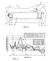
FIG. 7 is a graph comparing hydraulic acceleration amplitudes for an expansion chamber device in accordance with aspects of the present disclosure compared to a hydraulic system having no vibration attenuation and two hydraulic systems having expansion chamber devices with modified dimensions.
DETAILED DESCRIPTION
The following description is merely exemplary in nature and is not intended to limit the present disclosure, application, or uses.
With reference to FIG. 1, a motor vehicle engine compartment generally indicated by reference number 10 includes an exemplary expansion chamber device 12 used for clutch pedal vibration attenuation. The expansion chamber device 12 is installed for example in a clutch release line 14 containing a hydraulic fluid (brake fluid), and leads into a clutch slave cylinder line 16, and ultimately to a clutch slave cylinder (not shown). The clutch release line 14 may be a hard pipe or tube, or a flexible hose, and the clutch slave cylinder line 16 is commonly a flexible hose. The expansion chamber device 12 is positioned in the engine compartment 10 forward of a firewall 18, and preferably positioned proximate to a clutch master cylinder 20. This location of the expansion chamber device 12 is not limiting, as the expansion chamber device 12 can be located at any location within the engine compartment 10. The expansion chamber device 12 is itself directly mounted to structure or another component in the engine compartment 10 to limit deflection of the expansion chamber device 12 that may occur due to the mass of the expansion chamber device 12 being substantively greater than a significantly smaller mass and flexibility of the connecting clutch release line 14 or the clutch slave cylinder line 16. The expansion chamber device 12 actively reduces vehicle and engine vibrations in a path including a clutch pedal over a frequency range between approximately 50 Hz to approximately 225 Hz.
Referring to FIG. 2 and again to FIG. 1, according to several aspects, the expansion chamber device 12 includes a cylindrical body 22 having an inlet port or line 24 integrally connected to and penetrating through a first end wall 26 of the body 22. At an opposite end of the body 22 a discharge port or line 28 is integrally connected to and penetrates a second end wall 30 of the body 22. The positions where the inlet line 24 and the discharge line 28 penetrate the respective first or second end wall 26, 28 are shown centrally aligned with the walls and co-axially aligned with a central longitudinal axis “X” of the body 22, however this location is not limiting. According to several aspects, a diameter “D” of the expansion chamber device 12 is approximately 3.8 cm (1.5 in) and a length “L” of the expansion chamber device 12 ranges between approximately 10.2 cm to 15.2 cm (4.0 to 6.0 in), with the preferred length being the greatest length (closest to 15.2 cm) that can be accommodated in the space limitations of the engine compartment 10 of the motor vehicle. According to several aspects, the diameter “D” of the expansion chamber device 12 can vary between approximately 2.5 cm (1.0in) to approximately 3.8 cm (1.5 in). A diameter “d” of both the inlet line 24 and the discharge line 28 is typically approximately 0.6 cm (0.25 in), therefore the diameter “D” of an inner chamber 31 of the cylindrical body 22 is substantially larger (approximately 6 times larger) than the diameter of the inlet line 24 and the discharge line 28.
Referring to FIG. 3 and again to FIGS. 1 and 2, according to further aspects, an expansion chamber device 32 is modified from the expansion chamber device 12. Expansion chamber device 32 includes a cylindrical body 34 but replaces the flat second end wall 30 of the expansion chamber device 12 with a vertically oriented, outwardly tapered wall 36. By orienting the expansion chamber device 32 with the tapered wall 36 facing vertically upward, a discharge line 38 and an inlet line 40 penetrating a first end wall 42 are also vertically oriented, such that hydraulic fluid in the expansion chamber device 32 will self-vent.
Referring to FIG. 2 and again to FIG. 1, according to several aspects, the expansion chamber device 12 includes a cylindrical body 22 having an inlet port or line 24 integrally connected to and penetrating through a first end wall 26 of the body 22. At an opposite end of the body 22 a discharge port or line 28 is integrally connected to and penetrates a second end wall 30 of the body 22. The positions where the inlet line 24 and the discharge line 28 penetrate the respective first or second end wall 26, 28 are shown centrally aligned with the walls and co-axially aligned with a central longitudinal axis “X” of the body 22, however this location is not limiting. According to several aspects, a diameter “D” of the expansion chamber device 12 is approximately 3.8 cm (1.5 in) and a length “L” of the expansion chamber device 12 ranges between approximately 10.2 cm to 15.2 cm (4.0 to 6.0in), with the preferred length being the greatest length (closest to 15.2 cm) that can be accommodated in the space limitations of the engine compartment 10 of the motor vehicle. According to several aspects, the diameter “D” of the expansion chamber device 12 can vary between approximately 2.5 cm (1.0in) to approximately 3.8 cm (1.5 in). A diameter “d” of both the inlet line 24 and the discharge line 28 is typically approximately 0.6 cm (0.25in), therefore the diameter “D” of an inner chamber 31 of the cylindrical body 22 is substantially larger (approximately 6 times larger) than the diameter of the inlet line 24 and the discharge line 28.
Referring to FIG. 3 and again to FIGS. 1 and 2, according to further aspects, an expansion chamber device 32 is modified from the expansion chamber device 12. Expansion chamber device 32 includes a cylindrical body 34 but replaces the flat second end wall 30 of the expansion chamber device 12 with a vertically oriented, outwardly tapered wall 36. By orienting the expansion chamber device 32 with the tapered wall 36 facing vertically upward, a discharge line 38 and an inlet line 40 penetrating a first end wall 42 are also vertically oriented, such that hydraulic fluid in the expansion chamber device 32 will self-vent.
Referring now to FIG. 4 and again to FIGS. 1 through 3, according to several aspects an expansion chamber device 44 is modified from the expansion chamber device 12. Expansion chamber device 44 includes a horizontal inlet line 46 which can be centrally positioned in a first end wall 48 of a cylindrical body 50. The expansion chamber device 44 repositions a discharge line 52 compared to the discharge line 28 from a center or coaxial to the longitudinal axis of a second end wall 54 to an upper end or the top center apex of the second end wall 54. By orienting the expansion chamber device 44 with the discharge line 52 facing upward, hydraulic fluid in an inner chamber 56 of the cylindrical body 50 will self-vent.
Referring to FIG. 5 and again to FIGS. 1-4, according to further aspects, an expansion chamber device 58 is modified to include a cylindrical body 60 having an inlet port or line 62 integrally connected to and penetrating through a first end wall 64 of the body 60. The inlet line 62 includes an extending portion 66 which discharges hydraulic fluid away from the first end wall 64 and therefore proximate to a center of an inner chamber 68. At an opposite end of the body 60 a discharge port or line 70 is integrally connected to and penetrates a second end wall 72 of the body 60. The discharge line 70 similarly includes an extending portion 74 which receives hydraulic fluid away from the second end wall 72 and proximate to the center of the inner chamber 68. The positions where the inlet line 62 and the discharge line 70 penetrate the respective first or second end wall 64, 72 are shown centrally aligned with the walls or co-axial with a longitudinal axis of the body, however these positions can vary to change the self-venting characteristics of the expansion chamber device 58.
It is anticipated that the positions of the extending portions 66, 74 away from the penetration location at the respective walls and close to the center of the inner chamber 68 provides additional vibration attenuation. For example, as the hydraulic fluid enters the inner chamber 68 from extending portion 66, vibrations from the vehicle drive train propagate through the hydraulic fluid as waves. Wave reflection is generated in substantially all directions within the inner chamber 68, thereby decreasing reflected vibration wave amplitude and improving vibration attenuation. Similar to the configuration discussed in reference to FIG. 4, by orienting the expansion chamber device 58 with the discharge line 70 facing upward (not shown), hydraulic fluid in the inner chamber 68 of the cylindrical body 60 will self-vent.
Referring to FIG. 6 and again to FIG. 2, the venting properties of the expansion chamber device 12 can be further improved by the addition of an inlet fitting 76 directly connected to the first end wall 26 of the body 22, which provides a hydraulic line connector 78, and a bleed or vent port 80. Similarly an outlet fitting 82 directly connected to the second end wall 30 of the body 22 can provide a hydraulic line connector 84, and a bleed or vent port 86.
Referring to FIG. 7, a graph provides exemplary test data comparing acceleration amplitude versus frequency for measured systems having no hydraulic vibration attenuation (curve 90); a 2.5 cm (1.0 in) diameter ×15.2cm (6.0 in) long expansion chamber device (curve 92); a 5.0 cm (2.0 in) diameter ×10.2 cm (4.0 in) long expansion chamber device (curve 94); and the 3.8 cm (1.5 in) diameter ×15.2 cm (6.0 in) long expansion chamber device 12 (curve 96). As evident by curve 96 at least 20 dB attenuation is achieved by the expansion chamber device 12 over a frequency ranging between approximately 50.0 Hz to approximately 225.0 Hz.
Vibration attenuators or expansion chamber devices of the present disclosure have no internal moving parts, do not include any internal vanes or flow restrictors, and do not include any internal flow deflectors. Material used for the expansion chamber devices of the present disclosure can include polymeric materials, composite materials, or metal. The expansion chamber devices can be positioned at any desired location along the clutch release line connected to the clutch master cylinder, or in the line leading to the clutch slave cylinder.
The description of the present disclosure is merely exemplary in nature and variations that do not depart from the gist of the present disclosure are intended to be within the scope of the present disclosure. Such variations are not to be regarded as a departure from the spirit and scope of the present disclosure.