US9829273B2 - Gun grip with finger placement and holstering features - Google Patents

Gun grip with finger placement and holstering features Download PDF

Info

Publication number
US9829273B2
US9829273B2 US15/183,794 US201615183794A US9829273B2 US 9829273 B2 US9829273 B2 US 9829273B2 US 201615183794 A US201615183794 A US 201615183794A US 9829273 B2 US9829273 B2 US 9829273B2
Authority
US
United States
Prior art keywords
grip
firearm
trigger
finger
user
Prior art date
Legal status (The legal status is an assumption and is not a legal conclusion. Google has not performed a legal analysis and makes no representation as to the accuracy of the status listed.)
Expired - Fee Related
Application number
US15/183,794
Other versions
US20170059272A1 (en
Inventor
Jason Lane Cazes
Current Assignee (The listed assignees may be inaccurate. Google has not performed a legal analysis and makes no representation or warranty as to the accuracy of the list.)
Individual
Original Assignee
Individual
Priority date (The priority date is an assumption and is not a legal conclusion. Google has not performed a legal analysis and makes no representation as to the accuracy of the date listed.)
Filing date
Publication date
Application filed by Individual filed Critical Individual
Priority to US15/183,794 priority Critical patent/US9829273B2/en
Publication of US20170059272A1 publication Critical patent/US20170059272A1/en
Application granted granted Critical
Publication of US9829273B2 publication Critical patent/US9829273B2/en
Expired - Fee Related legal-status Critical Current
Anticipated expiration legal-status Critical

Links

Images

Classifications

    • FMECHANICAL ENGINEERING; LIGHTING; HEATING; WEAPONS; BLASTING
    • F41WEAPONS
    • F41CSMALLARMS, e.g. PISTOLS, RIFLES; ACCESSORIES THEREFOR
    • F41C23/00Butts; Butt plates; Stocks
    • F41C23/10Stocks or grips for pistols, e.g. revolvers
    • FMECHANICAL ENGINEERING; LIGHTING; HEATING; WEAPONS; BLASTING
    • F41WEAPONS
    • F41CSMALLARMS, e.g. PISTOLS, RIFLES; ACCESSORIES THEREFOR
    • F41C33/00Means for wearing or carrying smallarms
    • F41C33/006Clips, hooks or the like, for carrying the weight of smallarms
    • F41C33/008Clips, hooks or the like, for carrying the weight of smallarms for handguns, i.e. pistols or revolvers
    • FMECHANICAL ENGINEERING; LIGHTING; HEATING; WEAPONS; BLASTING
    • F41WEAPONS
    • F41CSMALLARMS, e.g. PISTOLS, RIFLES; ACCESSORIES THEREFOR
    • F41C33/00Means for wearing or carrying smallarms
    • F41C33/02Holsters, i.e. cases for pistols having means for being carried or worn, e.g. at the belt or under the arm
    • F41C33/0236Half-holsters covering by encircling only a part of the small arm, e.g. ghost-holsters
    • FMECHANICAL ENGINEERING; LIGHTING; HEATING; WEAPONS; BLASTING
    • F41WEAPONS
    • F41CSMALLARMS, e.g. PISTOLS, RIFLES; ACCESSORIES THEREFOR
    • F41C33/00Means for wearing or carrying smallarms
    • F41C33/02Holsters, i.e. cases for pistols having means for being carried or worn, e.g. at the belt or under the arm
    • F41C33/04Special attachments therefor
    • F41C33/041Special attachments therefor for connecting a holster to a belt, webbing or other object

Definitions

  • the present invention is in the technical field of firearms. More particularly, the present invention is in the technical field of handgun grips. Most particularly, the present invention is in the technical field of handgun grips with finger placement features and holstering features.
  • firearms For centuries, humans have used firearms for hunting, sport and self-defense.
  • firearms may be broken down into three broad types: shotguns, rifles and handguns.
  • Shotguns and rifles in general, feature elongated designs, whereas handguns are typically constructed in such a manner as to allow the user to easily hold and fire the firearm with one hand.
  • Holsters may be worn in a variety of places on the user's body and may either conceal a handgun or allow for open carry. Almost all holsters on the market are designed to envelop the handgun within a “sheath-like” material. When the user wishes to remove the handgun from a holster, he slides the handgun out from the sheath, reversing this process when he wishes to holster his handgun.
  • holsters contribute a fair amount of bulk to the outline of a handgun, which is often undesirable.
  • many holsters require attachment mechanisms to affix the holster to the user's clothing, some requiring partial undress to remove a holster from the user's person.
  • a product that allows discrete carry of a handgun, while improving accuracy is thus highly desirable. It is the goal of the present invention to remedy problems found with current products in the prior art.
  • Prior art teaches clips that allow a handgun owner to clip his handgun onto his clothing.
  • Prior art also teaches accuracy-improving devices designed to place a user's index finger in the optimal position on a trigger. The inventor believes the present invention is a new and useful invention not disclosed by the prior art and believes patent protection is warranted.
  • a grip assembly for handguns comprises a palm rest that is attached to a handgun by replacing the factory palm rest(s), by utilizing factory attachment points or by a wraparound design.
  • the top of the palm rest features a finger rest that runs forward parallel to, and below, the slide or barrel of the handgun, said finger rest ending slightly further from the end of the barrel as the trigger of the handgun.
  • Said finger rest features a gap between the internal surface of the finger rest and the frame of the handgun, providing proper placement of the user's finger on the trigger when in use and forming a clip for the user to attach the handgun about his person when the handgun is not in use.
  • the entire grip assembly may be manufactured from materials commonly used in the industry including, but not limited to, natural and synthetic rubbers, wood, nylon, composite plastics and metals. Furthermore, impregnation of the grip assembly's material with abrading particles or texturing of the surface of the grip assembly may provide additional tack.
  • FIG. 1 is a side view of one embodiment of the present invention
  • FIG. 2 is a side view of the same embodiment, shown affixed to one popular handgun design
  • FIG. 3 is a top view of the same embodiment, showing protrusion from the handgun's frame and demonstrating the finger rest and clip features of the present invention
  • FIG. 4 is a front view of the same embodiment
  • FIG. 5 is a side view of an alternative embodiment of the present invention.
  • FIG. 6 is a side view of the same embodiment of FIG. 5 , shown affixed to an alternative popular handgun design;
  • FIG. 7 is a side view of a substantially-similar embodiment as FIG. 5 , this embodiment including a beavertail feature;
  • FIG. 8 is a top view of the same embodiment as shown in FIG. 5 , showing protrusion from the handgun's frame and demonstrating the finger rest and clip features of the present invention
  • FIG. 9 is an internal view of the same embodiment as shown in FIG. 5 , showing placement of attachment holes and the placement of an attachment tab;
  • FIG. 10 is a front view of the same embodiment of the present invention as shown in FIG. 5 , shown attached to a handgun frame;
  • FIG. 11 is a side view of another alternative embodiment of the present invention.
  • FIG. 12 is a top view of the same embodiment of the present invention shown in FIG. 11 , showing protrusion from the handgun's frame and demonstrating the finger rest and clip features of the present invention;
  • FIG. 13 is a bottom view of the same embodiment of the present invention shown in FIG. 11 ;
  • FIG. 14 is an internal view of the same embodiment of the present invention shown in FIG. 11 , showing placement of attachment holes and attachment tabs;
  • FIG. 15 is a side view of a the embodiment shown in FIG. 11 , installed on another handgun design;
  • FIG. 16 is a side view of a substantially-similar embodiment as FIG. 15 , this embodiment including a beavertail feature;
  • FIG. 17 is a top view of the same embodiment as shown in FIG. 11 , showing protrusion from the handgun's frame and demonstrating the finger rest and clip features of the present invention
  • FIG. 18 is a front view of the same embodiment as shown in FIG. 11 , showing protrusion from the handgun's frame and demonstrating the finger rest and clip features of the present invention
  • FIG. 19 is a side view of another alternative embodiment of the present invention.
  • FIG. 20 is a side view of the same embodiment of FIG. 19 , shown affixed to an alternative handgun design;
  • FIG. 21 is a top view of the same embodiment of the present invention shown in FIG. 19 , showing protrusion from the handgun's frame and demonstrating the finger rest and clip features of the present invention
  • FIG. 22 is a front view of the same embodiment of the present invention shown in FIG. 19 , affixed to a handgun frame;
  • FIG. 23 is a side view of another alternative embodiment of the present invention.
  • FIG. 24 is a top view of the same embodiment of the present invention shown in FIG. 23 ;
  • FIG. 25 is a side view of another alternative embodiment of the present invention.
  • FIG. 26 is side view of the same embodiment of FIG. 25 , shown affixed to the pistol grip portion of one popular type of rifle and demonstrating applicability of the present invention to long guns;
  • FIG. 27 is a side view of another alternative embodiment of the present invention.
  • FIG. 28 is a top view of the same embodiment of the present invention shown in FIG. 27 ;
  • FIG. 29 is a top view of the same embodiment of the present invention shown in FIG. 28 and attached to one popular model of handgun.
  • FIG. 1 there is shown the present invention designed for one popular model of handgun.
  • a palm rest 100 is featured running vertically and at a slight forward angle for the user to grasp.
  • a finger rest 102 continues forward toward the end of the barrel of the handgun.
  • FIG. 1 also demonstrates attachment points 104 for the user to affix the present invention to the frame of a handgun.
  • FIG. 2 is a side view of the present invention attached to one popular model of handgun. The furthest-forward portion of the finger rest 102 is shown ending slightly before the trigger on this model of handgun.
  • FIG. 3 shows the present invention as attached to the same model of handgun as FIGS. 1-2 .
  • the inner surface of the finger rest 102 protrudes slightly from the frame of the handgun.
  • the finger rest 102 helps position the user's finger so that the proper region of the user's finger is placed on the trigger when he is ready to fire.
  • FIG. 3 demonstrates the clip function of the present invention.
  • FIG. 4 is a front view of the present invention, looking down the barrel of the gun.
  • FIG. 4 best-demonstrates the relative location of the finger rest 102 to the palm rest 100 .
  • FIGS. 5-6, 8 and 10 there is shown an alternative embodiment of the present invention, designed for attachment to another popular model of handgun.
  • a palm rest 200 As with FIGS. 1-4 , there is shown a palm rest 200 , finger rest 202 and attachment points 204 , all of which serve the same function as the prior embodiment of the present invention.
  • FIG. 7 demonstrates one slight variation to this particular embodiment of the present invention.
  • Some handgun models have the tendency to knick the user's thumb knuckle when the slide recoils backwards as the gun is fired.
  • This variation of the present invention features a beavertail 206 to protect the user's knuckle.
  • FIG. 9 is a front-to-rear view of the internal components of this embodiment of the present invention.
  • FIG. 9 shows the locations of the attachment points 204 , inner portion of the palm rest 200 and the finger rest 202 .
  • the model of handgun for which this embodiment was designed features a hollow opening at the base of the grip.
  • This embodiment of the present invention may feature an attachment tab 208 , designed to slide into the hollow opening, providing an additional attachment point.
  • FIG. 11 there is shown another alternative embodiment to the present invention. Shown in FIG. 11 are the relative locations of the palm rest 300 and finger rest 302 . Noticeably absent are attachment points as featured in prior Figs. It is common for handguns to not feature holes for grip attachment, instead using attachment tabs internal to the grip components to secure the grips to the handgun frame.
  • the alternative embodiment of the present invention as shown in FIGS. 11-18 demonstrate such attachment mechanisms.
  • FIG. 12 shows a top view of the alternative embodiment of the present invention, apart from a handgun.
  • An attachment tab 308 is shown.
  • the precise location of the attachment tab 308 on this embodiment is variable, but will correspond to the location of attachment points within the frame of handguns for which this embodiment is designed.
  • FIG. 13 is a bottom view of the same embodiment of the present invention.
  • the model of handgun for which this embodiment is intended features a hole at the base of the grip.
  • This embodiment features an attachment point 304 for the user to place the pin from the factory grip.
  • FIG. 14 is a front-to-rear view of internal components of the current embodiment of the present invention showing its particular attachment features. There are shown attachment tabs 308 at the top and sides of the palm rest 300 . Furthermore, there are shown attachment points 304 at the bottom of the palm grip 300 for placement of the factory grip pin.
  • FIG. 15 shows placement of the current embodiment upon the frame of the handgun for which it was designed.
  • FIG. 16 shows a slight variation to the current embodiment that features a beavertail 306 with substantially similar form and function as the one in FIG. 7 .
  • FIGS. 17-18 show top and front views of the current embodiment of the present invention upon the frame of a handgun, demonstrating the relative location of the present invention to the handgun's body.
  • FIG. 19 is a view of another alternative embodiment of the present invention, as designed for handguns commonly referred to as revolvers. There are shown the palm rest 400 , finger rest 402 and an attachment point 404 , all of which serve the same function as in the previously discussed embodiments of the present invention.
  • FIGS. 20-22 shows placement of the current embodiment on a revolver and demonstrate the relative positioning of the components to the handgun overall.
  • FIGS. 23-24 are views of an alternative embodiment of the present invention, this embodiment designed to slide onto the grip of handguns with a wraparound design.
  • the palm rest 500 wraps about the factory grip of the handgun.
  • the palm rest 500 is constructed of materials of sufficient stretch to fit around the grip of the handgun and hold this embodiment in place via compression of the materials of the palm rest 500 around the grip of the handgun.
  • the current embodiment features a finger rest 502 , which serves the same function in this embodiment as in the others.
  • FIGS. 25-26 are views of an alternative embodiment of the present invention, demonstrating how it may also be used on all guns featuring pistol-style grips. As with the other embodiments, there is shown a palm rest 600 and a finger rest 602 . This embodiment may be slid over the grip of a long gun, such as with the embodiment of the invention shown in FIGS. 23-24 , or may completely replace the factory grip.
  • FIGS. 27-29 demonstrate a final embodiment of the present invention.
  • This particular embodiment features a hinge 710 as well as a spring 712 .
  • the hinge 710 and spring 712 are only shown placed on the embodiment of the present invention shown in FIGS. 11-18 .
  • the inventor would like to explicitly point out all embodiments of the present invention may possibly feature a hinge 710 and spring 712 .
  • FIG. 27 shows a hinge 710 and its placement relative to the palm rest 700 and finger rest 702 portion of this embodiment of the present invention.
  • the hinge 710 allows the finger rest 702 to swing outward when pulled away from the frame of a gun.
  • FIG. 28 shows the location of a spring 712 internal to the hinge 710 discussed in the preceding paragraph.
  • tension is placed upon the spring 712 .
  • This tension may provide for a more secure attachment of the gun to the user's person or clothing when the holstering feature of the present invention is used.
  • the spring 712 may be a coil spring, a leaf spring, or a spring of any other type as suitable to the spirit and function of the present invention.
  • FIG. 29 shows how the interaction between the hinge 710 and spring 712 would allow the finger rest 702 to be adjusted further from the frame of the gun, when the holstering feature is desired.
  • the user affixes the palm rest 100 200 300 400 600 700 about the frame of the handgun or grip, either by replacing the factory grip using factory-attachment points (where available) or by sliding the palm rest 500 about the frame (in the wraparound embodiment).
  • the palm rest 100 200 300 400 500 600 700 is affixed to the frame of the handgun or gun, the design of all embodiments leads to proper placement of the finger rest 102 202 302 402 502 602 702 along the frame of the handgun or gun.
  • Firing a handgun featuring the present invention is functionally identical to firing one without the present invention. All safety features remain accessible. Overall safety is improved by accuracy improvements through better placement of the user's index finger upon the trigger. A handgun fired more accurately is a safer handgun.
  • the holstering feature of the present invention is equally simple. By nature of its design, the gap between the internal surface of the finger rest 102 202 302 402 502 602 702 and the slide or barrel of the handgun allows the finger rest 102 202 302 402 502 602 702 to serve the additional function of a clip.
  • This clipping feature allows the user to discretely clip the handgun about his body when not in use.
  • the preferred use of the clip feature is to allow the user to clip the handgun to his clothing or belt, though the inventor does not intend to limit the application to only clip to clothing.
  • Embodiments of the present invention utilizing a hinge 710 and a spring 712 operate in the same manner, with the additional security of a spring-tensioned attachment mechanism.
  • the present invention is a firearm grip with finger placement and holstering features.

Landscapes

  • Engineering & Computer Science (AREA)
  • General Engineering & Computer Science (AREA)
  • Purses, Travelling Bags, Baskets, Or Suitcases (AREA)
  • Gloves (AREA)

Abstract

A device designed to replace or supplement the factory grip of a firearm, said device improving accuracy by allowing better placement of the user's trigger finger upon the trigger of the firearm, said device also providing an attachment point for carry of the firearm about the user's person when the firearm is not in use.

Description

CROSS-REFERENCE TO RELATED APPLICATIONS
This application claims priority of Provisional Patent Application 62/180,572, filing date Jun. 16, 2015.
STATEMENT REGARDING FEDERALLY SPONSORED RESEARCH OR DEVELOPMENT
Not Applicable
REFERENCE TO SEQUENCE LISTING, A TABLE, OR A COMPUTER PROGRAM LISTING COMPACT DISK APPENDIX
Not Applicable
BACKGROUND OF THE INVENTION
The present invention is in the technical field of firearms. More particularly, the present invention is in the technical field of handgun grips. Most particularly, the present invention is in the technical field of handgun grips with finger placement features and holstering features.
For centuries, humans have used firearms for hunting, sport and self-defense. For the purposes of this application, firearms may be broken down into three broad types: shotguns, rifles and handguns. Shotguns and rifles, in general, feature elongated designs, whereas handguns are typically constructed in such a manner as to allow the user to easily hold and fire the firearm with one hand.
It is desirable for firearms users to fire their weapons accurately and safely. For handgun users, the ability to effectively conceal a handgun, while still allowing quick access, is also a common desire. These factors have given rise to a multitude of products designed for the shooting community, many of which serve intended purposes of improving accuracy and allowing concealed carry when a user does not wish to display the fact he is carrying a handgun.
For ease in understanding the present invention, a brief overview of proper shooting technique is warranted. It is generally accepted in the shooting community that a handgun shooter fires a handgun most accurately when the fleshy portion of a shooter's index finger (the portion equidistant between the terminus of the finger and the first knuckle) is placed on the trigger. Often times, the configuration of standard handgun grips and the length of the shooter's index finger, taken in tandem, cause the shooter to improperly place his index finger on the trigger of a handgun. As a result of this placement, the shooter often tends to “pull” or “push” the handgun slightly to one side when firing, reducing accuracy. Proper finger placement on the trigger allows the user to smoothly pull the trigger backwards, leading to more accurate shot placement.
A brief discussion of standard handgun holsters is also warranted. Holsters may be worn in a variety of places on the user's body and may either conceal a handgun or allow for open carry. Almost all holsters on the market are designed to envelop the handgun within a “sheath-like” material. When the user wishes to remove the handgun from a holster, he slides the handgun out from the sheath, reversing this process when he wishes to holster his handgun.
The primary problem with holsters on the market is holsters contribute a fair amount of bulk to the outline of a handgun, which is often undesirable. In addition, many holsters require attachment mechanisms to affix the holster to the user's clothing, some requiring partial undress to remove a holster from the user's person. A product that allows discrete carry of a handgun, while improving accuracy is thus highly desirable. It is the goal of the present invention to remedy problems found with current products in the prior art.
The inventor has performed a prior art search. Prior art teaches clips that allow a handgun owner to clip his handgun onto his clothing. Prior art also teaches accuracy-improving devices designed to place a user's index finger in the optimal position on a trigger. The inventor believes the present invention is a new and useful invention not disclosed by the prior art and believes patent protection is warranted.
SUMMARY OF THE INVENTION
A grip assembly for handguns comprises a palm rest that is attached to a handgun by replacing the factory palm rest(s), by utilizing factory attachment points or by a wraparound design. The top of the palm rest features a finger rest that runs forward parallel to, and below, the slide or barrel of the handgun, said finger rest ending slightly further from the end of the barrel as the trigger of the handgun. Said finger rest features a gap between the internal surface of the finger rest and the frame of the handgun, providing proper placement of the user's finger on the trigger when in use and forming a clip for the user to attach the handgun about his person when the handgun is not in use. The entire grip assembly may be manufactured from materials commonly used in the industry including, but not limited to, natural and synthetic rubbers, wood, nylon, composite plastics and metals. Furthermore, impregnation of the grip assembly's material with abrading particles or texturing of the surface of the grip assembly may provide additional tack.
The specific aspects, features and advantages of the present invention will become apparent from the following detailed description of the varying embodiments of the present invention.
BRIEF DESCRIPTION OF THE DRAWINGS
FIG. 1 is a side view of one embodiment of the present invention;
FIG. 2 is a side view of the same embodiment, shown affixed to one popular handgun design;
FIG. 3 is a top view of the same embodiment, showing protrusion from the handgun's frame and demonstrating the finger rest and clip features of the present invention;
FIG. 4 is a front view of the same embodiment;
FIG. 5 is a side view of an alternative embodiment of the present invention;
FIG. 6 is a side view of the same embodiment of FIG. 5, shown affixed to an alternative popular handgun design;
FIG. 7 is a side view of a substantially-similar embodiment as FIG. 5, this embodiment including a beavertail feature;
FIG. 8 is a top view of the same embodiment as shown in FIG. 5, showing protrusion from the handgun's frame and demonstrating the finger rest and clip features of the present invention;
FIG. 9 is an internal view of the same embodiment as shown in FIG. 5, showing placement of attachment holes and the placement of an attachment tab;
FIG. 10 is a front view of the same embodiment of the present invention as shown in FIG. 5, shown attached to a handgun frame;
FIG. 11 is a side view of another alternative embodiment of the present invention;
FIG. 12 is a top view of the same embodiment of the present invention shown in FIG. 11, showing protrusion from the handgun's frame and demonstrating the finger rest and clip features of the present invention;
FIG. 13 is a bottom view of the same embodiment of the present invention shown in FIG. 11;
FIG. 14 is an internal view of the same embodiment of the present invention shown in FIG. 11, showing placement of attachment holes and attachment tabs;
FIG. 15 is a side view of a the embodiment shown in FIG. 11, installed on another handgun design;
FIG. 16 is a side view of a substantially-similar embodiment as FIG. 15, this embodiment including a beavertail feature;
FIG. 17 is a top view of the same embodiment as shown in FIG. 11, showing protrusion from the handgun's frame and demonstrating the finger rest and clip features of the present invention;
FIG. 18 is a front view of the same embodiment as shown in FIG. 11, showing protrusion from the handgun's frame and demonstrating the finger rest and clip features of the present invention;
FIG. 19 is a side view of another alternative embodiment of the present invention;
FIG. 20 is a side view of the same embodiment of FIG. 19, shown affixed to an alternative handgun design;
FIG. 21 is a top view of the same embodiment of the present invention shown in FIG. 19, showing protrusion from the handgun's frame and demonstrating the finger rest and clip features of the present invention
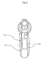
FIG. 22 is a front view of the same embodiment of the present invention shown in FIG. 19, affixed to a handgun frame;
FIG. 23 is a side view of another alternative embodiment of the present invention;
FIG. 24 is a top view of the same embodiment of the present invention shown in FIG. 23;
FIG. 25 is a side view of another alternative embodiment of the present invention;
FIG. 26 is side view of the same embodiment of FIG. 25, shown affixed to the pistol grip portion of one popular type of rifle and demonstrating applicability of the present invention to long guns;
FIG. 27 is a side view of another alternative embodiment of the present invention;
FIG. 28 is a top view of the same embodiment of the present invention shown in FIG. 27;
FIG. 29 is a top view of the same embodiment of the present invention shown in FIG. 28 and attached to one popular model of handgun.
DETAILED DESCRIPTION OF THE INVENTION
The spirit and scope of the present invention allow for construction from a variety of materials and methods. It is anticipated wood, molded plastics, nylons, rubbers, and composites would allow the most cost-effective and lightweight construction, though the inventor does not intend to limit the construction of the present invention to one specific type of material or one specific type of construction.
All Figs. show right-handed versions of the present invention. The inventor does not intend to limit the present invention to only right-handed embodiments. Those skilled in the art will realize the present application also discloses left-handed embodiments by placement of the finger rest portion of the present invention on the left side of the handgun frame.
Furthermore, those skilled in the art will realize that due to the variety of handgun shapes and sizes, it is not feasible to submit figures and detailed descriptions of embodiments for every handgun design on the market. The figures and detailed descriptions of various embodiments are intended not to limit the scope of the application, but to provide as wide a range of disclosure of the present invention as is reasonable.
Referring now to the view of the present invention as shown in FIG. 1, there is shown the present invention designed for one popular model of handgun. A palm rest 100 is featured running vertically and at a slight forward angle for the user to grasp. At the top of the palm rest 100, a finger rest 102 continues forward toward the end of the barrel of the handgun. FIG. 1 also demonstrates attachment points 104 for the user to affix the present invention to the frame of a handgun.
FIG. 2 is a side view of the present invention attached to one popular model of handgun. The furthest-forward portion of the finger rest 102 is shown ending slightly before the trigger on this model of handgun.
FIG. 3 shows the present invention as attached to the same model of handgun as FIGS. 1-2. The inner surface of the finger rest 102 protrudes slightly from the frame of the handgun. The finger rest 102 helps position the user's finger so that the proper region of the user's finger is placed on the trigger when he is ready to fire. In addition, FIG. 3 demonstrates the clip function of the present invention. There is a slight gap between the internal portion of the finger rest 102 and the frame of the handgun. The slight gap allows for an additional clip feature served by utilizing the finger rest 102 as a clip when the user wishes to clip the handgun about his person when not in use.
FIG. 4 is a front view of the present invention, looking down the barrel of the gun. FIG. 4 best-demonstrates the relative location of the finger rest 102 to the palm rest 100.
Referring now to FIGS. 5-6, 8 and 10 there is shown an alternative embodiment of the present invention, designed for attachment to another popular model of handgun. As with FIGS. 1-4, there is shown a palm rest 200, finger rest 202 and attachment points 204, all of which serve the same function as the prior embodiment of the present invention.
FIG. 7 demonstrates one slight variation to this particular embodiment of the present invention. Some handgun models have the tendency to knick the user's thumb knuckle when the slide recoils backwards as the gun is fired. This variation of the present invention features a beavertail 206 to protect the user's knuckle.
FIG. 9 is a front-to-rear view of the internal components of this embodiment of the present invention. FIG. 9 shows the locations of the attachment points 204, inner portion of the palm rest 200 and the finger rest 202. The model of handgun for which this embodiment was designed features a hollow opening at the base of the grip. This embodiment of the present invention may feature an attachment tab 208, designed to slide into the hollow opening, providing an additional attachment point.
Referring to FIG. 11, there is shown another alternative embodiment to the present invention. Shown in FIG. 11 are the relative locations of the palm rest 300 and finger rest 302. Noticeably absent are attachment points as featured in prior Figs. It is common for handguns to not feature holes for grip attachment, instead using attachment tabs internal to the grip components to secure the grips to the handgun frame. The alternative embodiment of the present invention as shown in FIGS. 11-18 demonstrate such attachment mechanisms.
FIG. 12 shows a top view of the alternative embodiment of the present invention, apart from a handgun. An attachment tab 308 is shown. The precise location of the attachment tab 308 on this embodiment is variable, but will correspond to the location of attachment points within the frame of handguns for which this embodiment is designed.
FIG. 13 is a bottom view of the same embodiment of the present invention. The model of handgun for which this embodiment is intended features a hole at the base of the grip. This embodiment features an attachment point 304 for the user to place the pin from the factory grip.
FIG. 14 is a front-to-rear view of internal components of the current embodiment of the present invention showing its particular attachment features. There are shown attachment tabs 308 at the top and sides of the palm rest 300. Furthermore, there are shown attachment points 304 at the bottom of the palm grip 300 for placement of the factory grip pin.
FIG. 15 shows placement of the current embodiment upon the frame of the handgun for which it was designed.
FIG. 16 shows a slight variation to the current embodiment that features a beavertail 306 with substantially similar form and function as the one in FIG. 7.
FIGS. 17-18 show top and front views of the current embodiment of the present invention upon the frame of a handgun, demonstrating the relative location of the present invention to the handgun's body.
FIG. 19 is a view of another alternative embodiment of the present invention, as designed for handguns commonly referred to as revolvers. There are shown the palm rest 400, finger rest 402 and an attachment point 404, all of which serve the same function as in the previously discussed embodiments of the present invention.
FIGS. 20-22 shows placement of the current embodiment on a revolver and demonstrate the relative positioning of the components to the handgun overall.
FIGS. 23-24 are views of an alternative embodiment of the present invention, this embodiment designed to slide onto the grip of handguns with a wraparound design. In this embodiment, the palm rest 500 wraps about the factory grip of the handgun. The palm rest 500 is constructed of materials of sufficient stretch to fit around the grip of the handgun and hold this embodiment in place via compression of the materials of the palm rest 500 around the grip of the handgun. As with all other embodiments of the present invention, the current embodiment features a finger rest 502, which serves the same function in this embodiment as in the others.
FIGS. 25-26 are views of an alternative embodiment of the present invention, demonstrating how it may also be used on all guns featuring pistol-style grips. As with the other embodiments, there is shown a palm rest 600 and a finger rest 602. This embodiment may be slid over the grip of a long gun, such as with the embodiment of the invention shown in FIGS. 23-24, or may completely replace the factory grip.
FIGS. 27-29 demonstrate a final embodiment of the present invention. This particular embodiment features a hinge 710 as well as a spring 712. To avoid redundancies, the hinge 710 and spring 712 are only shown placed on the embodiment of the present invention shown in FIGS. 11-18. The inventor would like to explicitly point out all embodiments of the present invention may possibly feature a hinge 710 and spring 712.
FIG. 27 shows a hinge 710 and its placement relative to the palm rest 700 and finger rest 702 portion of this embodiment of the present invention. The hinge 710 allows the finger rest 702 to swing outward when pulled away from the frame of a gun.
FIG. 28 shows the location of a spring 712 internal to the hinge 710 discussed in the preceding paragraph. When the finger rest 702 is pulled outward from the frame of the gun, tension is placed upon the spring 712. This tension may provide for a more secure attachment of the gun to the user's person or clothing when the holstering feature of the present invention is used. The spring 712 may be a coil spring, a leaf spring, or a spring of any other type as suitable to the spirit and function of the present invention.
FIG. 29 shows how the interaction between the hinge 710 and spring 712 would allow the finger rest 702 to be adjusted further from the frame of the gun, when the holstering feature is desired.
In order to best use all embodiments of the present invention, the user affixes the palm rest 100 200 300 400 600 700 about the frame of the handgun or grip, either by replacing the factory grip using factory-attachment points (where available) or by sliding the palm rest 500 about the frame (in the wraparound embodiment). Once the palm rest 100 200 300 400 500 600 700 is affixed to the frame of the handgun or gun, the design of all embodiments leads to proper placement of the finger rest 102 202 302 402 502 602 702 along the frame of the handgun or gun.
Firing a handgun featuring the present invention is functionally identical to firing one without the present invention. All safety features remain accessible. Overall safety is improved by accuracy improvements through better placement of the user's index finger upon the trigger. A handgun fired more accurately is a safer handgun.
Use of the holstering feature of the present invention is equally simple. By nature of its design, the gap between the internal surface of the finger rest 102 202 302 402 502 602 702 and the slide or barrel of the handgun allows the finger rest 102 202 302 402 502 602 702 to serve the additional function of a clip. This clipping feature allows the user to discretely clip the handgun about his body when not in use. The preferred use of the clip feature is to allow the user to clip the handgun to his clothing or belt, though the inventor does not intend to limit the application to only clip to clothing. Embodiments of the present invention utilizing a hinge 710 and a spring 712 operate in the same manner, with the additional security of a spring-tensioned attachment mechanism.
In broad embodiment, the present invention is a firearm grip with finger placement and holstering features.
While the foregoing written description of the invention enables one of ordinary skill to make and use what is considered presently to be the best mode thereof, those of ordinary skill will understand and appreciate the existence of variations, combinations, and equivalents of the specific embodiments, methods, and examples herein. The invention should therefore not be limited by the above described embodiments, methods, and examples, but by all embodiments and methods within the scope and spirit of the invention as claimed.

Claims (4)

What is claimed is:
1. A grip for the handle of a handheld firearm, said firearm comprising at least a handle, frame and trigger, said grip comprising
at least one sidewall with an interior portion, an exterior portion, a top portion, a bottom portion, a fore portion, and an aft portion;
a means for removably attaching the grip to the frame of a firearm;
a finger rest for the user's trigger finger located at the top of the grip, extending forward from the fore portion of the grip to a terminal distance just aft of the trigger of the firearm, said finger rest extending parallel and adjacent to the trigger, said finger rest having a thickness greater than the lower portion of the grip so that the portion of the user's finger halfway between the fingertip and first knuckle is allowed to rest on the trigger when the firearm is held by the user;
a gap between the interior portion of the finger rest and the frame of the firearm, said gap of sufficient width to allow the interior portion of the finger rest to be used as a clip for attachment of the firearm about the user's clothing.
2. A grip for the handle of a handheld firearm, said firearm comprising at least a handle, frame and trigger, said grip comprised of an elastic sidewall material that allows the grip to stretch sufficiently to slide over the factory grip;
an interior portion, an exterior portion, a top portion, a bottom portion, a fore portion, and an aft portion;
a finger rest for the user's trigger finger located at the top of the grip, extending forward from the fore portion of the grip to a terminal distance just aft of the trigger of the firearm, said finger rest extending parallel and adjacent to the trigger, said finger rest having a thickness greater than the lower portion of the grip so that the portion of the user's finger halfway between the fingertip and first knuckle is allowed to rest on the trigger when the firearm is held by the user;
a gap between the interior portion of the finger rest and the frame of the firearm, said gap of sufficient width to allow the interior portion of the finger rest to be used as a clip for attachment of the firearm about the user's clothing.
3. A grip for the handle of a handheld firearm, said firearm comprising at least a handle, frame and trigger, said grip comprised of
at least one sidewall with an interior portion, an exterior portion, a top portion, a bottom portion, a fore portion, and an aft portion;
a means for removably attaching the grip to the frame of a firearm;
a finger rest for the user's trigger finger located at the top of the grip, extending forward from the fore portion of the grip to a terminal distance just aft of the trigger of the firearm, said finger rest extending parallel and adjacent to the trigger, said finger rest having a thickness greater than the lower portion of the grip so that the portion of the user's finger halfway between the fingertip and first knuckle is allowed to rest on the trigger when the firearm is held by the user.
4. A grip for the handle of a handheld firearm, said firearm comprising at least a handle, frame and trigger, said grip comprised of
at least one sidewall with an interior portion, an exterior portion, a top portion, a bottom portion, a fore portion, and an aft portion;
a means for removably attaching the grip to the frame of a firearm;
a finger rest for the user's trigger finger located at the top of the grip, extending forward from the fore portion of the grip to a terminal distance just aft of the trigger of the firearm, said finger rest extending parallel and adjacent to the trigger, said finger rest having a thickness greater than the lower portion of the grip so that the portion of the user's finger halfway between the fingertip and first knuckle is allowed to rest on the trigger when the firearm is held by the user;
said finger rest further adjustably attached via a pin pivot point and spring combination to the remainder of the grip, allowing the finger rest to open away from the frame under spring tension and set if desired, or allowed to return back to a closed state.
US15/183,794 2015-06-16 2016-06-16 Gun grip with finger placement and holstering features Expired - Fee Related US9829273B2 (en)

Priority Applications (1)

Application Number Priority Date Filing Date Title
US15/183,794 US9829273B2 (en) 2015-06-16 2016-06-16 Gun grip with finger placement and holstering features

Applications Claiming Priority (2)

Application Number Priority Date Filing Date Title
US201562180572P 2015-06-16 2015-06-16
US15/183,794 US9829273B2 (en) 2015-06-16 2016-06-16 Gun grip with finger placement and holstering features

Publications (2)

Publication Number Publication Date
US20170059272A1 US20170059272A1 (en) 2017-03-02
US9829273B2 true US9829273B2 (en) 2017-11-28

Family

ID=58103895

Family Applications (1)

Application Number Title Priority Date Filing Date
US15/183,794 Expired - Fee Related US9829273B2 (en) 2015-06-16 2016-06-16 Gun grip with finger placement and holstering features

Country Status (1)

Country Link
US (1) US9829273B2 (en)

Families Citing this family (5)

* Cited by examiner, † Cited by third party
Publication number Priority date Publication date Assignee Title
US10215528B2 (en) 2016-10-21 2019-02-26 Nicholas A. Joros Rifle grip device
US11187493B1 (en) * 2020-05-21 2021-11-30 Jim Teague Handgun offhand finger rest apparatus
US12117262B2 (en) * 2021-05-06 2024-10-15 Gary M. Coonan Thumbrest for handgun
US20230051299A1 (en) * 2021-08-16 2023-02-16 Carl M. Howard Folding firearm thumb rest
USD1018758S1 (en) * 2023-11-08 2024-03-19 Joseph Carter Angled gun grip

Citations (7)

* Cited by examiner, † Cited by third party
Publication number Priority date Publication date Assignee Title
US2320450A (en) * 1942-07-16 1943-06-01 Ismael Spencer Belt clip for pistols
US3156059A (en) * 1962-11-26 1964-11-10 Robert E Crain Grip holder for pistols
USD259432S (en) * 1978-08-28 1981-06-02 Pharr Jr Cecil O Handgun support clip
US4689908A (en) * 1986-10-27 1987-09-01 Mcclellan Gary C Holster and handgrip extension for miniature handguns
US6726072B2 (en) * 2002-03-25 2004-04-27 Skyline Toolworks Llc Repositionable clip for a handgun
US20050188587A1 (en) * 2003-04-01 2005-09-01 Danas Gregory A. Target grip apparatus for a firearm
US8752322B2 (en) * 2012-01-13 2014-06-17 Taurus International Manufacturing, Inc. Body contoured handgun

Patent Citations (7)

* Cited by examiner, † Cited by third party
Publication number Priority date Publication date Assignee Title
US2320450A (en) * 1942-07-16 1943-06-01 Ismael Spencer Belt clip for pistols
US3156059A (en) * 1962-11-26 1964-11-10 Robert E Crain Grip holder for pistols
USD259432S (en) * 1978-08-28 1981-06-02 Pharr Jr Cecil O Handgun support clip
US4689908A (en) * 1986-10-27 1987-09-01 Mcclellan Gary C Holster and handgrip extension for miniature handguns
US6726072B2 (en) * 2002-03-25 2004-04-27 Skyline Toolworks Llc Repositionable clip for a handgun
US20050188587A1 (en) * 2003-04-01 2005-09-01 Danas Gregory A. Target grip apparatus for a firearm
US8752322B2 (en) * 2012-01-13 2014-06-17 Taurus International Manufacturing, Inc. Body contoured handgun

Also Published As

Publication number Publication date
US20170059272A1 (en) 2017-03-02

Similar Documents

Publication Publication Date Title
US9829273B2 (en) Gun grip with finger placement and holstering features
US7992336B2 (en) Gunstock
US9228797B2 (en) Firearm handgrip with tool component
US6829855B2 (en) Ambidextrous reserve magazine holder for a firearm
US20210215453A1 (en) Concealed carry clip for handguns
US10247520B2 (en) Tactical accessory attachment system
US20170205189A1 (en) Handgun with Trigger Guard Attachment, and Holster
US9170073B2 (en) Rifle mounted pepper spray device with slide activation
US10066900B2 (en) Firearm stabilizer
US10101115B1 (en) Pistol with improved grip
US20180202760A1 (en) Firearm chassis with integrated rail system
US9857130B2 (en) Protective magazine carrier with finger grips
US20130047379A1 (en) Grip enhancement device
US20170045329A1 (en) Pocket-carried handgun
US10520270B2 (en) Semi-automatic firearm rapid-fire accessory
US20130112722A1 (en) Holster for handguns
US9927218B1 (en) Firearm magazine holder
US7523579B2 (en) Long gun stock
US9885531B2 (en) Semi-automatic firearm rapid-fire accessory
US20240081450A1 (en) Gun mitt
US10508885B1 (en) Knife mounts for releasably securing a knife to a firearm
US9285184B1 (en) Integrated gun stock
US10473423B2 (en) Trigger pull stabilizer for hand-fired weapon
US10996022B1 (en) Firearm grip aperture
US10209020B2 (en) Semi-automatic firearm rapid-fire accessory

Legal Events

Date Code Title Description
STCF Information on status: patent grant

Free format text: PATENTED CASE

FEPP Fee payment procedure

Free format text: MAINTENANCE FEE REMINDER MAILED (ORIGINAL EVENT CODE: REM.); ENTITY STATUS OF PATENT OWNER: MICROENTITY

FEPP Fee payment procedure

Free format text: SURCHARGE FOR LATE PAYMENT, MICRO ENTITY (ORIGINAL EVENT CODE: M3554); ENTITY STATUS OF PATENT OWNER: MICROENTITY

MAFP Maintenance fee payment

Free format text: PAYMENT OF MAINTENANCE FEE, 4TH YEAR, MICRO ENTITY (ORIGINAL EVENT CODE: M3551); ENTITY STATUS OF PATENT OWNER: MICROENTITY

Year of fee payment: 4

FEPP Fee payment procedure

Free format text: MAINTENANCE FEE REMINDER MAILED (ORIGINAL EVENT CODE: REM.); ENTITY STATUS OF PATENT OWNER: MICROENTITY

LAPS Lapse for failure to pay maintenance fees

Free format text: PATENT EXPIRED FOR FAILURE TO PAY MAINTENANCE FEES (ORIGINAL EVENT CODE: EXP.); ENTITY STATUS OF PATENT OWNER: MICROENTITY

STCH Information on status: patent discontinuation

Free format text: PATENT EXPIRED DUE TO NONPAYMENT OF MAINTENANCE FEES UNDER 37 CFR 1.362

FP Lapsed due to failure to pay maintenance fee

Effective date: 20251128