US9828778B2 - Walkway pad with expansion joints - Google Patents
Walkway pad with expansion joints Download PDFInfo
- Publication number
- US9828778B2 US9828778B2 US12/829,723 US82972310A US9828778B2 US 9828778 B2 US9828778 B2 US 9828778B2 US 82972310 A US82972310 A US 82972310A US 9828778 B2 US9828778 B2 US 9828778B2
- Authority
- US
- United States
- Prior art keywords
- expansion joint
- walkway
- expansion
- walkway pad
- roof
- Prior art date
- Legal status (The legal status is an assumption and is not a legal conclusion. Google has not performed a legal analysis and makes no representation as to the accuracy of the status listed.)
- Active, expires
Links
Images


Classifications
-
- E—FIXED CONSTRUCTIONS
- E04—BUILDING
- E04F—FINISHING WORK ON BUILDINGS, e.g. STAIRS, FLOORS
- E04F15/00—Flooring
- E04F15/12—Flooring or floor layers made of masses in situ, e.g. seamless magnesite floors, terrazzo gypsum floors
- E04F15/14—Construction of joints, e.g. dividing strips
-
- E—FIXED CONSTRUCTIONS
- E04—BUILDING
- E04D—ROOF COVERINGS; SKY-LIGHTS; GUTTERS; ROOF-WORKING TOOLS
- E04D13/00—Special arrangements or devices in connection with roof coverings; Protection against birds; Roof drainage ; Sky-lights
- E04D13/12—Devices or arrangements allowing walking on the roof or in the gutter
-
- E—FIXED CONSTRUCTIONS
- E04—BUILDING
- E04F—FINISHING WORK ON BUILDINGS, e.g. STAIRS, FLOORS
- E04F15/00—Flooring
- E04F15/02—Flooring or floor layers composed of a number of similar elements
- E04F15/0215—Flooring or floor layers composed of a number of similar elements specially adapted for being adhesively fixed to an underlayer; Fastening means therefor; Fixing by means of plastics materials hardening after application
-
- E—FIXED CONSTRUCTIONS
- E04—BUILDING
- E04F—FINISHING WORK ON BUILDINGS, e.g. STAIRS, FLOORS
- E04F15/00—Flooring
- E04F15/02—Flooring or floor layers composed of a number of similar elements
- E04F15/02194—Flooring consisting of a number of elements carried by a non-rollable common support plate or grid
-
- E—FIXED CONSTRUCTIONS
- E04—BUILDING
- E04F—FINISHING WORK ON BUILDINGS, e.g. STAIRS, FLOORS
- E04F15/00—Flooring
- E04F15/02—Flooring or floor layers composed of a number of similar elements
- E04F15/10—Flooring or floor layers composed of a number of similar elements of other materials, e.g. fibrous or chipped materials, organic plastics, magnesite tiles, hardboard, or with a top layer of other materials
- E04F15/105—Flooring or floor layers composed of a number of similar elements of other materials, e.g. fibrous or chipped materials, organic plastics, magnesite tiles, hardboard, or with a top layer of other materials of organic plastics with or without reinforcements or filling materials
-
- E—FIXED CONSTRUCTIONS
- E04—BUILDING
- E04F—FINISHING WORK ON BUILDINGS, e.g. STAIRS, FLOORS
- E04F15/00—Flooring
- E04F15/02—Flooring or floor layers composed of a number of similar elements
- E04F15/10—Flooring or floor layers composed of a number of similar elements of other materials, e.g. fibrous or chipped materials, organic plastics, magnesite tiles, hardboard, or with a top layer of other materials
- E04F15/107—Flooring or floor layers composed of a number of similar elements of other materials, e.g. fibrous or chipped materials, organic plastics, magnesite tiles, hardboard, or with a top layer of other materials composed of several layers, e.g. sandwich panels
-
- B—PERFORMING OPERATIONS; TRANSPORTING
- B29—WORKING OF PLASTICS; WORKING OF SUBSTANCES IN A PLASTIC STATE IN GENERAL
- B29C—SHAPING OR JOINING OF PLASTICS; SHAPING OF MATERIAL IN A PLASTIC STATE, NOT OTHERWISE PROVIDED FOR; AFTER-TREATMENT OF THE SHAPED PRODUCTS, e.g. REPAIRING
- B29C43/00—Compression moulding, i.e. applying external pressure to flow the moulding material; Apparatus therefor
- B29C43/22—Compression moulding, i.e. applying external pressure to flow the moulding material; Apparatus therefor of articles of indefinite length
- B29C43/24—Calendering
-
- E—FIXED CONSTRUCTIONS
- E04—BUILDING
- E04F—FINISHING WORK ON BUILDINGS, e.g. STAIRS, FLOORS
- E04F15/00—Flooring
- E04F15/18—Separately-laid insulating layers; Other additional insulating measures; Floating floors
- E04F15/182—Underlayers coated with adhesive or mortar to receive the flooring
- E04F15/183—Underlayers coated with adhesive or mortar to receive the flooring for areas prone to frost damage, e.g. for balconies or terraces
Definitions
- the present invention relates to a walkway pad to protect a roof from damage caused by foot traffic, tools, and/or equipment. More particularly, the present invention relates to a walkway pad for placement on a flat or low slope roof to protect the roof from foot traffic, tools, and/or equipment, and to a method of manufacturing the same.
- Walkway pads are placed on flat or low slope roofs to protect the roofs from foot traffic, tools, and/or equipment. Generally, walkway pads are placed at access points and along common traffic paths, such as along a traffic path to a piece of roof-mounted equipment that is traveled whenever the equipment is serviced or repaired.
- Known walkway pads are constructed of rubber that expands and contracts in changing temperatures. As the temperature rises, the walkway pads expand. As the temperature drops, the walkway pads contract. Because the walkway pads are secured to the roof, these thermal movements may cause the walkway pads to buckle, which is both aesthetically displeasing and a potential trip hazard.
- the present invention provides a walkway pad for placement on a flat roof to protect the roof from foot traffic, tools, and/or equipment.
- the walkway pad includes a body and at least one expansion joint that absorbs thermal movement of the body.
- the present invention also provides a method of manufacturing the same.
- a walkway pad for protecting a roof.
- the walkway pad includes a body and at least one expansion joint coupled to the body.
- the body includes a top walkway surface, a bottom surface that faces the roof, and an outer periphery.
- the at least one expansion joint extends outwardly beyond the outer periphery of the body, the at least one expansion joint including an expansion region that is configured to deform to a greater extent than the body when the walkway pad is exposed to a changing temperature.
- a walkway pad for protecting a roof.
- the walkway pad includes a body and at least one expansion joint.
- the body includes a top walkway surface and a bottom surface that faces the roof.
- the at least one expansion joint includes a first attachment region coupled to the body, a second attachment region adapted to couple the walkway pad to the roof, and a third expansion region located between the first and second attachment regions that is free to move relative to the body and the roof to absorb thermal movement of the body.
- a method of manufacturing a walkway pad for protecting a roof.
- the method includes the steps of: providing a body including a top walkway surface, a bottom surface, and an outer periphery; and forming at least one expansion joint that extends beyond the outer periphery of the body, the at least one expansion joint including a first attachment region coupled to the body, a second attachment region adapted to couple the walkway pad to the roof, and a third expansion region located between the first and second attachment regions that is configured to deform to a greater extent than the body when the walkway pad is exposed to a changing temperature.
- FIG. 1 is a top plan view of an exemplary walkway pad of the present invention mounted to a flat roof;
- FIG. 2 is a perspective view of the walkway pad of FIG. 1 , the walkway pad including a body and two expansion joints;
- FIG. 3 is a top plan view of the walkway pad of FIG. 2 ;
- FIG. 4 is a cross-sectional view of the walkway pad of FIG. 3 mounted to the flat roof of FIG. 1 , the cross-sectional view taken along line 4 - 4 of FIG. 3 ;
- FIG. 5 is a perspective view of another exemplary walkway pad of the present invention, the walkway pad including a body and one expansion joint;
- FIG. 6 is a top plan view of the walkway pad of FIG. 5 ;
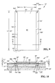
- FIG. 7 is a cross-sectional view of the walkway pad of FIG. 6 mounted to a flat roof, the cross-sectional view taken along line 7 - 7 of FIG. 6 ;
- FIG. 8 is a perspective view of yet another exemplary walkway pad of the present invention, the walkway pad including a body and two integral expansion joints;
- FIG. 9 is a top plan view of the walkway pad of FIG. 8 ;
- FIG. 10 is a cross-sectional view of the walkway pad of FIG. 9 mounted to a flat roof, the cross-sectional view taken along line 10 - 10 of FIG. 9 ;
- FIG. 11 is a perspective view of an exemplary machine of the present invention, the machine including a plurality of calendars.
- FIG. 12 is a top plan view of the plurality of calendars of FIG. 11 .
- FIG. 1 depicts a portion of flat roof 20 .
- flat roof 20 is horizontal or nearly horizontal with only a slight inclination.
- Flat or low sloped roofs, like roof 20 are generally used on commercial buildings and large residential buildings, while high sloped roofs are generally used on homes.
- Roof 20 is shown in cross-section in FIG. 4 .
- Roof 20 includes a base or deck 22 , which may be constructed of metal, wood, concrete, or another suitable material.
- Atop deck 22 , roof 20 includes an intermediate layer of insulation 24 .
- Atop insulation 24 , roof 20 includes protective membrane 26 that is designed to shield both deck 22 and insulation 24 of roof 20 from heat and moisture. Adjacent layers of roof 20 may be secured together using suitable mechanical fasteners, adhesives, or welding techniques, for example.
- the roof construction may vary and is not limited to the particular construction described and illustrated herein.
- Membrane 26 of roof 20 may be a continuous sheet of material or, as shown in FIG. 1 , membrane 26 may include multiple strips of material bonded together.
- Membrane 26 may be constructed of reinforced or unreinforced rubbers, such as ethylene-propylene-diene (EPDM) terpolymers, ethylene-propylene copolymers, or other similar olefin-type polymers, and mixtures thereof.
- An exemplary material that may be used to manufacture membrane 26 is thermoplastic polyolefin (TPO), which includes thermoplastic polymer, rubber, and a reinforcing filler.
- TPO thermoplastic polyolefin
- Equipment 28 that services the underlying building (not shown) is mounted atop roof 20 .
- Equipment 28 may be an air conditioning apparatus, an HVAC unit, an exhaust fan, a smoke hatch, a condenser unit, window washing equipment, a lightening protection unit, or another device that services the underlying building, for example.
- a plurality of walkway pads 30 have been applied atop roof 20 of FIG. 1 .
- walkway pads 30 protect roof 20 , specifically membrane 26 of roof 20 , from foot traffic.
- walkway pads 30 are placed at access points and along common traffic paths, such as along a traffic path to equipment 28 that is traveled whenever equipment 28 is serviced or repaired.
- Walkway pad 30 includes body 32 and expansion joints 34 a , 34 b , located beneath body 32 .
- Body 32 of walkway pad 30 includes top surface 40 and an opposing bottom surface 41 that faces both roof 20 and expansion joints 34 a , 34 b .
- An outer periphery of body 32 is defined by first end 42 , second end 44 , first side 46 , and second side 48 .
- body 32 of walkway pad 30 is generally rectangular in shape having length L 1 that extends from first end 42 to second end 44 and width W 1 that extends from first side 46 to second side 48 .
- Width W 1 may equal approximately 20′′ (50.8 cm), 30′′ (76.2 cm), 40′′ (101.6 cm), or more, for example, with length L 1 varying depending upon the particular application. It is also within the scope of the present invention that body 32 of walkway pad 30 may be available in other suitable shapes.
- Expansion joints 34 a , 34 b , of walkway pad 30 include top surfaces 50 a , 50 b , that face body 32 and opposing bottom surfaces 51 a , 51 b , that face roof 20 .
- each expansion joint 34 a , 34 b , of walkway pad 30 is an elongate, rectangular strip having length L 2 that is substantially equal to length L 1 of body 32 and width W 2 of approximately 4′′ (10.2 cm), 6′′ (15.2 cm), 8′′ (20.3 cm), 10′′ (25.4 cm), or more, for example.
- each expansion joint 34 a , 34 b includes first overlapping region 52 a , 52 b , where bottom surface 41 of body 32 overlaps top surface 50 a , 50 b , of expansion joint 34 a , 34 b , and second free region 54 a , 54 b , that extends outwardly from body 32 such that bottom surface 41 of body 32 does not overlap top surface 50 a , 50 b , of expansion joint 34 a , 34 b .
- each overlapping region 52 a , 52 b may be approximately 2′′ (5.1 cm), 3′′ (7.6 cm), or 4′′ (10.2 cm) wide, and each free region 54 a , 54 b , may be approximately 2′′ (5.1 cm), 3′′ (7.6 cm), or 4′′ (10.2 cm) wide, for example.
- body 32 may be secured to expansion joints 34 a , 34 b , by welding, adhering, taping, bonding, or otherwise securing bottom surface 41 of body 32 to top surfaces 50 a , 50 b , of expansion joints 34 a , 34 b , and more specifically to overlapping regions 52 a , 52 b , of top surfaces 50 a , 50 b , of expansion joints 34 a , 34 b . If body 32 is welded to expansion joints 34 a , 34 b , the components should be at about the same temperature before welding.
- walkway pad 30 may be secured to roof 20 by welding, adhering, taping, bonding, or otherwise securing bottom surfaces 51 a , 51 b , of expansion joints 34 a , 34 b , to roof 20 , and more specifically to membrane 26 of roof 20 . If expansion joints 34 a , 34 b , of walkway pad 30 are welded to membrane 26 of roof 20 , the components should be at about the same temperature before welding. According to an exemplary embodiment of the present invention, only the outer-most portion of each expansion joint 34 a , 34 b , is secured to roof 20 . Therefore, as shown in FIG.
- each expansion joint 34 a , 34 b includes outer attachment region 56 a , 56 b , where bottom surface 51 a , 51 b , is secured to membrane 26 of roof 20 , and inner free region 58 a , 58 b , where bottom surface 51 a , 51 b , is not secured to membrane 26 of roof 20 .
- each attachment region 56 a , 56 b may be approximately 1′′ (2.5 cm), 1.5′′ (3.8 cm), or 2′′ (5.1 cm) wide, for example.
- a serviceman or another user may walk across top surface 40 of body 32 from first end 42 to second end 44 .
- the user may walk across top surface 40 of body 32 to access and repair equipment 28 ( FIG. 1 ) on top of roof 20 .
- Top surface 40 of body 32 may be textured to provide traction for the user, even in wet conditions.
- bottom surface 41 of body 32 is shown hovering slightly above roof 20 , body 32 may bend under the user's weight until bottom surface 41 of body 32 contacts roof 20 .
- each expansion joint 34 a , 34 b includes a corresponding expansion region 60 a , 60 b , that is designed to deform to a greater extent than body 32 to absorb thermal movement (expansion/contraction) of body 32 .
- body 32 remains flat against roof 20 to provide a flat walking surface and an aesthetically pleasing appearance.
- expansion regions 60 a , 60 b , of expansion joints 34 a , 34 b are not directly attached to body 32 or to roof 20 . More specifically, expansion regions 60 a , 60 b , of expansion joints 34 a , 34 b , are offset from both overlapping regions 52 a , 52 b , of top surfaces 50 a , 50 b , and attachment regions 56 a , 56 b , of bottom surfaces 51 a , 51 b .
- expansion regions 60 a , 60 b , of expansion joints 34 a , 34 b are defined where free regions 54 a , 54 b , of top surfaces 50 a , 50 b , overlap free regions 58 a , 58 b , of bottom surfaces 51 a , 51 b .
- Each expansion region 60 a , 60 b may be approximately 1′′ (2.5 cm), 1.5′′ (3.8 cm), or 2′′ (5.1 cm) wide, for example.
- expansion joints 34 a , 34 b are shown extending only along first side 46 and second side 48 of body 32 , expansion regions 60 a , 60 b , of expansion joints 34 a , 34 b , may deform sufficiently to allow first end 42 , second end 44 , first side 46 , and second side 48 of body 32 to lie flat against roof 20 . It is also within the scope of the present invention that walkway pad 30 may include additional expansion joints located beneath first end 42 and/or second end 44 of body 32 , for example. However, a gap should be present between adjacent expansion joints to allow air to escape beneath body 32 when the user walks across body 32 .
- the material used to construct expansion joints 34 a , 34 b , of walkway pad 30 is more flexible and/or resilient than the material used to construct body 32 of walkway pad 30 .
- body 32 of walkway pad 30 may be constructed of a supported thermoplastic polyolefin (TPO), including thermoplastic polymer, rubber, and a reinforcing filler, some or all of which may be recycled materials.
- TPO thermoplastic polyolefin
- An exemplary body 32 includes the UltraPlyTM TPO Premium Walkway Pad, available from Firestone Building Products Company of Indianapolis, Ind.
- expansion joints 34 a , 34 b , of walkway pad 30 may be constructed of a more flexible material, such as an extruded blend of recycled rubber and thermoplastic polyolefin (RPO) or an unsupported TPO material.
- RPO thermoplastic polyolefin
- the more flexible expansion regions 60 a , 60 b , of expansion joints 34 a , 34 b are more deformable than body 32 and are able to absorb thermal movement (expansion/contraction) of body 32 , thereby reducing or eliminating buckling of body 32 .
- expansion joints 34 a , 34 b , of walkway pad 30 are thinner than body 32 of walkway pad 30 .
- thickness T 2 of each expansion joint 34 a , 34 b may be approximately 0.03′′ (0.8 mm), 0.04′′ (1.0 mm), 0.05′′ (1.3 mm), 0.06′′ (1.5 mm), or more, while thickness T 1 of body 32 may be as small as approximately 0.06′′ (1.5 mm), 0.10′′ (2.5 mm), 0.15′′ (3.8 mm), 0.20′′ (5.1 mm), 0.25′′ (6.4 mm), or 0.30′′ (7.6 mm) and as large as approximately 0.35′′ (8.9 mm), 0.40′′ (10.2 mm), 0.45′′ (11.4 mm), or 0.50′′ (12.7 mm).
- each expansion joint 34 a , 34 b may be about 10%, 20%, 30%, 40%, or 50% of thickness T 1 of body 32 .
- the thinner expansion regions 60 a , 60 b , of expansion joints 34 a , 34 b are more deformable than the thicker body 32 and are able to absorb thermal movement (expansion/contraction) of body 32 , thereby reducing or eliminating buckling of body 32 .
- expansion joints 34 a , 34 b , of walkway pad 30 are dark in color.
- expansion joints 34 a , 34 b may be gray or black in color.
- the dark expansion regions 60 a , 60 b , of expansion joints 34 a , 34 b absorb more heat than expansion joints 34 a , 34 b , that are light in color, making expansion regions 60 a , 60 b , of expansion joints 34 a , 34 b , more likely to buckle and deform than body 32 .
- the material used to construct expansion joints 34 a , 34 b , of walkway pad 30 may be more flexible than the material used to construct body 32 of walkway pad 30
- expansion joints 34 a , 34 b , of walkway pad 30 may be thinner than body 32 of walkway pad 30
- expansion joints 34 a , 34 b , of walkway pad 30 may be dark in color.
- Walkway pad 30 ′ is substantially similar to walkway pad 30 of FIGS. 2-4 , with like reference numerals indicating like elements, except as described below.
- walkway pad 30 ′ includes body 32 ′ and a single expansion joint 34 ′ located beneath body 32 ′. The use of only one expansion joint 34 ′ may reduce the cost of manufacturing walkway pad 30 ′ compared to walkway pad 30 having two expansion joints 34 a , 34 b ( FIG. 2 ).
- expansion joint 34 ′ includes first overlapping region 52 ′ where bottom surface 41 ′ of body 32 ′ overlaps top surface 50 ′ of expansion joint 34 ′ and second free region 54 ′ that extends outwardly from body 32 ′ such that bottom surface 41 ′ of body 32 ′ does not overlap top surface 50 ′ of expansion joint 34 ′.
- body 32 ′ may be secured to expansion joints 34 ′ by welding, adhering, taping, bonding, or otherwise securing bottom surface 41 ′ of body 32 ′ to top surface 50 ′ of expansion joint 34 ′, and more specifically to overlapping region 52 ′ of top surface 50 ′ of expansion joint 34 ′. If body 32 ′ is welded to expansion joint 34 ′, the components should be at about the same temperature before welding. Depending on total width W 2 ′ of expansion joint 34 ′, overlapping region 52 ′ may be approximately 1′′ (2.5 cm), 1.5′′ (3.8 cm), or 2′′ (5.1 cm) wide, for example.
- walkway pad 30 ′ may be secured to roof 20 ′ by welding, adhering, taping, bonding, or otherwise securing bottom surface 51 ′ of expansion joint 34 ′ to roof 20 ′, and more specifically to membrane 26 ′ of roof 20 ′. If expansion joint 34 ′ of walkway pad 30 ′ is welded to membrane 26 ′ of roof 20 ′, the components should be at about the same temperature before welding. According to an exemplary embodiment of the present invention, only the outer-most portion of expansion joint 34 ′ is secured to roof 20 ′. Therefore, as shown in FIG.
- expansion joint 34 ′ includes outer attachment region 56 ′ where bottom surface 51 ′ is secured to membrane 26 ′ of roof 20 ′, and inner free region 58 ′ where bottom surface 51 ′ is not secured to membrane 26 ′ of roof 20 ′.
- attachment region 56 ′ may be approximately 1′′ (2.5 cm), 1.5′′ (3.8 cm), or 2′′ (5.1 cm) wide, for example.
- walkway pad 30 ′ may be secured to roof 20 ′ by welding, adhering, taping, bonding, or otherwise securing first side 46 ′ of body 32 ′ to membrane 26 ′ of roof 20 ′.
- first side 46 ′ of body 32 ′ includes attachment region 70 ′ where bottom surface 41 ′ of body 32 ′ is secured to membrane 26 ′ of roof 20 ′.
- expansion joint 34 ′ includes expansion region 60 ′ that is designed to deform to a greater extent than body 32 ′ to absorb thermal movement (expansion/contraction) of body 32 ′. As a result, body 32 ′ remains flat against roof 20 ′ to provide a flat walking surface and an aesthetically pleasing appearance.
- expansion region 60 ′ of expansion joint 34 ′ is not directly attached to body 32 ′ or to roof 20 ′. More specifically, expansion region 60 ′ of expansion joint 34 ′ is offset from both overlapping region 52 ′ of top surface 50 ′ and attachment region 56 ′ of bottom surface 51 ′. Thus, expansion region 60 ′ of expansion joint 34 ′ is defined where free region 54 ′ of top surface 50 ′ overlaps free region 58 ′ of bottom surface 51 ′. To account for the presence of only a single expansion joint 34 ′, expansion region 60 ′ of expansion joint 34 ′ may be about twice as wide as each individual expansion region 60 a , 60 b , when using two expansion joints 34 a , 34 b ( FIGS. 2-5 ).
- expansion region 60 ′ of walkway pad 30 ′ may be approximately 2′′ (5.1 cm), 3′′ (7.6 cm), or 4′′ (10.2 cm) wide, while each individual expansion region 60 a , 60 b , of walkway pad 30 ( FIGS. 2-5 ) may be approximately 1′′ (2.5 cm), 1.5′′ (3.8 cm), or 2′′ (5.1 cm) wide.
- expansion joint 34 ′ of walkway pad 30 ′ may be more flexible than the material used to construct body 32 ′ of walkway pad 30 ′, expansion joint 34 ′ may be thinner than body 32 ′ of walkway pad 30 ′, and/or expansion joint 34 ′ may be dark in color.
- Walkway pad 30 ′′ is substantially similar to walkway pad 30 of FIGS. 2-4 and walkway pad 30 ′ of FIGS. 5-7 , with like reference numerals indicating like elements, except as described below.
- walkway pad 30 ′′ is an integral structure, with expansion joints 34 a ′′, 34 b ′′, being integrally connected to body 32 ′′.
- expansion joints 34 a ′′, 34 b ′′ extend outwardly from body 32 ′′. More particularly, expansion joint 34 a ′′ extends outwardly from first side 46 ′′ of body 32 ′′ and expansion joint 34 b ′′ extends outwardly from second side 48 ′′ of body 32 ′′. Although expansion joints 34 a ′′, 34 b ′′, are shown extending along first side 46 ′′ and second side 48 ′′ of body 32 ′′, the integral walkway pad 30 ′′ may include only a single expansion joint (as in FIGS. 5-7 ), or the integral walkway pad 30 ′′ may include additional expansion joints that extend from first end 42 ′′ and/or second end 44 ′′ of body 32 ′′, for example.
- walkway pad 30 ′′ may be secured to roof 20 ′′ by welding, adhering, taping, bonding, or otherwise securing bottom surfaces 51 a ′′, 51 b ′′, of expansion joints 34 a ′′, 34 b ′′, to roof 20 ′′, and more specifically to membrane 26 ′′ of roof 20 ′′. If expansion joints 34 a ′′, 34 b ′′, of walkway pad 30 ′′ are welded to membrane 26 ′′ of roof 20 ′′, the components should be at about the same temperature before welding. According to an exemplary embodiment of the present invention, only the outer-most portion of each expansion joint 34 a ′′, 34 b ′′, is secured to roof 20 ′′. Therefore, as shown in FIG.
- each expansion joint 34 a ′′, 34 b ′′ includes outer attachment region 56 a ′′, 56 b ′′, where bottom surface 51 a ′′, 51 b ′′, is secured to membrane 26 ′′ of roof 20 ′′, and inner free region 58 a ′′, 58 b ′′, where bottom surface 51 a ′′, 51 b ′′, is not secured to membrane 26 ′′ of roof 20 ′′.
- each attachment region 56 a ′′, 56 b ′′ may be approximately 1′′ (2.5 cm), 1.5′′ (3.8 cm), or 2′′ (5.1 cm) wide, for example.
- bottom surface 41 ′′ of body 32 ′′ may rest directly against roof 20 ′′ rather than hovering slightly above roof 20 ′′.
- each expansion joint 34 a ′′, 34 b ′′ includes a corresponding expansion region 60 a ′′, 60 b ′′, that is designed to deform to a greater extent than body 32 ′′ to absorb thermal movement (expansion/contraction) of body 32 ′′.
- body 32 ′′ remains flat against roof 20 ′′ to provide a flat walking surface and an aesthetically pleasing appearance.
- expansion regions 60 a ′′, 60 b ′′, of expansion joints 34 a ′′, 34 b ′′ are not directly attached to body 32 ′′ or to roof 20 ′′. More specifically, expansion regions 60 a ′′, 60 b ′′, of expansion joints 34 a ′′, 34 b ′′, are offset from body 32 ′′ and from attachment regions 56 a ′′, 56 b ′′, of bottom surfaces 51 a ′′, 51 b ′′. Thus, expansion regions 60 a ′′, 60 b ′′, of expansion joints 34 a ′′, 34 b ′′, include free regions 58 a ′′, 58 b ′′, of bottom surfaces 51 a ′′, 51 b ′′. Each expansion region 60 a ′′, 60 b ′′, may be approximately 1′′ (2.5 cm), 1.5′′ (3.8 cm), or 2′′ (5.1 cm) wide, for example.
- expansion joints 34 a ′′, 34 b ′′, of walkway pad 30 ′′ may be the same as the material used to construct body 32 ′′ of walkway pad 30 ′′.
- expansion regions 60 a ′′, 60 b ′′, of expansion joints 34 a ′′, 34 b ′′ may still accommodate thermal movement (expansion/contraction) of body 32 ′′ by providing expansion joints 34 a ′′, 34 b ′′, that are thinner than body 32 ′′ of walkway pad 30 ′′ and/or dark in color.
- exemplary machine 100 is provided for manufacturing the integral walkway pad 30 ′′ of FIGS. 8-10 .
- Machine 100 includes die 102 , first cylindrical calendar 104 , second cylindrical calendar 106 , third cylindrical calendar 108 , and conveyor 110 .
- second calendar 106 includes an annular recess 112 in its outer surface.
- Second calendar 106 cooperates with first calendar 104 to define a T-shaped gap 114 therebetween, and second calendar 106 cooperates with third calendar 108 to define a substantially identical T-shaped gap 116 therebetween.
- a melted material such as a melted blend of rubber and thermoplastic polyolefin (RPO)
- RPO thermoplastic polyolefin
- the material flows around second calendar 106 and upwardly through gap 116 between second calendar 106 and third calendar 108 .
- the material flows around third calendar 108 and along conveyor 110 and is cut to a desired length L 1 ′′, L 2 ′′ ( FIG. 9 ).
- the resulting product that exits machine 100 is T-shaped in cross-section, like gaps 114 , 116 .
- Each body was a rectangular TPO Eco Walkway Pad available from Firestone Building Products Company of Indianapolis, Ind. Each body had a thickness of 140 mils (3.6 mm).
- the first walkway pad included two expansion joints secured beneath the body, like walkway pad 30 of FIGS. 2-4 .
- Each expansion joint was an elongate strip of rubber and thermoplastic polyolefin (RPO) having a thickness of 38 mils (1.0 mm).
- the expansion joints were black in color.
- the expansion region of each expansion joint was 1.5′′ wide (3.8 cm).
- the second walkway pad included two expansion joints secured beneath the body, like walkway pad 30 of FIGS. 2-4 .
- Each expansion joint was an elongate strip of rubber and thermoplastic polyolefin (RPO) having a thickness of 38 mils (1.0 mm).
- the expansion joints were gray in color.
- the expansion region of each expansion joint was 1.5′′ wide (3.8 cm).
- the third walkway pad was a control sample that did not include an expansion joint. Rather, the body of the third walkway pad was attached directly to a roof membrane.
- the three walkway pads were secured to a roof membrane and placed outdoors in sunlight for 6 hours and 23 minutes. At the start of the test, the ambient temperature was 67° F. At the end of the test, the ambient temperature had increased to 93° F.
- the bodies of the first and second walkway pads lacked any visible buckling. Buckling was only observed on the expansion joints of the first and second walkway pads.
- the body of the third walkway pad included visible crests at both ends, including one crest that was about 1.19′′ (3.0 cm) tall.
- the temperature of the black expansion joint of the first walkway pad was measured using an infrared thermometer to be about 5° warmer than the gray expansion joint of the second walkway pad.
- the test was repeated a second time.
- the first and second walkway pads were placed outdoors in sunlight for 4 hours and 25 minutes. Again, the bodies of the first and second walkway pads lacked any visible buckling.
- Example 1 Another walkway pad was constructed having expansion joints that differed in material, thickness, and color from those of Example 1.
- the body of the walkway pad was the same as Example 1—a rectangular TPO Eco Walkway Pad available from Firestone Building Products Company of Indianapolis, Ind., having a thickness of 140 mils (3.6 mm).
- the walkway pad included two expansion joints secured beneath the body, like walkway pad 30 of FIGS. 2-4 .
- Each expansion joint was an elongate strip of unsupported TPO having a thickness of 60 mils (1.5 mm)—about twice as thick as the expansion joints of Example 1.
- the expansion region of each expansion joint was 3′′ (7.6 cm) wide—twice as wide as the expansion regions of Example 1.
- a first expansion joint was secured beneath a first side of the body.
- the first expansion joint was painted black in color near a first end of the body and gray in color near a second end of the body.
- a second expansion joint was secured beneath a second side of the body. The second expansion joint was left white in color.
- the walkway pad was secured to a roof membrane and placed outdoors in sunlight for 4 hours and 35 minutes. At the start of the test, the ambient temperature was 72° F. At the end of the test, the ambient temperature had increased to 85° F.
- the body included a very slight crest near the white expansion joint, but not near the black/gray expansion joint. Measurable buckling was observed on the expansion joints themselves. Crests on the black/gray expansion joint grew by about 0.38′′ (9.7 mm)-0.63′′ (16.0 mm), while crests on the white expansion joint grew by about 0.06′′ (1.5 mm)-0.13′′ (3.3 mm).
- FIGS. 5-7 Another walkway pad was constructed having only a single expansion joint, like walkway pad 30 ′ of FIGS. 5-7 .
- the body of the walkway pad was the same as Examples 1 and 2—a rectangular TPO Eco Walkway Pad available from Firestone Building Products Company of Indianapolis, Ind., having a thickness of 140 mils (3.6 mm).
- the expansion joint was an elongate strip of rubber and thermoplastic polyolefin (RPO) having a thickness of 38 mils (1.0 mm). However, unlike Example 1, the expansion region of the single expansion joint was 3′′ (7.6 cm) wide.
- RPO thermoplastic polyolefin
- the expansion joint and the opposite side of the body were secured to a roof membrane.
- the walkway pad was then placed outdoors in sunlight for 4 hours and 35 minutes.
- the ambient temperature was 72° F.
- the ambient temperature had increased to 85° F.
- the body of the walkway pad included small visible crests at both ends, including one crest that grew from about 0′′ (0 mm) tall to about 0.06′′ (1.5 mm) tall and another crest that grew from about 0′′(0 mm) tall to about 0.13′′ (3.3 mm) tall.
- the expansion joint itself included crests that grew from about 0.25′′ (6.4 mm) tall to about 0.69′′ (17.5 mm) tall.
Landscapes
- Engineering & Computer Science (AREA)
- Architecture (AREA)
- Civil Engineering (AREA)
- Structural Engineering (AREA)
- Road Paving Structures (AREA)
- Roof Covering Using Slabs Or Stiff Sheets (AREA)
Abstract
Description
Claims (20)
Priority Applications (1)
| Application Number | Priority Date | Filing Date | Title |
|---|---|---|---|
| US12/829,723 US9828778B2 (en) | 2010-07-02 | 2010-07-02 | Walkway pad with expansion joints |
Applications Claiming Priority (1)
| Application Number | Priority Date | Filing Date | Title |
|---|---|---|---|
| US12/829,723 US9828778B2 (en) | 2010-07-02 | 2010-07-02 | Walkway pad with expansion joints |
Publications (2)
| Publication Number | Publication Date |
|---|---|
| US20120000152A1 US20120000152A1 (en) | 2012-01-05 |
| US9828778B2 true US9828778B2 (en) | 2017-11-28 |
Family
ID=45398640
Family Applications (1)
| Application Number | Title | Priority Date | Filing Date |
|---|---|---|---|
| US12/829,723 Active 2033-10-08 US9828778B2 (en) | 2010-07-02 | 2010-07-02 | Walkway pad with expansion joints |
Country Status (1)
| Country | Link |
|---|---|
| US (1) | US9828778B2 (en) |
Families Citing this family (1)
| Publication number | Priority date | Publication date | Assignee | Title |
|---|---|---|---|---|
| US20200032512A1 (en) * | 2015-11-17 | 2020-01-30 | The Shredded Tire, Inc. | Environmentally responsible insulating construction blocks and structures |
Citations (23)
| Publication number | Priority date | Publication date | Assignee | Title |
|---|---|---|---|---|
| US3307306A (en) * | 1961-07-28 | 1967-03-07 | Adsure Inc | Insulation blanket structure |
| US3484405A (en) * | 1965-12-13 | 1969-12-16 | Polymer Corp | Solid adhesive polymer compositions |
| US3581450A (en) * | 1969-04-18 | 1971-06-01 | Francis J Patry | Expansion joint cover |
| US3643388A (en) * | 1968-01-09 | 1972-02-22 | Carlisle Corp | Flexible expansion joint for structures |
| US3713263A (en) * | 1971-05-07 | 1973-01-30 | W Mullen | Expansion joints for roofs |
| US3724155A (en) * | 1970-01-29 | 1973-04-03 | Silent Channel Prod Ltd | Method for the sealing of roof or other structures |
| US3810707A (en) * | 1969-08-22 | 1974-05-14 | Minnesota Mining & Mfg | Joint structure and method |
| US4601935A (en) * | 1985-05-06 | 1986-07-22 | Gencorp Inc. | EPDM laminate |
| US4674245A (en) * | 1984-03-19 | 1987-06-23 | Diversitech Corporation | Roof walkway panel |
| US4680909A (en) * | 1984-09-11 | 1987-07-21 | Industrial Research Development, Inc. | Roofing system |
| US4817963A (en) * | 1987-03-31 | 1989-04-04 | Hot Melt Systems Limited | Hot melt strip seam sealing method |
| US4848044A (en) * | 1988-07-14 | 1989-07-18 | Manville Corporation | Expansion joint cover |
| US5085022A (en) * | 1990-01-30 | 1992-02-04 | Therm-All, Inc. | Building insulation |
| US5095068A (en) * | 1983-04-05 | 1992-03-10 | Ashland Oil, Inc. | Adhesive of butyl rubber, curing agent, c-black and tackifier |
| US5563217A (en) * | 1994-03-18 | 1996-10-08 | Bridgestone/Firestone, Inc. | Adhesive tape compositions |
| US5800891A (en) * | 1997-01-23 | 1998-09-01 | Bridgestone/Firestone, Inc. | Bonding pad for nonpenetrating roof membrane fastening system |
| US5859114A (en) * | 1994-10-27 | 1999-01-12 | Bridgestone/Firstone, Inc. | Adhesive tape compositions and method for covering roofs |
| US6071996A (en) * | 1997-08-08 | 2000-06-06 | Bridgestone/Firestone, Inc. | EPDM walkway pad compositions and uses therefor |
| US6491471B1 (en) * | 1997-02-07 | 2002-12-10 | Robert J. Susinskas | Reinforced EPDM walkways |
| US20050000179A1 (en) * | 2001-12-18 | 2005-01-06 | Hornsby Eric Rowles | Liner panels |
| US7000360B1 (en) | 1996-02-23 | 2006-02-21 | Bfs Diversified Products, Llc | Self-adhering walkway pads for roofing membranes and method for the application thereof to roofs |
| US20070261342A1 (en) * | 2006-04-25 | 2007-11-15 | Building Materials Investment Corporation | Factory fabricated expansion joint cover |
| US20100119820A1 (en) * | 2007-03-01 | 2010-05-13 | Stefan Ultsch | Fluorinated polymer system |
-
2010
- 2010-07-02 US US12/829,723 patent/US9828778B2/en active Active
Patent Citations (23)
| Publication number | Priority date | Publication date | Assignee | Title |
|---|---|---|---|---|
| US3307306A (en) * | 1961-07-28 | 1967-03-07 | Adsure Inc | Insulation blanket structure |
| US3484405A (en) * | 1965-12-13 | 1969-12-16 | Polymer Corp | Solid adhesive polymer compositions |
| US3643388A (en) * | 1968-01-09 | 1972-02-22 | Carlisle Corp | Flexible expansion joint for structures |
| US3581450A (en) * | 1969-04-18 | 1971-06-01 | Francis J Patry | Expansion joint cover |
| US3810707A (en) * | 1969-08-22 | 1974-05-14 | Minnesota Mining & Mfg | Joint structure and method |
| US3724155A (en) * | 1970-01-29 | 1973-04-03 | Silent Channel Prod Ltd | Method for the sealing of roof or other structures |
| US3713263A (en) * | 1971-05-07 | 1973-01-30 | W Mullen | Expansion joints for roofs |
| US5095068A (en) * | 1983-04-05 | 1992-03-10 | Ashland Oil, Inc. | Adhesive of butyl rubber, curing agent, c-black and tackifier |
| US4674245A (en) * | 1984-03-19 | 1987-06-23 | Diversitech Corporation | Roof walkway panel |
| US4680909A (en) * | 1984-09-11 | 1987-07-21 | Industrial Research Development, Inc. | Roofing system |
| US4601935A (en) * | 1985-05-06 | 1986-07-22 | Gencorp Inc. | EPDM laminate |
| US4817963A (en) * | 1987-03-31 | 1989-04-04 | Hot Melt Systems Limited | Hot melt strip seam sealing method |
| US4848044A (en) * | 1988-07-14 | 1989-07-18 | Manville Corporation | Expansion joint cover |
| US5085022A (en) * | 1990-01-30 | 1992-02-04 | Therm-All, Inc. | Building insulation |
| US5563217A (en) * | 1994-03-18 | 1996-10-08 | Bridgestone/Firestone, Inc. | Adhesive tape compositions |
| US5859114A (en) * | 1994-10-27 | 1999-01-12 | Bridgestone/Firstone, Inc. | Adhesive tape compositions and method for covering roofs |
| US7000360B1 (en) | 1996-02-23 | 2006-02-21 | Bfs Diversified Products, Llc | Self-adhering walkway pads for roofing membranes and method for the application thereof to roofs |
| US5800891A (en) * | 1997-01-23 | 1998-09-01 | Bridgestone/Firestone, Inc. | Bonding pad for nonpenetrating roof membrane fastening system |
| US6491471B1 (en) * | 1997-02-07 | 2002-12-10 | Robert J. Susinskas | Reinforced EPDM walkways |
| US6071996A (en) * | 1997-08-08 | 2000-06-06 | Bridgestone/Firestone, Inc. | EPDM walkway pad compositions and uses therefor |
| US20050000179A1 (en) * | 2001-12-18 | 2005-01-06 | Hornsby Eric Rowles | Liner panels |
| US20070261342A1 (en) * | 2006-04-25 | 2007-11-15 | Building Materials Investment Corporation | Factory fabricated expansion joint cover |
| US20100119820A1 (en) * | 2007-03-01 | 2010-05-13 | Stefan Ultsch | Fluorinated polymer system |
Also Published As
| Publication number | Publication date |
|---|---|
| US20120000152A1 (en) | 2012-01-05 |
Similar Documents
| Publication | Publication Date | Title |
|---|---|---|
| JP2730911B2 (en) | EPDM composite material for flame resistant roof | |
| US9611647B2 (en) | Thermoplastic single ply membrane | |
| KR101005542B1 (en) | Multifunctional building insulation waterproof composite sheet and composite waterproof structure using the same | |
| KR100971254B1 (en) | Self-adhesive insulation sheet and waterproof method using the same | |
| CA2969081C (en) | Spaced vent for metal roofs | |
| WO2006052942A2 (en) | Roof underlayment | |
| JPH01318646A (en) | Sealing strip used for finishing ridge of roof | |
| US20100196647A1 (en) | Shingle sealant and adhesive | |
| US20110154751A1 (en) | Light Transmitting Roofing Panel | |
| KR101553393B1 (en) | Self adhesive combination waterproofing sheet, the overlapping connection structure using the self adhesive combination waterproofing sheet and the method thereof | |
| US3355846A (en) | Roof expansion joint | |
| US4071994A (en) | Expansion joint for roofs and the like | |
| US20030230040A1 (en) | Waterproof-sheet type of roofing shingle | |
| US9828778B2 (en) | Walkway pad with expansion joints | |
| JP2009167728A (en) | Sheet-waterproofing roof | |
| US20070261342A1 (en) | Factory fabricated expansion joint cover | |
| CA2670548A1 (en) | Tpo roofing membrane fastening system and method | |
| US20030082387A1 (en) | Insulation facing material z-fold area coating | |
| CN112482639A (en) | Assembled roof | |
| PL1953306T5 (en) | A multilayer roofing element and a method for manufacturing the same | |
| JP7034460B2 (en) | Roof waterproof repair system | |
| KR101236565B1 (en) | Thermoplastic polyolefin sheet integrated deck panel and manufacturing method thereof | |
| CN203080811U (en) | Waterproof roof | |
| JP4685592B2 (en) | Waterproof structure | |
| CN214169678U (en) | Waterproofing membrane and roofing system |
Legal Events
| Date | Code | Title | Description |
|---|---|---|---|
| AS | Assignment |
Owner name: FIRESTONE BUILDING PRODUCTS COMPANY, LLC, INDIANA Free format text: ASSIGNMENT OF ASSIGNORS INTEREST;ASSIGNORS:WATKINS, CARL E., JR.;PENG, RICHARD L.;SIGNING DATES FROM 20100723 TO 20100802;REEL/FRAME:024787/0344 |
|
| STCF | Information on status: patent grant |
Free format text: PATENTED CASE |
|
| MAFP | Maintenance fee payment |
Free format text: PAYMENT OF MAINTENANCE FEE, 4TH YEAR, LARGE ENTITY (ORIGINAL EVENT CODE: M1551); ENTITY STATUS OF PATENT OWNER: LARGE ENTITY Year of fee payment: 4 |
|
| AS | Assignment |
Owner name: HOLCIM TECHNOLOGY LTD, SWITZERLAND Free format text: ASSIGNMENT OF ASSIGNORS INTEREST;ASSIGNOR:FIRESTONE BUILDING PRODUCTS COMPANY, LLC;REEL/FRAME:060920/0869 Effective date: 20220404 |
|
| MAFP | Maintenance fee payment |
Free format text: PAYMENT OF MAINTENANCE FEE, 8TH YEAR, LARGE ENTITY (ORIGINAL EVENT CODE: M1552); ENTITY STATUS OF PATENT OWNER: LARGE ENTITY Year of fee payment: 8 |
|
| AS | Assignment |
Owner name: AMRIZE TECHNOLOGY SWITZERLAND LLC, SWITZERLAND Free format text: ASSIGNMENT OF ASSIGNORS INTEREST;ASSIGNOR:HOLCIM TECHNOLOGY LTD;REEL/FRAME:073030/0406 Effective date: 20250812 |