US9827677B1 - Robotic device with coordinated sweeping tool and shovel tool - Google Patents
Robotic device with coordinated sweeping tool and shovel tool Download PDFInfo
- Publication number
- US9827677B1 US9827677B1 US15/155,368 US201615155368A US9827677B1 US 9827677 B1 US9827677 B1 US 9827677B1 US 201615155368 A US201615155368 A US 201615155368A US 9827677 B1 US9827677 B1 US 9827677B1
- Authority
- US
- United States
- Prior art keywords
- robotic device
- tool
- linkage
- actuated
- end effector
- Prior art date
- Legal status (The legal status is an assumption and is not a legal conclusion. Google has not performed a legal analysis and makes no representation as to the accuracy of the status listed.)
- Expired - Fee Related, expires
Links
Images


Classifications
-
- B—PERFORMING OPERATIONS; TRANSPORTING
- B25—HAND TOOLS; PORTABLE POWER-DRIVEN TOOLS; MANIPULATORS
- B25J—MANIPULATORS; CHAMBERS PROVIDED WITH MANIPULATION DEVICES
- B25J9/00—Program-controlled manipulators
- B25J9/16—Program controls
- B25J9/1679—Program controls characterised by the tasks executed
- B25J9/1682—Dual arm manipulator; Coordination of several manipulators
-
- A—HUMAN NECESSITIES
- A47—FURNITURE; DOMESTIC ARTICLES OR APPLIANCES; COFFEE MILLS; SPICE MILLS; SUCTION CLEANERS IN GENERAL
- A47L—DOMESTIC WASHING OR CLEANING; SUCTION CLEANERS IN GENERAL
- A47L11/00—Machines for cleaning floors, carpets, furniture, walls, or wall coverings
- A47L11/24—Floor-sweeping machines, motor-driven
-
- A—HUMAN NECESSITIES
- A47—FURNITURE; DOMESTIC ARTICLES OR APPLIANCES; COFFEE MILLS; SPICE MILLS; SUCTION CLEANERS IN GENERAL
- A47L—DOMESTIC WASHING OR CLEANING; SUCTION CLEANERS IN GENERAL
- A47L11/00—Machines for cleaning floors, carpets, furniture, walls, or wall coverings
- A47L11/40—Parts or details of machines not provided for in groups A47L11/02 - A47L11/38, or not restricted to one of these groups, e.g. handles, arrangements of switches, skirts, buffers, levers
- A47L11/4011—Regulation of the cleaning machine by electric means; Control systems and remote control systems therefor
-
- A—HUMAN NECESSITIES
- A47—FURNITURE; DOMESTIC ARTICLES OR APPLIANCES; COFFEE MILLS; SPICE MILLS; SUCTION CLEANERS IN GENERAL
- A47L—DOMESTIC WASHING OR CLEANING; SUCTION CLEANERS IN GENERAL
- A47L11/00—Machines for cleaning floors, carpets, furniture, walls, or wall coverings
- A47L11/40—Parts or details of machines not provided for in groups A47L11/02 - A47L11/38, or not restricted to one of these groups, e.g. handles, arrangements of switches, skirts, buffers, levers
- A47L11/4052—Movement of the tools or the like perpendicular to the cleaning surface
- A47L11/4055—Movement of the tools or the like perpendicular to the cleaning surface for lifting the tools to a non-working position
-
- A—HUMAN NECESSITIES
- A47—FURNITURE; DOMESTIC ARTICLES OR APPLIANCES; COFFEE MILLS; SPICE MILLS; SUCTION CLEANERS IN GENERAL
- A47L—DOMESTIC WASHING OR CLEANING; SUCTION CLEANERS IN GENERAL
- A47L11/00—Machines for cleaning floors, carpets, furniture, walls, or wall coverings
- A47L11/40—Parts or details of machines not provided for in groups A47L11/02 - A47L11/38, or not restricted to one of these groups, e.g. handles, arrangements of switches, skirts, buffers, levers
- A47L11/4061—Steering means; Means for avoiding obstacles; Details related to the place where the driver is accommodated
-
- B—PERFORMING OPERATIONS; TRANSPORTING
- B25—HAND TOOLS; PORTABLE POWER-DRIVEN TOOLS; MANIPULATORS
- B25J—MANIPULATORS; CHAMBERS PROVIDED WITH MANIPULATION DEVICES
- B25J11/00—Manipulators not otherwise provided for
- B25J11/008—Manipulators for service tasks
-
- B—PERFORMING OPERATIONS; TRANSPORTING
- B25—HAND TOOLS; PORTABLE POWER-DRIVEN TOOLS; MANIPULATORS
- B25J—MANIPULATORS; CHAMBERS PROVIDED WITH MANIPULATION DEVICES
- B25J11/00—Manipulators not otherwise provided for
- B25J11/008—Manipulators for service tasks
- B25J11/0085—Cleaning
-
- B—PERFORMING OPERATIONS; TRANSPORTING
- B25—HAND TOOLS; PORTABLE POWER-DRIVEN TOOLS; MANIPULATORS
- B25J—MANIPULATORS; CHAMBERS PROVIDED WITH MANIPULATION DEVICES
- B25J15/00—Gripping heads and other end effectors
- B25J15/0014—Gripping heads and other end effectors having fork, comb or plate shaped means for engaging the lower surface on a object to be transported
-
- B—PERFORMING OPERATIONS; TRANSPORTING
- B25—HAND TOOLS; PORTABLE POWER-DRIVEN TOOLS; MANIPULATORS
- B25J—MANIPULATORS; CHAMBERS PROVIDED WITH MANIPULATION DEVICES
- B25J15/00—Gripping heads and other end effectors
- B25J15/0019—End effectors other than grippers
-
- B—PERFORMING OPERATIONS; TRANSPORTING
- B25—HAND TOOLS; PORTABLE POWER-DRIVEN TOOLS; MANIPULATORS
- B25J—MANIPULATORS; CHAMBERS PROVIDED WITH MANIPULATION DEVICES
- B25J15/00—Gripping heads and other end effectors
- B25J15/0052—Gripping heads and other end effectors multiple gripper units or multiple end effectors
- B25J15/0066—Gripping heads and other end effectors multiple gripper units or multiple end effectors with different types of end effectors, e.g. gripper and welding gun
-
- B—PERFORMING OPERATIONS; TRANSPORTING
- B25—HAND TOOLS; PORTABLE POWER-DRIVEN TOOLS; MANIPULATORS
- B25J—MANIPULATORS; CHAMBERS PROVIDED WITH MANIPULATION DEVICES
- B25J15/00—Gripping heads and other end effectors
- B25J15/02—Gripping heads and other end effectors servo-actuated
-
- B—PERFORMING OPERATIONS; TRANSPORTING
- B25—HAND TOOLS; PORTABLE POWER-DRIVEN TOOLS; MANIPULATORS
- B25J—MANIPULATORS; CHAMBERS PROVIDED WITH MANIPULATION DEVICES
- B25J5/00—Manipulators mounted on wheels or on carriages
- B25J5/007—Manipulators mounted on wheels or on carriages mounted on wheels
-
- B—PERFORMING OPERATIONS; TRANSPORTING
- B25—HAND TOOLS; PORTABLE POWER-DRIVEN TOOLS; MANIPULATORS
- B25J—MANIPULATORS; CHAMBERS PROVIDED WITH MANIPULATION DEVICES
- B25J9/00—Program-controlled manipulators
- B25J9/0084—Program-controlled manipulators comprising a plurality of manipulators
- B25J9/0087—Dual arms
-
- B—PERFORMING OPERATIONS; TRANSPORTING
- B25—HAND TOOLS; PORTABLE POWER-DRIVEN TOOLS; MANIPULATORS
- B25J—MANIPULATORS; CHAMBERS PROVIDED WITH MANIPULATION DEVICES
- B25J9/00—Program-controlled manipulators
- B25J9/02—Program-controlled manipulators characterised by movement of the arms, e.g. cartesian coordinate type
- B25J9/04—Program-controlled manipulators characterised by movement of the arms, e.g. cartesian coordinate type by rotating at least one arm, excluding the head movement itself, e.g. cylindrical coordinate type or polar coordinate type
- B25J9/046—Revolute coordinate type
-
- B—PERFORMING OPERATIONS; TRANSPORTING
- B25—HAND TOOLS; PORTABLE POWER-DRIVEN TOOLS; MANIPULATORS
- B25J—MANIPULATORS; CHAMBERS PROVIDED WITH MANIPULATION DEVICES
- B25J9/00—Program-controlled manipulators
- B25J9/16—Program controls
- B25J9/1694—Program controls characterised by use of sensors other than normal servo-feedback from position, speed or acceleration sensors, perception control, multi-sensor controlled systems, sensor fusion
-
- G—PHYSICS
- G05—CONTROLLING; REGULATING
- G05D—SYSTEMS FOR CONTROLLING OR REGULATING NON-ELECTRIC VARIABLES
- G05D1/00—Control of position, course, altitude or attitude of land, water, air or space vehicles, e.g. using automatic pilots
- G05D1/02—Control of position or course in two dimensions
- G05D1/021—Control of position or course in two dimensions specially adapted to land vehicles
-
- A—HUMAN NECESSITIES
- A47—FURNITURE; DOMESTIC ARTICLES OR APPLIANCES; COFFEE MILLS; SPICE MILLS; SUCTION CLEANERS IN GENERAL
- A47L—DOMESTIC WASHING OR CLEANING; SUCTION CLEANERS IN GENERAL
- A47L2201/00—Robotic cleaning machines, i.e. with automatic control of the travelling movement or the cleaning operation
-
- G—PHYSICS
- G05—CONTROLLING; REGULATING
- G05B—CONTROL OR REGULATING SYSTEMS IN GENERAL; FUNCTIONAL ELEMENTS OF SUCH SYSTEMS; MONITORING OR TESTING ARRANGEMENTS FOR SUCH SYSTEMS OR ELEMENTS
- G05B2219/00—Program-control systems
- G05B2219/30—Nc systems
- G05B2219/39—Robotics, robotics to robotics hand
- G05B2219/39121—Two manipulators operate on same object
-
- G05D2201/0203—
-
- Y—GENERAL TAGGING OF NEW TECHNOLOGICAL DEVELOPMENTS; GENERAL TAGGING OF CROSS-SECTIONAL TECHNOLOGIES SPANNING OVER SEVERAL SECTIONS OF THE IPC; TECHNICAL SUBJECTS COVERED BY FORMER USPC CROSS-REFERENCE ART COLLECTIONS [XRACs] AND DIGESTS
- Y10—TECHNICAL SUBJECTS COVERED BY FORMER USPC
- Y10S—TECHNICAL SUBJECTS COVERED BY FORMER USPC CROSS-REFERENCE ART COLLECTIONS [XRACs] AND DIGESTS
- Y10S901/00—Robots
- Y10S901/01—Mobile robot
-
- Y—GENERAL TAGGING OF NEW TECHNOLOGICAL DEVELOPMENTS; GENERAL TAGGING OF CROSS-SECTIONAL TECHNOLOGIES SPANNING OVER SEVERAL SECTIONS OF THE IPC; TECHNICAL SUBJECTS COVERED BY FORMER USPC CROSS-REFERENCE ART COLLECTIONS [XRACs] AND DIGESTS
- Y10—TECHNICAL SUBJECTS COVERED BY FORMER USPC
- Y10S—TECHNICAL SUBJECTS COVERED BY FORMER USPC CROSS-REFERENCE ART COLLECTIONS [XRACs] AND DIGESTS
- Y10S901/00—Robots
- Y10S901/30—End effector
- Y10S901/41—Tool
Definitions
- Robotic devices have been used in industrial settings to automate repetitive manufacturing processes such as automobile assembly and semiconductor manufacturing. However, these industrial robots are often complex and expensive. As the use of robotic devices becomes more common in non-industrial settings such as homes, offices, small businesses, and universities, it becomes increasingly important to design robotic devices that are capable and robust while at the same time affordable enough to use in such settings.
- the mechanical design of robotic devices may be simplified to minimize the cost of manufacturing the devices and decrease the complexity of the control system required to control the devices.
- An example robotic device includes a base linkage, having a first end and a second end, that may be connected to a support base at the first end.
- the support base may be a mobile base.
- a first end effector and a first end of a control arm may be connected to the second end of the base linkage.
- a second end effector may be attached to a second end of the control arm.
- the control arm may be an actuated control arm configured to move the first end effector to engage or operate in coordination with the first end effector.
- the first end effector may be a shovel tool and the second end effector may be a sweeping tool configured to engage with the shovel tool.
- the robotic device may be used as a household aid robot.
- a robotic arm in one example, includes a base linkage having a first end and a second end.
- the robotic arm also includes a first end effector connected to the second end of the base linkage through a first rotational joint.
- the first rotational joint is configured to allow the first end effector to rotate in a first plane.
- the robotic arm additionally includes a control arm made up of a first linkage having a first end and a second end and a second linkage having a first end and a second end.
- the first end of the first linkage is connected to the second end of the base linkage through a second rotational joint.
- the second rotational joint is configured to allow the first linkage to rotate in or parallel to the first plane.
- the first end of the second linkage is connected to the second end of the first linkage through a third rotational joint.
- the third rotational joint is configured to allow the second linkage to rotate in or parallel to the first plane.
- the robotic arm further includes a second end effector connected to the second end of the second linkage through a fourth rotational joint.
- the fourth rotational joint is configured to allow the second end effector to rotate in or parallel to the first plane.
- a robotic device in another example, includes a mobile base and a base linkage having a first end and a second end.
- the robotic device also includes a first end effector connected to the second end of the base linkage through a first rotational joint.
- the first rotational joint is configured to allow the first end effector to rotate in a first plane.
- the robotic device also includes a control arm made up of a first linkage having a first end and a second end and a second linkage having a first end and a second end.
- the first end of the first linkage is connected to the second end of the base linkage through a second rotational joint.
- the second rotational joint is configured to allow the first linkage to rotate in or parallel to the first plane.
- the first end of the second linkage is connected to the second end of the first linkage through a third rotational joint.
- the third rotational joint is configured to allow the second linkage to rotate in or parallel to the first plane.
- the robotic device further includes a second end effector connected to the second end of the second linkage through a fourth rotational joint.
- the fourth rotational joint is configured to allow the second end effector to rotate in or parallel to the first plane.
- a method in a further example, includes actuating a first rotational joint to rotate a first end effector of a robotic device to a first orientation.
- the first end effector is connected to a second end of a base linkage through the first rotational joint.
- the first rotational joint is configured to rotate the first end effector in a first plane.
- the method also includes actuating a second rotational joint to rotate a control arm of a robotic device to a second orientation. A first end of a first linkage of the control arm is connected to the second end of the base linkage through the second rotational joint.
- the second rotational joint is configured to rotate the control arm in or parallel to the first plane.
- the method additionally includes actuating a third rotational joint to align a second end effector with the first end effector based on the first orientation and the second orientation.
- the second end effector is attached to a second end of a second linkage of the control arm.
- a first end of the second linkage is connected to a second end of the first linkage through the third actuated rotational joint.
- the third actuated rotational joint is configured to rotate the second linkage in or parallel to the first plane.
- the method further includes actuating a fourth rotational joint to operate the second end effector in coordination with the first end effector.
- the second end effector is connected to the second end of the second linkage through the fourth rotational joint.
- the fourth rotational joint is configured to rotate the second end effector in or parallel to the first plane.
- a non-transitory computer readable storage medium having stored thereon instructions that, when executed by a computing device, cause the computing device to perform operations.
- the operations include actuating a first rotational joint to rotate a first end effector of a robotic device to a first orientation.
- the first end effector is connected to a second end of a base linkage through the first rotational joint.
- the first rotational joint is configured to rotate the first end effector in a first plane.
- the operations also include actuating a second rotational joint to rotate a control arm of a robotic device to a second orientation. A first end of a first linkage of the control arm is connected to the second end of the base linkage through the second rotational joint.
- the second rotational joint is configured to rotate the control arm in or parallel to the first plane.
- the operations additionally include actuating a third rotational joint to align a second end effector with the first end effector based on the first orientation and the second orientation.
- the second end effector is connected to a second end of a second linkage of the control arm.
- a first end of the second linkage is connected to a second end of the first linkage through the third actuated rotational joint.
- the third actuated rotational joint is configured to rotate the second linkage in or parallel to the first plane.
- the operations further include actuating a fourth rotational joint to operate the second end effector in coordination with the first end effector.
- the second end effector is connected to the second end of the second linkage through the fourth rotational joint.
- the fourth rotational joint is configured to rotate the second end effector in or parallel to the first plane.
- a robotic device having means for actuating a first rotational joint to rotate a first end effector of a robotic device to a first orientation.
- the first end effector is connected to a second end of a base linkage through the first rotational joint.
- the first rotational joint is configured to rotate the first end effector in a first plane.
- the robotic device also includes means for actuating a second rotational joint to rotate a control arm of a robotic device to a second orientation. A first end of a first linkage of the control arm is connected to the second end of the base linkage through the second rotational joint.
- the second rotational joint is configured to rotate the control arm in or parallel to the first plane.
- the robotic device additionally includes means for actuating a third rotational joint to align a second end effector with the first end effector based on the first orientation and the second orientation.
- the second end effector is attached to a second end of a second linkage of the control arm.
- a first end of the second linkage is connected to a second end of the first linkage through the third actuated rotational joint.
- the third actuated rotational joint is configured to rotate the second linkage in or parallel to the first plane.
- the robotic device further includes means for actuating a fourth rotational joint to operate the second end effector in coordination with the first end effector.
- the second end effector is connected to the second end of the second linkage through the fourth rotational joint.
- the fourth rotational joint is configured to rotate the second end effector in or parallel to the first plane.
- robotic device including a mobile base and a base linkage having a first end and a second end, where the first end of the base linkage is connected to the mobile base.
- the robotic device also includes a first end effector connected to the second end of the base linkage.
- the first end effector includes a shovel tool.
- the robotic device additionally includes an actuated control arm having a first end and a second end. The first end of the actuated control arm is connected to the second end of the base linkage.
- the robotic device further includes a second end effector connected to the second end of the actuated control arm.
- the second end effector includes a sweeping tool.
- the actuated control arm is configured to move the sweeping tool to engage with the shovel tool to sweep one or more objects onto the shovel tool.
- a method in yet another example, includes causing an actuated control arm of a robotic device to move a sweeping tool to push an object onto a shovel tool.
- the shovel tool and a first end of the actuated control arm are each connected to a second end of a base linkage of the robotic device.
- the sweeping tool is connected to a second end of the actuated control arm.
- the method also includes causing the base linkage to raise the actuated control arm and the shovel tool while the object is disposed on the shovel tool by causing an actuated rotational joint to rotate the base linkage with respect to a mobile base of the robotic device.
- the actuated rotational joint connects a first end of the base linkage to the mobile base.
- the method additionally includes causing the mobile base to navigate to a drop-off location while the object is disposed on the shovel tool.
- the method further includes causing the shovel tool to drop off the object at the drop-off location.
- a non-transitory computer readable storage medium having stored thereon instructions that, when executed by a computing device, may cause the computing device to perform operations.
- the operations include causing an actuated control arm of a robotic device to move a sweeping tool to push an object onto a shovel tool.
- the shovel tool and a first end of the actuated control arm are each connected to a second end of a base linkage of the robotic device.
- the sweeping tool is connected to a second end of the actuated control arm.
- the operations also include causing the base linkage to raise the actuated control arm and the shovel tool while the object is disposed on the shovel tool by causing an actuated rotational joint to rotate the base linkage with respect to a mobile base of the robotic device.
- the actuated rotational joint connects a first end of the base linkage to the mobile base.
- the operations additionally include causing the mobile base to navigate to a drop-off location while the object is disposed on the shovel tool.
- the operations further include causing the shovel tool to drop off the object at the drop-off location.
- a robotic device includes a means for causing an actuated control arm of a robotic device to move a sweeping tool to push an object onto a shovel tool.
- the shovel tool and a first end of the actuated control arm are each connected to a second end of a base linkage of the robotic device.
- the sweeping tool is connected to a second end of the actuated control arm.
- the robotic device also includes means for causing the base linkage to raise the actuated control arm and the shovel tool while the object is disposed on the shovel tool by causing an actuated rotational joint to rotate the base linkage with respect to a mobile base of the robotic device.
- the actuated rotational joint connects a first end of the base linkage to the mobile base.
- the robotic device additionally includes means for causing the mobile base to navigate to a drop-off location while the object is disposed on the shovel tool.
- the robotic device further includes means for causing the shovel tool to drop off the object at the drop-off location.
- FIG. 1 illustrates a configuration of a robotic system, according to an example embodiment.
- FIG. 2A illustrates an example robotic device in a first conformation, according to an example embodiment.
- FIG. 2B illustrates an example robotic device in a second conformation, according to an example embodiment.
- FIG. 3 illustrates an example robotic device in a half-folded conformation, according to an example embodiment.
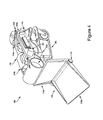
- FIG. 4 illustrates an example robotic device in a fully-folded conformation, according to an example embodiment.
- FIG. 5 illustrates another flow diagram of example operations, according to an example embodiment.
- FIG. 6 illustrates another flow diagram of example operations, according to an example embodiment.
- FIGS. 7A and 7B illustrate a robotic device sweeping objects onto a shovel tool, according to an example embodiment.
- FIG. 8 illustrates another flow diagram of example operations, according to an example embodiment.
- FIG. 9 illustrates a robotic device lifting and moving a chair, according to an example embodiment.
- FIG. 10 illustrates a robotic device lifting and moving a container, according to an example embodiment.
- FIGS. 11A and 11B illustrate a robotic device using a gripper to open a garbage can, according to an example embodiment.
- Example embodiments are described herein.
- the words “example,” “exemplary,” and “illustrative” are used herein to mean “serving as an example, instance, or illustration.” Any embodiment or feature described herein as being an “example,” being “exemplary,” or being “illustrative” is not necessarily to be construed as preferred or advantageous over other embodiments or features.
- the example embodiments described herein are not meant to be limiting.
- the aspects of the present disclosure, as generally described herein and illustrated in the figures can be arranged, substituted, combined, separated, and designed in a wide variety of different configurations, all of which are contemplated herein.
- the example robotic device may include a robotic arm having a limited number of degrees of freedom.
- the limited number of degrees of freedom may reduce a cost of manufacturing and programming the robotic device, making it affordable for non-industrial applications.
- the robotic device may additionally include at least two coordinated end effectors connected at different positions on the robotic arm. Different combinations of end effectors may be chosen to adapt the robotic device to perform different types of coordinated tasks, such as picking up and moving objects of varying sizes.
- the robotic device may comprise a base linkage having a first end and a second end.
- the first end may be connected to a support base.
- the support base may be a stationary anchor point about which or with respect to which the base linkage may rotate.
- the support base may be a mobile support base having wheels, tracks, or legs to allow the robotic device to move about an environment.
- a first end effector may be connected to the second end of the base linkage through a first actuated rotational joint.
- the first end effector may be one of a number of available end effectors.
- the first end effector may be a shovel tool made up of two serially connected portions.
- the robotic device may further include a control arm having a first end and a second end.
- the first end of the control arm may be connected to the second end of the base linkage through a second actuated rotational joint.
- the control arm may be made up of two serially connected linkages.
- the linkages may be serially connected through a third actuated rotational joint.
- a second end effector may be connected to the second end of the control arm through a fourth actuated rotational joint.
- the second end effector may be selected from a number of available end effector.
- the second end effector may include a sweeping tool.
- the sweeping tool may be configured to engage with the shovel tool to move/push/sweep objects onto the shovel tool when actuated by the fourth rotational joint or by the control arm.
- the base linkage may be connected to the support base through an actuated rotational joint configured to rotate the base linkage with respect to the support base.
- the second end effector may additionally or instead include a gripper.
- the gripper may be used by the robotic device to grasp and hold other objects that cannot be moved or grasped using the sweeping tool, the shovel tool, or a combination thereof.
- the gripper may also be used to pick up and move objects by operating in coordination with the shovel tool.
- the gripper may be used to perform a first task while the sweeping tool is performing a second task.
- the gripper may be used to remove a lid from a garbage can and the sweeping tool may be used to sweep garbage off the shovel tool into the garbage can.
- the base linkage may be connected to the support base through a fifth rotational joint.
- the fifth rotational joint may be configured to tilt and/or rotate the base linkage, and thus the entire robotic arm, with respect to the support base.
- the first, second, third, fourth, and fifth joints may all be configured to move in or parallel to the same plane. Consequently, the first and second end effectors as well as the base linkage and control arm may also be configured to move in or parallel to the same plane.
- Limiting the movement to the same or parallel planes may allow the robotic device to minimize an amount of computational power required to coordinate motion of the first end effector and the second end effector. Additionally, limiting the first, second, third, fourth, and/or fifth joints to be one degree of freedom rotational joint may reduce the cost of the robotic device in comparison to a robotic device made with joints having more than one degree of freedom. Additionally, limiting the total number of joints on the robotic device may further reduce the cost of the robotic device. A less expensive robotic device may be more accessible and more popular with non-industrial consumers such as retail consumers who may use the robotic device as a household aid robot.
- first and second end effectors are complementary end effectors (e.g., shovel tool and sweeping tool)
- limiting the movement of the two end effectors to the same or parallel planes may ensure that the two end effectors are always oriented in a preferred orientation with respect to each other.
- the sweeping tool may be oriented such that that when actuated, a long edge of the sweeping tool engages a leading edge of the shovel tool. An example of this orientation is illustrated in FIGS. 2A and 2B .
- the base linkage and the control arm linkages may be offset from each other so as to allow the robotic device to form into a compact conformation, as illustrated in FIGS. 3 and 4 .
- the robotic device may be folded into the compact (fully-folded) conformation in order to minimize an amount of space (“spatial footprint”) occupied by the robotic device when the robotic device is not performing operations and/or is put away for storage.
- spatial footprint an amount of space occupied by the robotic device when the robotic device is not performing operations and/or is put away for storage.
- members of the household may prefer a device that occupies less space when the device is not actively performing useful operations (e.g., the device is charging its batteries or is stowed away for storage).
- folding into a compact form either fully or partially, may allow the robotic device to avoid collisions and/or operate in confined environments.
- the robotic device may be used in a plurality of settings and may be configured to perform operations corresponding to each setting.
- the robotic device may be used as a household aid robot.
- the robotic device may be configured to collect and load laundry into a hamper or washer, clean the floor by collecting garbage, clean up toys by gathering the toys and loading them into a toy storage bin, move pieces of furniture into their proper positions, and fetch drinks, food, and keys, among other possible tasks.
- the robotic device may additionally be used as a yard work aid robot to perform certain yard work such as sweeping up and gathering fallen leaves, sticks, and any other undesirable items that may be left in a back or front yard.
- the robotic device may be configured to perform any of the operations described herein autonomously in order to reduce an amount of human input needed to control the robotic device.
- the design of the robotic device and the robotic arm thereof may be generalized to other tasks and operations.
- the kinematic design of the robotic arm may be adapted to operate in a semiconductor manufacturing process.
- the first end effector may be a forked end effector commonly used by robotic devices in semiconductor manufacturing processes to handle silicon wafers.
- the first actuated rotational joint (connecting the first end effector to the base linkage) may be used to place this first end effector in a first orientation.
- the first orientation may be under or adjacent to the silicon wafer.
- the second actuated rotational joint (connecting the first control arm linkage to the base linkage) may subsequently be actuated to position the control arm in a second orientation. Positioning the control arm in this second orientation may bring the second end effector into proximity of the first end effector.
- the third actuated rotational joint (connecting the second control arm linkage to the first control arm linkage and having the second end effector on the end thereof) may be actuated to position the second end effector to align the second end effector with the first end effector.
- the second end effector may be an end effector adapted to accurately repositioning the silicon wafer on the first end effector.
- the second end effector may be a gripper (e.g., suction gripper) configured to pick up and move the silicon wafer.
- the second end effector may be a photoresist applicator/nozzle or a chemical wash/rinse applicator/nozzle.
- the fourth actuated rotational joint (connecting the second end effector to the second control arm linkage) may be actuated to operate in coordination with the first end effector.
- the branching kinematic structure (first end effector branching from the base linkage, control arm with second end effector connected thereto also branching from the base linkage) and the limited number of degrees of freedom (first end effector and second end effector move only in or parallel to the same plane) may be particularly useful in settings like semiconductor manufacturing that require precise positioning of objects (e.g., silicon wafer) with respect to the manufacturing equipment (e.g., lithographic mask). Since the first and second end effectors both branch from a single linkage (the base linkage) and both end effectors may be mechanically limited to always work in or parallel to the same plane, error in positioning of the end effectors with respect to each other may be eliminated or reduced.
- error may be present in horizontal, lateral, and vertical positioning of the two end effectors with respect to each other.
- lateral positioning error is reduced or eliminated by mechanically confining the end effectors to always move in or parallel to the same plane.
- the robotic arm may be manufactured with low tolerances (manufacture precisely) to ensure that less than a threshold extent of error is present in the relative lateral positioning of the first end effector and the second end effector, thereby improving the precision of operation of the robotic arm.
- Minimizing an extent of lateral positioning error may ensure that the first end effector consistently engages the second end effector in the same position and/or in the same manner (e.g., with the same amount of force).
- the first and second end effectors may be modular. Namely, different end effectors may be installed on the robotic arm of the robotic device depending on the task the robotic device is expected to perform. The end effectors may be changed while the robotic device is performing a process to allow a single robotic device to perform different steps of the process, as opposed to having multiple robotic devices perform the different steps of the process.
- the first end effector may first be a spin plate configured to spin photoresist onto a silicon wafer. The spin plate may subsequently be exchanged for a hot plate to use in the process of baking the silicon wafer. This arrangement of interchangeable end effectors may be useful in small-scale semiconductor manufacturing settings that want the benefit of an automated manufacturing process without the cost of a full robotic processing line.
- the kinematic structure of the robotic arm may be outfitted with different pairs of end effectors to operate in a number of different environments.
- the robotic device may be adapted to sweep up small objects from around the house, the backyard, and/or the sidewalk.
- the robotic device may be adapted to mop the floor of a house.
- the robotic device may also be used as a digger/excavator.
- the first end effector may be an excavator shovel tool and the second end effector may be an excavator bucket tool.
- the robotic device may move the excavator bucket tool in a sweeping motion to push dirt into the excavator shovel tool.
- Other combinations of complementary end effectors may be possible.
- FIG. 1 illustrates an example configuration of a robotic system that may be used in connection with the embodiments described herein.
- the robotic system 100 may be configured to operate autonomously, semi-autonomously, and/or using directions provided by user(s).
- the robotic system 100 may be implemented in various forms, such as a walking robot (e.g., biped, quadruped, hexapod, octoped), a wheeled robot, a stair climbing robot, a robot on tracks, or some other arrangement.
- the robotic system 100 may also be referred to as a robot, robotic device, or mobile robot, among other designations.
- the robotic system 100 may include processor(s) 102 , data storage 104 , and controller(s) 108 , which together may be part of a control system 118 .
- the robotic system 100 may also include sensor(s) 112 , power source(s) 114 , mechanical components 110 , electrical components 116 , and communication link(s) 120 . Nonetheless, the robotic system 100 is shown for illustrative purposes, and may include more or fewer components.
- the various components of robotic system 100 may be connected in any manner, including wired or wireless connections. Further, in some examples, components of the robotic system 100 may be distributed among multiple physical entities rather than a single physical entity. Other example illustrations of robotic system 100 may exist as well.
- Processor(s) 102 may operate as one or more general-purpose hardware processors or special purpose hardware processors (e.g., digital signal processors, application specific integrated circuits, etc.).
- the processor(s) 102 may be configured to execute computer-readable program instructions 106 , and manipulate data 107 , both of which are stored in the data storage 104 .
- the processor(s) 102 may also directly or indirectly interact with other components of the robotic system 100 , such as sensor(s) 112 , power source(s) 114 , mechanical components 110 , electrical components 116 , and/or communication link(s) 120 .
- the data storage 104 may be one or more types of hardware memory.
- the data storage 104 may include or take the form of one or more computer-readable storage media that can be read or accessed by processor(s) 102 .
- the one or more computer-readable storage media can include volatile and/or non-volatile storage components, such as optical, magnetic, organic, or another type of memory or storage, which can be integrated in whole or in part with processor(s) 102 .
- the data storage 104 can be a single physical device.
- the data storage 104 can be implemented using two or more physical devices, which may communicate with one another via wired or wireless communication.
- the data storage 104 may include the computer-readable program instructions 106 and the data 107 .
- the data 107 may be any type of data, such as configuration data, sensor data, and/or diagnostic data, among other possibilities.
- the controller 108 may include one or more electrical circuits, units of digital logic, computer chips, and/or microprocessors that are configured to (perhaps among other tasks) interface between any combination of the mechanical components 110 , the sensor(s) 112 , the power source(s) 114 , the electrical components 116 , the control system 118 , the communication link(s) 120 , and/or a user of the robotic system 100 .
- the controller 108 may be a purpose-built embedded device for performing specific operations with one or more subsystems of the robotic device 100 .
- the control system 118 may monitor and physically change the operating conditions of the robotic system 100 . In doing so, the control system 118 may serve as a link between portions of the robotic system 100 , such as between mechanical components 110 and/or electrical components 116 . In some instances, the control system 118 may serve as an interface between the robotic system 100 and another computing device. Further, the control system 118 may serve as an interface between the robotic system 100 and a user. For instance, the control system 118 may include various components for communicating with the robotic system 100 , including a joystick, buttons, and/or ports, etc. The example interfaces and communications noted above may be implemented via a wired or wireless connection, or both. The control system 118 may perform other operations for the robotic system 100 as well.
- control system 118 of robotic system 100 may also include communication link(s) 120 configured to send and/or receive information.
- the communication link(s) 120 may transmit data indicating the state of the various components of the robotic system 100 .
- information read by sensor(s) 112 may be transmitted via the communication link(s) 120 to a separate device.
- Other diagnostic information indicating the integrity or health of the power source(s) 114 , mechanical components 110 , electrical components 116 , processor(s) 102 , data storage 104 , and/or controller 108 may be transmitted via the communication link(s) 120 to an external communication device.
- the robotic system 100 may receive information at the communication link(s) 120 that is then processed by the processor(s) 102 .
- the received information may indicate data that is accessible by the processor(s) 102 during execution of the program instructions 106 . Further, the received information may change aspects of the controller(s) 108 that may affect the behavior of the mechanical components 114 or the electrical components 116 .
- the received information may indicate a query requesting a particular piece of information (e.g. the operational state of one or more of the components of the robotic system 100 ). The processor(s) 102 may subsequently transmit the particular piece of information back out the communication link(s) 120 .
- the communication link(s) 120 may include a wired connection.
- the robotic system 100 may include one or more ports to interface the communication link(s) 120 to an external device.
- the communication link(s) 120 may include, in addition to or alternatively to the wired connection, a wireless connection.
- Some example wireless connections may utilize a cellular connection, such as CDMA, EVDO, GSM/GPRS, or 4G telecommunication, such as WiMAX or LTE.
- the wireless connection may utilize a Wi-Fi connection to transmit data to a wireless local area network (WLAN).
- WLAN wireless local area network
- the wireless connection may also communicate over an infrared link, Bluetooth, or a near-field communication (NFC) device.
- NFC near-field communication
- control system 118 may communicate with other systems of the robotic system 100 via wired or wireless connections, and may further be configured to communicate with one or more users of the robot.
- control system 118 may receive an input (e.g., from a user or from another robot) indicating an instruction to perform a particular set of household tasks such as cleaning up the floor.
- the input to control system 118 may be received via the communication link(s) 120 .
- control system 118 may perform operations to cause the robotic device 100 to use sensors 112 to analyze the floor of the house and subsequently use mechanical components 110 to gather and remove any dirt, clothes, toys, and/or other obstacles from the floor.
- a control system may receive an input indicating an instruction to gather dirty clothes, towels, and/or bedding and place them in the washer.
- the control system 118 (perhaps with the assistance of other components or systems) may search the house for clothes, towels, bedding, and/or other housewares that appear to require washing.
- the control system 118 may determine a speed and/or gait for the robotic system 100 based on the environment/layout of the house and may also alter or adjust the route or path or portions thereof as the robotic system 100 scans and analyzes the contents of each room of the house.
- Operations of the control system 118 may be carried out by the processor(s) 102 . Alternatively, these operations may be carried out by the controller 108 , or a combination of the processor(s) 102 and the controller 108 . In some embodiments, the control system 118 may partially or wholly reside on a device other than the robotic system 100 , and therefore may at least in part control the robotic system 100 remotely. Communication link(s) 120 may be used at least in part to carry out the remote communication.
- Mechanical components 110 represent hardware of the robotic system 100 that may enable the robotic system 100 to perform physical operations.
- the robotic system 100 may include physical members such as leg(s), arm(s), wheel(s), linkage(s), track(s), and/or end effector(s).
- the physical members or other parts of robotic system 100 may further include motors and actuators arranged to move the physical members in relation to one another.
- the robotic system 100 may also include one or more structured bodies for housing the control system 118 and/or other components, and may further include other types of mechanical components.
- the particular mechanical components 110 used in a given robot may vary based on the design of the robot, and may also be based on the operations and/or tasks the robot may be configured to perform.
- the mechanical components 110 may include one or more removable components.
- the robotic system 100 may be configured to add and/or remove such removable components, which may involve assistance from a user and/or another robot.
- the robotic system 100 may be configured with removable arm(s), hand(s), fee(t), leg(s), linkage(s), wheel(s), track(s), and/or end effector(s) so that these members can be replaced or changed as needed or desired.
- the robotic system 100 may include one or more removable and/or replaceable battery units or sensors. Other types of removable components may be included within some embodiments.
- the robotic system 100 may include sensor(s) 112 arranged to sense aspects of the robotic system 100 .
- the sensor(s) 112 may include one or more force sensors, torque sensors, velocity sensors, acceleration sensors, position sensors, proximity sensors, motion sensors, location sensors, load sensors, temperature sensors, touch sensors, depth sensors, ultrasonic range sensors, infrared sensors, object sensors, and/or cameras, among other possibilities.
- the robotic system 100 may be configured to receive sensor data from sensors that are physically separated from the robot (e.g., sensors that are positioned on other robots or located within the environment in which the robot is operating).
- the sensor(s) 112 may provide sensor data to the processor(s) 102 (perhaps by way of data 107 ) to allow for interaction of the robotic system 100 with its environment, as well as monitoring of the operation of the robotic system 100 .
- the sensor data may be used in evaluation of various factors for activation, movement, and deactivation of mechanical components 110 and electrical components 116 by control system 118 .
- the sensor(s) 112 may capture data corresponding to the terrain of the environment, the layout of the environment (e.g., the floor plan of the house, apartment, condominium, business residence, etc.), the surface geometry of the environment (e.g., stairs, inclines, etc.), location of nearby objects, and/or identity of nearby objects, which may assist with environment recognition and navigation.
- sensor(s) 112 may include RADAR (e.g., for long-range object detection, distance determination, and/or speed determination), LIDAR (e.g., for short-range object detection, distance determination, and/or speed determination), SONAR (e.g., for underwater object detection, distance determination, and/or speed determination), VICON® (e.g., for motion capture), one or more cameras (e.g., stereoscopic cameras for 3D vision), a global positioning system (GPS) transceiver, and/or other sensors for capturing information of the environment in which the robotic system 100 is operating.
- the sensor(s) 112 may monitor the environment in real time, and detect obstacles, elements of the terrain, weather conditions, temperature, and/or other aspects of the environment.
- the robotic system 100 may include sensor(s) 112 configured to receive information indicative of the state of the robotic system 100 , including sensor(s) 112 that may monitor the state of the various components of the robotic system 100 .
- the sensor(s) 112 may measure activity of systems of the robotic system 100 and receive information based on the operation of the various features of the robotic system 100 , such the operation of extendable legs, arms, wheels, linkages, actuators, and/or other mechanical and/or electrical features of the robotic system 100 .
- the data provided by the sensor(s) 112 may enable the control system 118 to determine errors in operation as well as monitor overall operation of components of the robotic system 100 .
- the robotic system 100 may use force sensors to measure load on various components of the robotic system 100 .
- the robotic system 100 may include one or more force sensors on one or more robotic members such as a arms, legs, wheels, linkages, and/or end effectors to measure the load on the actuators that move the one or more members.
- the robotic system 100 may use one or more position sensors to sense the position of the actuators of the robotic system. For instance, such position sensors may sense states of extension, retraction, and/or rotation of the actuators on arms or legs.
- the sensor(s) 112 may include one or more velocity and/or acceleration sensors.
- the sensor(s) 112 may measure both linear and angular velocity and/or acceleration.
- the sensor(s) 112 may include an inertial measurement unit (IMU) having a 3-axis accelerometer, a 3-axis gyroscope, and a 3-axis magnetometer.
- IMU inertial measurement unit
- the IMU may sense velocity and acceleration in the world frame, with respect to the gravity vector.
- the velocity and acceleration sensed by the IMU may then be translated to that of the robotic system 100 based on the location of the IMU in the robotic system 100 and the kinematics of the robotic system 100 .
- the robotic system 100 may include other types of sensors not explicated discussed herein. Additionally or alternatively, the robotic system may use particular sensors for purposes not enumerated herein.
- the robotic system 100 may also include one or more power source(s) 114 configured to supply power to various components of the robotic system 100 .
- the robotic system 100 may include a hydraulic system, electrical system, batteries, and/or other types of power systems.
- the robotic system 100 may include one or more batteries configured to provide charge to components of the robotic system 100 .
- Some of the mechanical components 110 and/or electrical components 116 may each connect to a different power source, may be powered by the same power source, or be powered by multiple power sources.
- the robotic system 100 may include a hydraulic system configured to provide power to the mechanical components 110 using fluid power. Components of the robotic system 100 may operate based on hydraulic fluid being transmitted throughout the hydraulic system to various hydraulic motors and hydraulic cylinders, for example.
- the hydraulic system may transfer hydraulic power by way of pressurized hydraulic fluid through tubes, flexible hoses, or other links between components of the robotic system 100 .
- the power source(s) 114 may charge using various types of charging, such as wired connections to an outside power source, wireless charging, combustion, or other examples.
- the electrical components 116 may include various mechanisms capable of processing, transferring, and/or providing electrical charge or electric signals.
- the electrical components 116 may include electrical wires, circuitry, and/or wireless communication transmitters and receivers to enable operations of the robotic system 100 .
- the electrical components 116 may interwork with the mechanical components 110 to enable the robotic system 100 to perform various operations.
- the electrical components 116 may be configured to provide power from the power source(s) 114 to the various mechanical components 110 , for example.
- the robotic system 100 may include electric motors. Other examples of electrical components 116 may exist as well.
- the robotic system 100 may include a body, which may connect to or house appendages and components of the robotic system.
- the structure of the body may vary within examples and may further depend on particular operations that a given robot may have been designed to perform. For example, a robot developed to carry heavy loads may have a wide body that enables placement of the load. Similarly, a robot designed to reach high speeds may have a narrow, small body that does not have substantial weight.
- the body and/or the other components may be developed using various types of materials, such as metals or plastics.
- a robot may have a body with a different structure or made of various types of materials.
- the body and/or the other components may include or carry the sensor(s) 112 . These sensors may be positioned in various locations on the robotic device 100 , such as on the body and/or on one or more of the appendages, among other examples.
- the robotic device 100 may carry a load, such as a type of cargo that is to be transported.
- the load may also represent external batteries or other types of power sources (e.g., solar panels) that the robotic device 100 may utilize. Carrying the load represents one example use for which the robotic device 100 may be configured, but the robotic device 100 may be configured to perform other operations as well.
- the robotic system 100 may include various types of legs, arms, wheels, tracks, treads, linkages, and so on.
- the robotic system 100 may be configured with zero or more legs.
- An implementation of the robotic system with zero legs may include wheels, tracks, treads, or some other form of locomotion.
- An implementation of the robotic system with two legs may be referred to as a biped or bipedal robot, and an implementation with four legs may be referred as a quadruped or quadrupedal robot. Implementations with six or eight legs are also possible.
- the robotic device may be used, for example, as a household help robot to carry out various tasks around a person's home (e.g., house, apartment, condominium, or any other type of residence).
- the robotic device may be programmed to clean the floors of the house, collect and load dirty laundry into a clothes hamper or washing machine, throw away garbage scattered around the home, organize/return various household items to their respective storage places, and/or fetch various items (e.g., glass of water, keys) for a member of the household.
- the example robotic device described herein may be constructed with a reduced number of degrees of freedom in order to reduce the cost of manufacturing and programming the robotic device.
- FIGS. 2A and 2B illustrate an example robotic device 200 .
- Robotic device 200 may be used to carry out the operations described herein.
- a robotic arm of robotic device 200 may be mounted on or connected to a base 202 .
- the base 202 may be a mobile base configured to move about an environment using different means of movement including, for example, wheels, tracks, legs, and/or any combinations or variations thereof.
- the base 202 may have located thereon a control system 204 of the robotic device 200 .
- the control system 204 may be the example control system 118 shown and described with respect to FIG. 1 .
- the mobile base may also have located thereon a subset of the sensors 112 , electrical components 116 , and/or power sources 114 , as shown and described with respect to FIG. 1 .
- the robotic arm may include a base linkage 210 .
- a first end 210 a of base linkage 210 may be connected to the mobile base 202 through joints 206 and 208 .
- the base linkage may be a mechanical interconnection including at least one mechanical rod, bar, or shaft.
- the mechanical rod may be a single, straight (linear) rod.
- the mechanical rod may have geometric features (e.g., bends, twists) therein.
- the base linkage may be a multi-bar/rod linkage (e.g., four-bar linkage) configured to move the first end effector and the control arm with respect to the support base in at least one direction (with at least one degree of freedom).
- Joint 206 may be an actuated rotational joint configured to rotate/swivel the base linkage 210 horizontally, from side to side (yaw rotation about the z-axis of coordinate system 234 ) with respect to the base 202 .
- joint 206 may be a purely rotational joint allowing the base linkage 210 to move only in or parallel to a plane of rotation of the joint 206 (base linkage 210 may be restricted to yaw rotation about actuated rotational joint 206 ).
- Joint 208 may be an actuated rotational joint configured to rotate/tilt base linkage 210 vertically, up and down (pitch rotation about the x-axis of coordinate system 234 ) with respect to the base 202 .
- joint 208 may be a purely rotational joint allowing the base linkage 210 to move only in or parallel to a plane of rotation of the joint 208 (base linkage 210 may be restricted to pitch rotation about actuated rotational joint 208 ).
- the principal rotations of yaw, pitch, and roll are illustrated by example coordinate system/reference frame 234 , shown in FIGS. 2A and 2B .
- the coordinate system 234 may be attached to the robotic device or a portion thereof such as, for example, the base 202 of the robotic device.
- the principle rotations may be defined with respect to the robotic device (in a robot-centered reference frame), as opposed to being defined with respect to a reference frame external to the robot (e.g., a reference frame fixed at a point on the Earth).
- a first end effector 218 may be attached to a second end 210 b of the base linkage 210 .
- the first end effector 218 may be a shovel tool comprising a first portion 218 a connected to the second end 210 b of base linkage 210 and a second portion 218 b serially connected to the first portion 218 a .
- a shovel tool may be an implement including a broad blade, a scoop, a pan, and/or a tray that may be used for digging, lifting, carrying, and/or moving materials/objects.
- the shovel tool may be rounded, flat, or have different geometric features included therein.
- the specific design of the shovel tool may vary between embodiments. The specific design (e.g., shape of the shovel tool and geometric features thereof) may be based on an intended use of the shovel tool in a particular embodiment.
- the first portion 218 a may be rigidly connected (in a fixed orientation) to the second end 210 b of the base linkage 210 .
- a pitch of the shovel tool 218 may be controlled by controlling the pitch of the base linkage 210 using actuated rotational joint 208 .
- the second portion 218 b of the shovel tool 218 may be rotatably connected to the first shovel tool portion 218 a through rotational joint 216 .
- Rotational joint 216 may be an actuated rotational joint configured to move the second shovel tool portion 218 b with respect to the first shovel tool portion 218 a .
- Joint 216 may be actuated by actuator/motor 214 .
- Motor 214 may be coupled to the rotational joint 216 through a drive belt (not shown).
- the shovel tool 218 may be movable, about joint 216 , between a closed conformation, illustrated in FIG. 2A , and an open conformation, illustrated in FIG. 2B , as well as other conformations therebetween.
- the robotic arm may further include a control arm comprising first linkage 220 and second linkage 224 , connected to the second end 210 b of the base linkage 210 .
- a first end of the first linkage 220 may be connected to the second end 210 b of the base linkage 210 through rotational joint 212 .
- a first end of the second linkage 224 may be connected to a second end of the first linkage 220 through rotational joint 222 .
- Rotational joint 212 may be actuated to control a pitch of the first linkage 220 as well as the pitch of the control arm (first linkage 220 and second linkage 224 ) as a whole.
- Rotational joint 222 may be actuated to control a pitch of the second linkage 224 .
- the rotational joints 212 and 222 may be purely rotational joints configured to rotate the first linkage 220 and the second linkage 224 , respectively, in or parallel to a single plane of rotation.
- the control arm may also be referred to as an actuated control arm when it is actuated and/or configured to be actuated by at least one joint.
- the robotic arm may additionally include a second end effector 230 .
- Second end effector 230 may be connected to the second end of the second control arm linkage 224 through joint 226 .
- Joint 226 may be an actuated rotational joint configured to rotate/actuate the second end effector 230 in a plane parallel to or coincident with the plane of rotation of joints 212 and 222 .
- the second end effector 230 may be controlled directly by rotation of joint 226 or indirectly by movements of the control arm (first control arm linkage 220 and second control arm linkage 224 ) and/or movements of base linkage 210 .
- FIG. 2 illustrates second end effector 230 comprising a sweeping tool 228 and a gripper 232 .
- a sweeping tool may be an implement including at least one flexible member that may be used for sweeping, moving, pushing, or otherwise actuating materials and/or objects.
- the sweeping tool may be a brush-like or broom-like implement including a plurality of flexible members (e.g., bristles) bound together and configured to be used to sweep, move, push, or otherwise actuate a material or object to move the material or object onto the shovel tool.
- the sweeping tool 228 may be mounted to the actuated rotational joint 226 at a first point on the joint 226 .
- the gripper tool 232 may be mounted to the actuated rotational joint 226 at a second point on the joint 226 .
- the sweeping tool 228 and/or the gripper 232 may be configured to engage with the shovel tool 218 .
- the sweeping tool 228 may comprise a plurality of compliant finger-like elements (e.g., bristles) arranged in at least one row and oriented parallel to a leading edge of the shovel tool 218 (e.g., the leftmost edge of the second shovel tool portion 218 b , as shown in FIG. 2B ).
- the bristles of the sweeping tool 228 may be configured to brush over the leading edge of the shovel tool 218 when the sweeping tool 228 is moved by the control arm and/or joint 226 .
- the sweeping tool 228 may comprise a squeegee rubber oriented parallel to the leading edge of the shovel tool 218 .
- the bristles may be held in place by (the bristles may projected from) a rigid (e.g., metallic) frame 228 a .
- the rigid frame may serve to attach the bristles to the rotational joint 226 .
- the gripper 232 may be a conventional pinch gripper having one set of opposing digits. In addition to being configured to rotate about joint 226 (pitch rotation), the gripper 232 may be configured to rotate in at least one additional degree of freedom (e.g., roll rotation). In an example embodiment, when the gripper 232 is additionally configured for roll rotation, the gripper 232 can be rotated about the roll axis to adapt the gripper 232 to handle objects with of various shapes and/or having different geometric features. For example, in one orientation, the gripper 232 can be used to grasp a glass of water by the sides, by pinching the glass between the at least two fingers of the gripper 232 .
- the gripper 232 can subsequently be caused to rotate by 90 degrees and used to grasp a stack of papers by placing one finger underneath the stack and pushing on a top surface of the stack with the second finger.
- the number of degrees of freedom of the gripper 232 and/or similar end effectors may be based on a desired cost of the robotic device 200 and/or a desired set of functions that the robotic device 200 is expected to perform.
- the second end effector 230 may comprise more than two different end effectors, each useful for a particular task that the robotic device is expected to perform. Each of the different end effectors may be rotated in and out of an operational position using the actuated rotational joint 226 .
- the base 202 may be a mobile base configured to move about an environment.
- the mobile base 202 may be configured to move using at least one of a plurality of different means of movement including, for example, wheels (as shown in FIGS. 2A and 2B ), tracks, legs, and/or any combinations or variations thereof.
- the means of movement of mobile base 202 may be chosen based on an expected operating environment of robotic device 200 . For example, when working inside a house with level floors and no large obstacles, robotic device 200 may utilize a wheeled base to move about.
- the robot may utilize tracks or legs (e.g., a quadrupedal, hexapedal, or octopedal base).
- the mobile base 202 may be outfitted with a specialized mechanism and/or arrangement of legs that allows the robotic device 200 to climb up and down stairs.
- the mobile base 202 may be modularized to allow the means of movement of the mobile base 202 to be adapted to the terrain the robot encounters or the environment the robot is expected to work in.
- the mobile base 202 may be designed to swap between wheels, tracks, legs, and/or other specialized locomotive mechanisms.
- the process of swapping the means of movement of a mobile base may be carried out by a docking station configured to detach a first (presently attached) means of movement (e.g., wheels) and attach a second means of movement (e.g., caterpillar tracks).
- the robotic device 200 may be designed to swap between different mobile bases having different means of movement.
- the process of swapping between different mobile bases having different means of movement may be accomplished by a docking station configured to detach the robotic device 200 from a first base having a first means of movement (e.g., wheels) and attach a second mobile base having a second means of movement (e.g., caterpillar tracks).
- a docking station configured to detach the robotic device 200 from a first base having a first means of movement (e.g., wheels) and attach a second mobile base having a second means of movement (e.g., caterpillar tracks).
- the support base 202 may be another robotic device such as bipedal or quadrupedal robotic device.
- the robotic device 200 may be attached on top of a quadrupedal robot designed to carry loads.
- the robotic device 200 may be utilized to load and unload objects onto the quadrupedal robot.
- the base 202 may be a fixed/stationary anchor/attachment point.
- Robotic device 200 may be confined to operate in a particular radius of the fixed anchor point.
- robotic device 200 may operate in a shipping warehouse to pick up, move, and/or sort packages.
- the support base 202 may carry thereon additional end effectors including alternative versions of gripper 232 , sweeping tool 228 , and shovel tool 218 .
- the additional end effectors may further include different gripper attachments such as alternative versions of the gripping fingers of gripper 232 .
- Support base 202 may further house thereon a docking station configured to allow robotic device to swap between different end effectors.
- the base linkage 210 may be a telescopic linkage configured to increase a length of the base linkage 210 by extending the telescopic linkage.
- the telescopic linkage may be actuated hydraulically, pneumatically, or by a motor.
- the telescopic linkage may increase the reach of the robotic device 200 , allowing the robotic device 200 to, for example, reach objects located in higher places than would normally be possible without a telescopic linkage.
- base linkage may be a mechanical interconnection including at least one mechanical rod, bar, or shaft configured to move the control arm and the first end effector with respect to the support base.
- the base linkage may be a straight rod/shaft 210 , as illustrated in FIGS. 2A and 2B .
- the base linkage may be a four-bar linkage including four pivotably connected joints.
- the four-bar linkage may be driven by at least one actuator (e.g., motor) to rotate with respect to the support base.
- the rotation with respect to the support base may be a pitch rotation, as illustrated in FIGS. 2A and 2B .
- joints 206 and 208 may be located along different points of the base linkage 210 without affecting the overall functionality of the robotic device described herein.
- base linkage 210 may include additional actuated rotational joints.
- an additional rotational joint configured to produce a pitch rotation may be included in the middle of base linkage 210 .
- Other designs may be possible.
- a first end effector 218 may be attached to a second end 210 b of the base linkage 210 .
- the first end effector 218 may be at least one of a plurality of available end effectors including pinch grippers, suction grippers, forks/pitchforks, fork/pitchfork-like end effectors, shovels, shovel-like end effectors, excavator buckets, sweeping tools, pans, and specialized end effectors such as a centrifugal spin plate used in spin-coating a thin film onto a semiconductor substrate.
- the first end effector 218 may be modular, allowing different types of end effectors to be attached depending on the particular task performed by the robotic device 200 .
- the first end effector 218 may be a shovel tool comprising a first portion 218 a connected to the second end 210 b of base linkage 210 and a second portion 218 b serially connected to the first portion 218 a .
- the first portion 218 a may be rigidly connected (in a fixed orientation) to the second end 210 b of the base linkage 210 .
- a pitch of the shovel tool 218 may be controlled by controlling the pitch of the base linkage 210 using actuated rotational joint 208 .
- the first portion 218 a may be connected to the second end 210 b of the base linkage 210 through an actuated rotational joint (not shown) coaxial with joint 212 .
- the orientation of the first portion 218 a of the shovel tool 218 may be adjustable in relation to the base linkage 210 .
- the joint connecting the first portion 218 a of the shovel tool 218 to the base linkage 210 may be actuated in order to control a pitch of the first shovel tool portion 218 a and therefore also control the pitch of the entire shovel tool 218 .
- the pitch of the shovel tool 218 may be controlled by controlling the pitch of the base linkage 210 using actuated rotational joint 208 . Consequently, the pitch of the shovel tool can be controlled in multiple ways when the first shovel tool portion 218 a is rotatably connected to the second end 210 b of base linkage 210 .
- Rotational joint 216 may be an actuated rotational joint configured to move the second shovel tool portion 218 b with respect to the first shovel tool portion 218 a .
- the actuated joint 216 may be a purely rotational joint configured to rotate the second shovel tool portion in or parallel to the plane of rotation of the actuated joint 216 .
- the plane of rotation of the joint 216 may be parallel to the plane of rotation of the rotational joint connecting the first shovel tool portion 218 a to the base linkage 210 .
- the two planes of rotation may be coincident (same plane of rotation).
- the actuated joint 216 may be used to control a pitch of the second shovel tool portion 218 b . Additionally, since the second shovel tool portion 218 b is attached to the first shovel tool portion 218 a , the pitch of the second shovel tool portion 218 b may also be controlled by controlling the pitch of the first shovel tool portion 218 a , the pitch of the base linkage 210 , or a combination thereof. Alternatively, the second portion 218 b of the shovel tool 218 may be rigidly connected (in a fixed orientation) to the first shovel tool portion 218 a . Thus, a pitch of the second shovel tool portion 218 b might only be controllable by controlling the pitch of the first shovel tool portion 218 a , the pitch of the base linkage 210 , or a combination thereof.
- a leading edge of the shovel tool 218 may include a compliant lip (e.g., rubber lip).
- the compliant lip of the shovel tool may allow the robotic device to operate on delicate surfaces (e.g., scoop/shovel small toys or other small objects off delicate furniture and/or easily scratched flooring) without risk of damaging the surfaces.
- the compliant material additionally reduces the need for precise control of the shovel tool 218 when scooping/loading objects onto shovel tool 218 .
- the compliant material may conform to changes in a height of a surface from which the shovel tool 218 is picking/scooping up objects.
- the compliant lip of shovel tool 218 may further allow for smooth interactions between the shovel tool 218 and the sweeping tool 228 (e.g., the compliant lip may conform to the sweeping tool and “absorb” any error in the relative positioning of the shovel tool 218 and the sweeping tool 228 during operation).
- the compliant material may be, for example, rubber, plastic, or another type of flexible polymeric material.
- the leading edge of the shovel tool 218 may include one or more rollers to allow the shovel tool 218 to roll/glide over surfaces as opposed to scraping and/or dragging along the surfaces.
- the rollers may be spherical, cylindrical, conical, or a combination thereof.
- the rollers may facilitate the process of loading objects onto shovel tool 218 by allowing the objects to roll over the rollers and onto the shovel tool 218 .
- the rollers may reduce an amount of force required to push objects onto the shovel tool 218 .
- the rollers may reduce an amount of friction that has to be overcome in order to push the objects onto the shovel tool 218 .
- the robotic device may be capable of moving heavier objects onto the shovel tool 218 when the leading edge of the shovel tool 218 includes the rollers.
- a second end effector 230 may be attached to the second end of the second control arm linkage 224 .
- the second end effector 230 may be at least one of a plurality of available end effectors including pinch grippers, suction grippers, forks/pitchforks, fork/pitchfork-like end effectors, shovels, shovel-like end effectors, excavator buckets, sweeping tools, pans, and specialized end effectors such as a thin film applicator/nozzle used to deposit a thin film onto a semiconductor substrate.
- the second end effector 230 just like the first end effector 218 , may be modular, allowing different types of end effectors to be attached depending on the particular task performed by the robotic device 200 .
- the second end effector 230 may be connected to the control arm through rotational joint 226 .
- Second end effector may be moved/actuated directly by rotating joint 226 , indirectly by moving the control arm and/or the base linkage 210 , or a combination thereof.
- joint 226 may be a rigid connection between end effector 230 and the second control arm linkage 224 and, in this case, the second end effector 230 may be moved/actuated only indirectly via movement of the control arm (first control arm linkage 220 and second control arm linkage 224 ) and the base linkage 210 .
- second end effector 230 may include more than one end effector.
- second end effector 230 may include sweeping tool 228 and a gripper 232 .
- the sweeping tool 228 may be mounted to the actuated rotational joint 226 at a first point on the joint 226 .
- the gripper tool 232 may be mounted to the actuated rotational joint 226 at a second point on the joint 226 .
- the first point and the second point may be approximately opposite to each other. In some embodiments, the first point and the second point may be separated by, for example, 30, 45, or 60 degrees.
- the degree of separation between the sweeping tool 228 and the gripper 232 may be chosen to allow interchangeable, alternating, and/or coordinated use of the sweeping tool 226 and the gripper 232 .
- Alternating use may comprise, for example, moving the sweeping tool 228 into an operational position wherein the sweeping tool can be used to engage the shovel tool 218 and/or sweep an object onto the shovel tool 218 , as illustrated in FIGS. 7A and 7B .
- the actuated rotational joint 226 may rotate, causing the sweeping tool 228 to move out of the operational position and the gripper 232 to move into the operational position, as illustrated in FIGS. 11A and 11B .
- the gripper While in the operational position, the gripper may be used to operate on the object or another object and/or perform other tasks that the gripper 232 is better adapted for than the sweeping tool 228 .
- the choice of the degree of separation between the attachment point of the sweeping tool 228 (the first point on the joint 226 ) and the attachment point of the gripper (the second point on the joint 226 ) may be driven by at least two considerations. Namely, the degree of separation may be influenced by a speed of alternating the end effectors and an amount of interference between the two end effectors. A small degree of separation such as 30 or 45 degrees may be used to decrease an amount of time it takes to move the end effectors 228 and 230 in and out of the operational position.
- a large degree of separation such as 90 degrees may be chosen to decrease an amount of interference between the gripper 232 and the environment and/or the object being operated on by the sweeping tool 228 while the sweeping tool 228 operates on the object, and vice versa.
- the degree of separation between the sweeping tool 228 and the gripper 232 may be dynamically changed by having the sweeping tool 228 and the gripper 232 attached to different rotational joints (e.g., different coaxial rotational joints, not shown).
- the degree of separation may affect the ability of the robotic device 200 to fold into a compact, fully-folded conformation, as illustrated in FIGS. 3 and 4 .
- the degree of separation may additionally affect the spatial footprint of the fully-folded conformation.
- the sweeping tool 228 may comprise a plurality of compliant finger-like elements (e.g., bristles) arranged in at least one row and oriented parallel to a leading edge of the shovel tool 218 (e.g., the leftmost edge of the second shovel tool portion 218 b , as shown in FIG. 2B ).
- the sweeping tool 228 may comprise a squeegee rubber oriented parallel to the leading edge of the shovel tool 218 .
- the compliant material of the sweeping tool may allow the robotic device to operate on delicate surfaces (e.g., sweep small toys or other small objects off delicate furniture and/or easily scratched flooring) without risk of damaging the surfaces.
- the compliant material additionally reduces the need for precise control of the sweeping action of the sweeping tool 228 .
- the compliant material may conform to changes in height as the sweeping tool 228 moves from a surface of the environment onto the shovel tool 218 . Thus, small errors in positioning of the sweeping tool 228 may be accounted for by the compliance of the sweeping tool 228 .
- the compliant material may be, for example, rubber, plastic, or another type of flexible polymeric material.
- the bristles may be held in place by (the bristles may projected from) a rigid (e.g., metallic) frame 228 a , as illustrated in FIG. 2B .
- the rigid frame may serve to attach the bristles to the rotational joint 226 .
- the rigid frame may also be used in moving, lifting, and manipulating objects.
- the robotic device 200 may use the rigid frame to pin/push an object against the shovel tool 218 or a portion thereof in order to grasp and subsequently lift the object (see FIG. 9 ).
- the object may be large enough or heavy enough such that the compliant bristles alone would bend or deform if the robot 200 attempted to use the bristles to pin the object against the shovel tool 218 , thus preventing the robot 200 from successfully lifting and/or moving the object.
- the gripper 232 may be a conventional pinch gripper having one set of opposing digits. In some embodiments, the gripper may be a three finger gripper, a four finger gripper, a five finger gripper designed to mimic the biomechanics of a human hand, and/or a suction gripper.
- the gripper 232 may be used to, for example, lift the lid off of a garbage can so that the robotic device may empty the contents of the shovel tool 218 into the garbage can (see FIGS. 11A and 11B ).
- the gripper 232 may additionally be used to load objects onto the shovel tool 218 , open doors, and move obstacles as the robotic device 200 is performing various household tasks in a house or apartment.
- the gripper 232 may be configured to rotate in at least one additional degree of freedom (e.g., roll rotation).
- the gripper 232 when the gripper 232 is additionally configured for roll rotation, the gripper 232 can be rotated about the roll axis to adapt the gripper 232 to handle objects with of various shapes and/or having different geometric features.
- the gripper 232 in one orientation, can be used to grasp a glass of water by the sides, by pinching the glass between the at least two fingers of the gripper 232 .
- the gripper 232 can subsequently be caused to rotate by 90 degrees and be used to grasp a stack of papers by placing one finger underneath the stack and pushing on a top surface of the stack with the second finger.
- the number of degrees of freedom of the gripper 232 and/or similar end effectors may be based on a desired cost of the robotic device 200 and/or a desired set of functions that the robotic device 200 is expected to perform.
- the first end effector 218 and the second end effector 230 may be modularized to allow the end effectors to be exchanged or swapped for different end effectors.
- the end effectors 218 and 230 may be swapped based on a task the robotic device 200 is expected or programmed to perform. For example, two-fingered gripper 232 may be swapped for a three-fingered gripper when the robotic device 200 is planned to pick up round objects that would be difficult to grasp with a two-fingered gripper.
- shovel tool 218 may be swapped for a basket/container having a volume larger than a volume of the shovel tool 218 when the robotic device 200 is planned to move a plurality of objects over long distances.
- the end effectors 218 and 230 may be swapped for any number of different end effectors including suction grippers, forks/pitchforks, fork/pitchfork-like end effectors, rakes, scoops, shovels, shovel-like end effectors, excavator buckets, sweeping tools, pans, and other specialized end effectors.
- the process of swapping the end effectors 218 and 230 may be carried out by a docking station configured to detach a first (presently attached) end effector (e.g., pinch gripper) and attach a second end effector (e.g., suction).
- the docking station may be housed on the support base 202 .
- the docking station may be external to robotic device 200 .
- Robotic device 200 may be outfitted with specialized mechanisms that facilitate the process of attaching and detaching different end effectors.
- a standardized mechanical interface may be used across the plurality of different available end effectors to simplify the process of swapping between different end effectors.
- the joints 208 , 212 , 216 , 222 , and 226 may each be configured to rotate in or parallel to a particular plane.
- the joints 208 , 212 , 216 , 222 , and 226 may all be actuated rotational joints configured to move/rotate their respective linkages and end effectors in or parallel to the particular plane. Limiting each of the joints 208 , 212 , 216 , 222 , and 226 to always operate in or parallel to the same plane may allow the second end effector 230 to line up directly with the first end effector 218 (e.g., the sweeping tool 228 is configured to line up and engage with the shovel tool 218 ).
- the specific plane in which the base linkage 210 is allowed to move vertically, up and down (pitch rotation) with respect to the base 202 may change.
- the base linkage 210 is rotated horizontally, from side to side (yaw rotation)
- the first end effector 218 , the control arm (linkages 220 and 224 ), and the second end effector 230 will move with the base linkage 210 due to the mechanical interconnections of the respective components.
- any yaw rotation of the base linkage 210 translates directly into an equal amount of yaw rotation for all other components attached to the base linkage. Consequently, even though the specific plane of rotation may change, the base linkage 210 , the first end effector 218 , the control arm, and the second end effector 230 will continue to be confined to all move in or parallel to the same plane.
- This limited range of motion of the joints 208 , 212 , 216 , 222 , and 226 allows for the control system and control algorithms of the robotic device 200 to be simpler than those of, for example, a six-axis robot.
- the branching structure of the first end effector, the control arm, and the second end effector may improve the consistency of alignment between the first and second end effectors.
- the limited number of degrees of freedom may reduce the cost of producing the robotic device 200 by reducing mechanical complexity and control software/hardware complexity. The reduced cost makes robotic device 200 more affordable for use as an aid in household tasks/chores (e.g., cleaning the house, doing laundry, throwing out the garbage) as well as certain commercial and/or industrial settings.
- the joints 206 , 208 , 212 , 216 , 222 , and 226 may be actuated by an electric motor mounted within and/or adjacent to the joints.
- the motor may be connected and may drive the respective joint and linkage through a gearbox.
- the each of the joints and respective linkages may be driven by a harmonic drive system mounted within each joint. Mounting the drive mechanism inside the joint may decrease the amount of parts protruding from the robotic device 200 , preventing the robot from snagging on furniture, curtains, and other household items as the robot moves around a home (reduces the likelihood of protruding parts hooking/colliding with another robot in a commercial or industrial setting).
- the joints and linkages of the robotic device may be driven/actuated by hydraulic and/or pneumatic pistons and/or actuators.
- the hydraulic or pneumatic actuators may be mounted across the respective joints to exert a moment about the joints.
- Each of the joints 206 , 208 , 212 , 216 , 222 , and 226 as well as any other joints that may be present on the example robotic device 200 may have mechanical, electrical, and/or software-maintained joint limits.
- the range of motion of each joint may be limited by a mechanical hard stop that physically prevents the joint from rotating past certain limits.
- electrical or software joint limits may be enforced by, for example, cutting power to the motor/actuator when a sensor (e.g., joint encoder) senses that a joint has exceeded a preset threshold.
- the joint limits may be set to prevent parts of the robotic device 200 from colliding with each other or otherwise damaging the robot.
- joints 212 , 222 , and 226 may have safety limits that prevent the control arm from causing the gripper 232 to collide with the shovel tool 218 .
- joints 206 and 208 may be limited from moving the base linkage 210 to positions that would cause the robotic device 200 to tip over.
- the joint limit of a first joint may be dynamically changed based on the position of at least one other joint of the robotic system 200 .
- the gripper tool 232 is larger/longer than the sweeping tool 228
- the amount of clearance between the shovel tool 218 and the sweeping tool 228 may be larger than the amount of clearance between the shovel tool 218 and the gripper 232 .
- the joints 212 and 222 may have more conservative joint limits (e.g., smaller allowable range of motion) than when the sweeping tool 228 is in the operational position.
- the robotic device 200 may determine that a rotation of the joint 226 would cause the sweeping tool 228 and/or the gripper 232 to collide with the shovel tool 218 based on the position of the second control arm linkage 224 .
- a joint limit may be set for joint 226 to prevent the joint 226 from rotating the sweeping tool 228 and/or the gripper 232 into a position that would cause the sweeping tool 228 and/or the gripper 232 to collide with the shovel tool.
- the joints and linkages of the robotic device 200 may be interconnected in a way that allows robotic device 200 to fold into a compact form as illustrated in FIGS. 3 and 4 .
- FIG. 3 illustrates the robotic device 200 in a half-folded conformation
- FIG. 4 illustrates the robotic device 200 in a fully-folded conformation.
- the robotic device 200 may have a height that is about 25% of a fully unfolded, maximum height of the robotic device 200 .
- a maximum height of the robotic device 200 may be, for example, 56 inches (142 centimeters). Folding into a compact form may reduce a “spatial footprint” of the robotic device 200 .
- the spatial footprint may be defined as, for example, an amount of volume contained in a three-dimensional (3D) convex hull of the robotic device 200 .
- a smaller spatial footprint may make the robotic device 200 easier and/or more convenient to store.
- the robotic device 200 may require a first extent of space (e.g., the volume of a 3D convex hull of the robotic device 200 in the conformation shown in FIG. 2A ) to store (e.g., store the device in a closet, garage, pantry, warehouse, etc.).
- the robotic device 200 may require a second extent of space to store, where the second extent is smaller than the first extent.
- the robotic device 200 may require a third extent of space to store, where the third extent is smaller than the first extent and the second extent.
- the robotic device 200 may occupy the same amount of “true volume” (e.g., actual volume of the parts making up the robotic device 200 ) regardless of the orientation/positioning of the parts making up robotic device 200 , the spatial footprint may be decreased as the robotic device 200 folds into a half-folded conformation and a fully-folded conformation.
- the robotic device 200 may be designed and/or built to fold into the compact forms (half-folded and fully-folded conformations) illustrated in FIGS. 3 and 4 due at least in part to the following features.
- the base linkage 210 may have a length such that when the base linkage 210 rests on top of the base 202 (the base linkage is “folded down,” positioned tangentially to the base 202 ), the first end effector 218 (e.g., shovel tool 218 ) may be positioned in front of the mobile base 202 (as opposed to resting on top of the mobile base), as illustrated in FIGS. 3 and 4 .
- the first end effector 218 e.g., shovel tool 218
- base linkage 210 has a length such that base linkage 210 is not long enough for the first end effector 218 to be positioned in front of the mobile base 202 , the first end effector 218 may rest on top of the mobile base, preventing the base linkage 210 (and thus the control arm) from entering the fully-folded conformation.
- the first end effector 218 may be configured to fold into a compact form and/or may be positioned in a specific position/orientation.
- the second portion 218 b of the shovel tool 218 may be positioned adjacent and approximately parallel to the first portion 218 a of the shovel tool 218 , as illustrated in FIG. 4 .
- the first portion 218 a of the shovel tool 218 may be oriented perpendicular to a surface the robotic device 200 is resting/operating on, as illustrated in FIGS. 3 and 4 .
- folding into a compact form may comprise moving the first end effector into a specific position/orientation based on a shape and size of the first end effector.
- the spatial footprint of the robotic device 200 may be lower when the first end effector is in the specific position/orientation compared to another position/orientation.
- the first control arm linkage 220 may be horizontally (in the x-direction) offset from the base linkage 210 in a direction perpendicular to the plane of rotation of the first control arm linkage 220 (the plane of rotation of the rotational joint 212 ).
- the first control arm linkage 220 may be offset by a first distance. The first distance may be such that the first control arm linkage 220 may be positioned approximately parallel (e.g., within 5 degrees of parallel) to the base linkage 210 .
- the second end 220 b of the first control arm linkage 220 may be positioned adjacent to the first end 210 a of the base linkage 210 (where the first end 220 a of the first control arm linkage 220 is connected to the second end 210 b of the base linkage 210 ).
- the second control arm linkage 224 may be horizontally (in the x-direction) offset from the base linkage 210 in a direction perpendicular to the plane of rotation of the second control arm linkage 224 and/or the plane of rotation of the first control arm linkage 220 (the plane of rotation of the rotational joint 222 and/or the plane of rotation of the rotational joint 212 , respectively).
- the second control arm linkage 224 may be offset by a second distance. The second distance may be such that the second control arm linkage 224 may be positioned approximately parallel (e.g., within 5 degrees of parallel) to the base linkage 210 .
- the second end 224 b of the second control arm linkage 224 may be positioned adjacent to the second end 210 b of the base linkage 210 and adjacent to the first end 220 a of the second control arm linkage 220 (where the first end 224 a of the first control arm linkage 224 is connected to the second end 220 b of the first control arm linkage 210 ).
- the first distance (horizontal offset between first control arm linkage 220 and base linkage 210 ) and the second distance (horizontal offset between second control arm linkage 224 and base linkage 210 ) may be equal.
- the second control arm linkage 224 may be configured to, in the folded conformation, rest on top of the first control arm linkage 220 (as illustrated in FIG. 4 ) or underneath the first control arm linkage 220 (not shown). In other embodiments, the second distance may be different from the first distance.
- the second control arm linkage 224 may be configured to, in the folded conformation, rest adjacent to the first control arm linkage 220 .
- control arm first control arm linkage 220 and second control arm linkage 224
- control arm linkages 220 and 224 may be rigidly connected at joint 222 .
- the angle between the first control arm portion 220 and the second control arm portion 224 may be fixed at, for example, 30, 45, or 60 degrees, among other possible angles.
- folding into a compact form may comprise positioning the second end 224 b of the second control arm portion 224 (second end of the control arm) adjacent to the second end 210 b of the base linkage 210 .
- Folding into a compact form may additionally comprise positioning at least one of the first control arm portion 220 and the second control arm portion 224 approximately parallel (e.g., within 5 degrees of parallel) to the base linkage 210 .
- the second end effector 230 may be configured to fold into a compact form and/or may be positioned in a specific position/orientation.
- the gripper 232 may be positioned adjacent and approximately parallel to the second control arm portion 224 , as illustrated in FIG. 4 .
- the gripper 232 may be rotated into a particular conformation by rotating about any of the axes the gripper 232 is configured to rotate about (e.g., pitch axis, roll axis, yaw axis).
- the sweeper tool 228 may be positioned adjacent and approximately parallel to the second control arm portion 224 .
- folding into a compact form may comprise moving the second end effector into a specific position/orientation based on a shape and size of the second end effector.
- the spatial footprint of the robotic device 200 may be lower when the second end effector is in the specific position/orientation compared to another position/orientation.
- robotic device 200 illustrated in FIGS. 2A and 2B , and any portions thereof may be controlled by a control system to perform various operations, some of which are described herein by way of example.
- the robotic device 200 and/or the control system thereof may be programmed to perform the operations autonomously and/or under the control of an operator.
- the robotic device 200 may be used as a household aid robot.
- Robotic device 200 may be programmed or controlled by a human user to carry out functions such as, for example, cleaning the house by collecting objects from a floor of the house, loading a clothes washer or clothes hamper with dirty laundry by collecting dirty clothes, linens, and/or towels from around the house, fetching the mail from a mailbox, tidying up the house by placing furniture such as chairs in their proper/desired positions, and/or taking the garbage to the curb on garbage pickup day.
- functions such as, for example, cleaning the house by collecting objects from a floor of the house, loading a clothes washer or clothes hamper with dirty laundry by collecting dirty clothes, linens, and/or towels from around the house, fetching the mail from a mailbox, tidying up the house by placing furniture such as chairs in their proper/desired positions, and/or taking the garbage to the curb on garbage pickup day.
- Other tasks and operations not explicitly described herein may also be possible.
- the example robotic device 200 may be programmed or commanded to perform the tasks using a number of programming means including, but not limited to, a graphical user interface (GUI), voice command, and/or by labeling various objects around the house with barcodes (e.g., one-dimensional and/or two-dimensional barcodes), where the barcodes, when scanned by the robotic device 200 , cause the robot to perform a specific operation on the labeled objects.
- GUI graphical user interface
- the example robotic device 200 may be given specific commands and/or instructions such as a command to take a specific object to a specific location (e.g., “take the blue shirt to the laundry hamper” or “fetch the car keys from the living room”).
- the example robotic device may be given general commands and/or instructions such as a general command to clean up the house (e.g., “load the laundry hamper with dirty laundry” or “find my car keys”).
- the robotic device 200 may utilize various machine learning algorithms in order to determine a sequence of steps to carry out the desired functions and operations. Machine learning algorithms may also be utilized to optimize the sequence of operations in order to reduce a length of time it takes the robotic device to carry out a particular command, function, operation, or task. For example, the robotic device 200 may learn where to search for dirty clothes by determining where members of the household are most likely to leave dirty clothes based on where, in the past, members of the household have left dirty clothes.
- the commands and/or instructions given to the robotic device 200 by a user may comprise or be deconstructed into a number of sub-commands or lower level operations that the robotic device 200 may take in order to perform the desired operation.
- loading the laundry hamper with dirty laundry may comprise instructions that cause the robotic device 200 to use mobile base 202 to navigate the house/apartment while using sensors mounted on the robotic device 200 to scan the house for objects that may fall within the category of “dirty laundry.”
- the robotic device 200 may perform a more detailed analysis of the object in order to determine whether the shirt is clean or dirty.
- the robotic device 200 may use the first end effector 218 and/or the second end effector 230 to move the shirt in order to spread the shirt out on the floor. While the shirt is spread out on the floor, the robotic device 200 may perform additional scans of the shirt in order to determine whether the shirt has any stains.
- the robotic device 200 may be programmed to distinguish between design features of the shirt (e.g., a design that looks like it might be a stain) and true stains (e.g., food splattered on the shirt) by, for example, referencing an image of the shirt against a database of images of shirts (e.g., a database of images of the articles of clothing of members of the household).
- design features of the shirt e.g., a design that looks like it might be a stain
- true stains e.g., food splattered on the shirt
- the robotic device 200 may additionally flip the shirt to look for stains on the other side of the shirt.
- the robotic device 200 may pick up the shirt using at least one of the first end effector 218 and the second end effector 230 .
- the mobile base 202 of the robotic device may move the robotic device 200 to the laundry hamper (the drop-off location).
- the robotic device 200 may use at least one of the first end effector 218 and the second end effector 230 to place the shirt in the hamper.
- the high-level tasks (e.g., load the washer with dirty laundry) performed by the robotic device 200 and/or the robotic arm thereof may be broken down into general operations that the robotic device 200 and/or the robotic arm thereof perform in order to accomplish the tasks.
- the general operations may be low-level operations/commands that make up more complex tasks.
- An example of a complex task may be grasping and moving an object.
- An example of a low-level operation may be actuating joint 226 for a specific period of time to rotate the end effector from a first orientation to a second orientation. Multiple low-level operations may be combined to cause robotic device 200 to carry out various complex tasks.
- FIG. 5 illustrates a flow diagram 500 of operations that the robotic arm or example robotic device, as shown in FIGS. 2A and 2B , may perform.
- a first rotational joint may be actuated to rotate a first end effector of a robotic device to a first orientation.
- the first end effector may be connected to a second end of a base linkage through the first rotational joint.
- the first rotational joint may be configured to rotate the first end effector in a first plane.
- the first end effector may be, for example, shovel tool 218 , as illustrated in FIGS. 2A and 2B .
- the first end effector may be positioned in the first orientation in order to, for example, pick up an object or have an object placed thereon.
- a second rotational joint may be actuated to rotate a control arm of a robotic device to a second orientation.
- a first end of a first linkage of the control arm may be connected to the second end of the base linkage through the second rotational joint.
- the second rotational joint may be configured to rotate the control arm in or parallel to the first plane.
- the first linkage of the control arm may be linkage 220 of robotic device 200 . Actuating the second rotational joint (e.g., joint 212 ) may move the entire control arm.
- a third rotational joint may be actuated to align a second end effector with the first end effector based on the first orientation and the second orientation.
- the second end effector may be connected to a second end of a second linkage of the control arm.
- a first end of the second linkage may be connected to a second end of the first linkage through the third actuated rotational joint.
- the third actuated rotational joint may be configured to rotate the second linkage in or parallel to the first plane. Actuating the third rotational joint (e.g., joint 222 ) may align the second end effector (e.g., sweeping tool 228 ) with the first end effector because the second end effector may be attached to the second end of the second linkage.
- a fourth rotational joint may be actuated to operate the second end effector in coordination with the first end effector.
- the second end effector may be connected to the second end of the second linkage through the fourth rotational joint.
- the fourth rotational joint may be configured to rotate the second end effector in or parallel to the first plane.
- Actuation of the third rotational joint may be based on the first orientation (the orientation of the first end effector) because, in order to align the second end effector with the first end effector, the robotic device may use data indicating the position/orientation of the first end effector in determining a position to which the second end effector must be moved to align with the first end effector.
- data indicating the position/orientation of the first end effector may be used in determining a path along which to move the second end effector in order to align the second end effector with the first end effector.
- Actuation of the third joint may also be based on the second orientation (the orientation of the control arm). Rotation of the second rotational joint may change the position/orientation of the first linkage. However, since the second linkage is connected to the first linkage, rotation of the second joint may also change the position of the second linkage. Further, since the second end effector is connected to the second end of the second linkage, rotation of the second joint may additionally affect the position of the second end effector.
- the second orientation may provide information about a current position of the second end effector, allowing actuation of the third joint to take into account the current position of the second end effector in aligning the second end effector with the first end effector.
- the robotic device may consider the position and/or orientation of any joints or linkages that have an effect on the relative position/orientation of the first end effector and the second end effector.
- the robotic device may simultaneously (in parallel) coordinate the rotation of the first, second, and third joints in order to coordinate operations of the first end effector and the second end effector.
- the second orientation and the rotation of the third rotational joint may be determined in parallel.
- the second orientation may depend on the planned rotation of the third joint, and vice versa.
- Aligning the second end effector with the first end effector may also be referred to as bringing the second end effector into an operational position with respect to the first end effector.
- the operational position may vary and may depend on the particular type of end effectors of the robotic device as well as the task being performed by the robotic device. For example, when the first end effector is shovel tool 218 and the second end effector is sweeping tool 228 , the operational position may comprise placing shovel tool 218 next to a first side of an object and placing the sweeping tool 228 on a side opposite the first side of the object. The sweeping tool 228 may then be moved or actuated by either the control arm or joint 226 to push the object onto the shovel tool.
- a welding robot may have as the first end effector a gripper/holder and as the second end effector a welding electrode holder/handle outfitted with a welding electrode.
- the first end effector may hold and/or position at least two pieces of metal to be welded together. Aligning the second end effector with the first end effector may involve bringing a tip of the electrode to a position/orientation where the welding process will start.
- Operating the second end effector in coordination with the first end effector may include different patterns of motion depending on the specific types of end effectors as well as the particular task being performed by the robotic device. For example, when the robotic device is used as a household aid robot with the first end effector being shovel tool 218 and the second end effector being sweeping tool 228 , operating the second end effector in coordination with the first end effector may involve actuating the fourth rotational joint to rotate the sweeping tool to push an object onto the shovel tool. In the example of the welding robot from above, operating the second end effector in coordination with the first end effector may involve actuating the fourth rotational joint to move the welding electrode along a desired welding path.
- the first end effector when the robotic arm is used in semiconductor manufacturing, the first end effector may be a photoresist spin-coating plate (rotating plate) and the second end effector may be a photoresist applicator or nozzle.
- the first end effector may be positioned in a first orientation to load a silicon wafer onto the spin plate.
- the photoresist applicator may be brought into proximity of the silicon wafer resting on the spin plate and may be centered with the silicon wafer.
- Operating the second end effector in coordination with the first end effector may comprise causing the photoresist applicator/nozzle to begin applying the photoresist when the spin plate reaches a predetermined rotational speed.
- operating the second end effector in coordination with the first end effector may additionally include actuating the first rotational joint, the second rotational joint, and the third rotational joint to move the corresponding linkages to perform a desired task.
- the welding electrode may be consumed.
- the robotic arm may need to continuously bring the second end effector closer to the first end effector in order to maintain contact between the welding electrode and the metal being welded.
- FIGS. 9 and 10 Another example of adjusting multiple joints while the second end effector is operating in coordination with the first end effector is described and illustrated with respect to FIGS. 9 and 10 .
- FIG. 6 illustrates another example flow diagram 600 including operations that may be performed by a robotic device such as example robotic device 200 of FIGS. 2A and 2B .
- an actuated control arm of a robotic device may be caused to move a sweeping tool to push an object onto a shovel tool.
- the shovel tool and a first end of the actuated control arm may each be connected to a second end of a base linkage of the robotic device.
- the sweeping tool may be connected to a second end of the actuated control arm.
- the actuated control arm may be made up of first control arm linkage 220 and second control arm linkage 224 , as shown in FIGS. 2A and 2B .
- the shovel tool may be, for example, shovel tool 218 connected to the second end 210 b of base linkage 210 .
- the sweeping tool may be sweeping tool 228 .
- the base linkage may be caused to raise the actuated control arm and the shovel tool while the object is disposed on the shovel tool by causing an actuated rotational joint to rotate the base linkage with respect to a mobile base of the robotic device.
- the actuated rotational joint may connect a first end of the base linkage to the mobile base.
- the actuated rotational joint may be joint 208 , as shown in FIGS. 2A and 2B .
- the joint 208 may produce a pitch rotation of the base linkage 210 with respect to the base, causing the vertical position of second end 210 b of the base linkage 210 to increase.
- the vertical position of the actuated control arm and the shovel tool 218 may also increase since both are connected to the second end 210 b of the base linkage 210 . Raising the base linkage 210 (increasing a vertical position of the base linkage) may decrease an extent of horizontal area occupied by the robotic device 200 , making it easier to maneuver the robotic device 200 around the environment.
- the mobile base may be caused to navigate to a drop-off location while the object is disposed on the shovel tool.
- the drop-off location may be a storage container (e.g., storage container 702 shown in FIGS. 7A and 7B ) or area of the house specifically designated as storage space for the one or more small toys.
- the robotic device may be programmed with the drop-off location or may autonomously (e.g., via machine learning algorithms) learn that a particular container or location is the drop-off location for a particular class/type of objects (e.g., shoes go on the rack located next to the front door).
- the shovel tool may be caused to drop off the object at the drop-off location.
- joint 216 may be actuated to move the second shovel tool portion 218 b below the horizontal, causing the objects disposed thereon to slide off the shovel tool 218 .
- the control arm may actuate the sweeping tool 228 to sweep the objects disposed on shovel tool 218 off shovel tool 218 .
- tilting the second shovel tool portion 218 b may result in the one or more objects breaking as they are dropped from shovel tool 218 .
- FIGS. 7A and 7B illustrate robotic device 200 performing the operations of block 602 .
- actuated control arm (linkages 220 and 224 ) of example robotic device 200 is shown moving sweeping tool 228 to push object(s) 700 onto the shovel tool 218 .
- the example robotic device 200 may be programmed to collect and organize small objects (e.g., small toys, cereal and/or other food dropped on the floor, etc.).
- Robotic device 200 may, autonomously or in response to commands from a user, search an area of interest (e.g., house, apartment, office, or portion thereof) for objects that match a particular criteria (e.g., scattered toys, dropped food).
- the robotic device may use a mobile base such as mobile base 202 to navigate through the area of interest.
- Robotic device 200 may, based on sensor data received from one or more sensors, find/locate one or more object of interest 700 (e.g., toys, dropped food, dirty laundry). In response to locating the one or more objects of interest 700 , the robotic device may use mobile base 202 to move the robotic device closer to the object(s) of interest 700 . The robotic device may position the shovel tool 218 adjacent to the object(s) of interest 700 , as illustrated in FIG. 7A . The second shovel tool portion 218 b may be placed parallel or approximately parallel to the floor/base of the area of interest. A leading edge 218 c of the shovel tool 218 may be oriented to face the objects 700 .
- object of interest 700 e.g., toys, dropped food, dirty laundry.
- the control arm (linkages 220 and 224 ) and the rotational joint 226 may move the sweeping tool 228 into a pre-sweep position (operational position as shown in FIG. 7A ).
- the pre-sweep position may be such that the object(s) of interest 700 are located between the sweeping tool 228 and shovel tool 218 , as shown in FIG. 7A (e.g., between a long edge of the sweeping tool 228 and the leading edge 218 c of the shovel tool 218 ).
- the control arm may be caused to move the sweeping tool 228 from the pre-sweep position (operational position/orientation shown in FIG.
- object(s) 700 may vary in size. In some embodiments, the objects may be smaller, equal to, or larger in size than shovel tool 218 , as is shown later herein.
- the process of controlling sweeping tool 228 to move objects 700 onto shovel tool 218 may be of low computational complexity due to the shovel tool 218 and the sweeping tool 228 being limited to move in the same plane or in parallel planes. Limiting the movement of the two end effectors ( 218 and 228 ) to the same or parallel planes may ensure that the two end effectors can be reoriented into a preferred orientation for a particular task quickly and with reduced computational path planning overhead. For example, due to the joint structure of robotic device 200 , the long edge of the sweeping tool 228 and the leading edge 218 c of the shovel tool 218 may always be oriented parallel to each other. The parallel orientation may be a preferred orientation for the sweeping tool 228 and shovel tool 218 end effector pair.
- the sweeping tool 218 if the sweeping tool 218 is not moved into the operational position by the control arm and/or rotational joint 226 , the sweeping tool might not engage the at least one of object(s) 700 when moved by the control arm.
- the operational position may vary depending on the type of object being picked up or actuated and the type of end effectors used. In general, the operational position of a particular end effector or set of end effectors may be a position that, when the end effectors are actuated, results in the end effectors successfully operating on (e.g., moving, grasping, picking up, welding) an object of interest.
- the robotic device may determine that the one or more objects may be fragile or that the one or more objects may belong to a class of fragile objects by, for example, referencing the one or more objects against a database of objects that are expected to be encountered by the robot in a particular setting (e.g., house, apartment, office, back yard, warehouse).
- a particular setting e.g., house, apartment, office, back yard, warehouse.
- the robotic device may minimize an amount of time it takes to unload/drop off the one or more objects by tilting the shovel tool 218 , thereby causing the one or more objects to fall off the shovel tool 218 and land at or near the drop-off location.
- the robotic device may minimize a likelihood of damaging the one or more objects as follows.
- the robotic device may cause the base linkage 210 to bring the shovel tool 218 closer to the ground/floor of the environment/drop-off location (lower the shovel tool 218 toward the ground/floor, thereby decreasing a vertical distance between the ground/floor and the shovel tool 218 ).
- the robotic device may cause the control arm (e.g., linkages 220 and 224 ) to move the sweeping tool 228 to push the one or more objects off of the shovel tool 218 and into/onto the drop-off location, thereby reducing the risk of damaging the one or more objects.
- FIG. 8 shows flow diagram 800 that comprises additional or alternative operations that may be performed by a robotic device such as example robotic device 200 shown in FIGS. 2A and 2B .
- a robotic device may be caused to grasp an object between a second end effector and a first end effector by pressing the object against the first end effector using the second end effector.
- the second end effector may be connected to a second end of a control arm.
- the first end effector and a first end of the control arm may each be connected to a second end of a base linkage.
- the first end effector may be shovel tool 218 .
- the second end effector may be sweeping tool 228 and/or gripper 232 .
- the base linkage may be caused to raise the object grasped between the first end effector and the second end effector by causing an actuated rotational joint to rotate the base linkage with respect to a support base.
- the actuated rotational joint may connect a first end of the base linkage to the support base.
- the support base may be a fixed/stationary anchor point about which the robotic device may operate.
- the support base may be mobile base 202 .
- the second end effector and the first end effector may be caused to perform a coordinated lift while moving the object.
- the robotic device may maintain a constant pitch of the first end effector by adjusting the orientation of the first end effector as the base linkage raises the object.
- the robotic device may maintain the second end effector in a constant position in relation to the first end effector by adjusting the orientation of the actuated control arm in response to adjustments in the orientation of the first end effector.
- maintaining the second end effector in a constant position in relation to the first end effector may further include rotating the second actuated rotational joint in response to adjustments in the orientation of the first end effector.
- grasping an object between the first end effector and the second end effector may comprise pushing (pinning) the object against the first end effector by causing the control arm to push the object against the first end effector with the second end effector.
- the robot 200 may be used to pick up a compliant/soft object (e.g., pillow, shirt, linens, stuffed animal, shop rags) by using the sweeping tool 228 to push the complaint object against the shovel tool 218 .
- the sweeping tool 228 may push the object against the first portion 218 a of the shovel tool 218 or against the second portion 218 b of the shovel tool.
- the amount of force applied by the sweeping tool to the object may depend on properties of the object, including, but not limited to, size, shape (geometric features), mass, density, and/or fragility.
- grasping an object may comprise using the first end effector to support the object while using the second end effector to stabilize the object.
- FIG. 9 illustrates robotic device 200 , as illustrated in FIGS. 2A and 2B , lifting chair 900 .
- Robotic device 200 may place shovel tool 218 (second portion 218 b of the shovel tool) underneath the seat of the chair 900 in order to support the weight of the chair 900 .
- the robotic device 200 may also use the second end effector, namely the sweeping tool 228 , to stabilize the chair 900 by pushing the chair 900 , using the sweeping tool 228 , against the first shovel tool portion 218 a , thereby applying forces counteracting any gravitational and/or inertial forces that may cause the chair 900 to slide or fall off the shovel tool 218 .
- the second end effector namely the sweeping tool 228
- FIG. 10 illustrates another example embodiment where a robotic device 200 , as illustrated in FIGS. 2A and 2B , may use a first end effector to support an object while using a second end effector to stabilize the object as the object is being lifted.
- FIG. 10 shows robotic device 200 holding container/box 1000 using the shovel tool 218 and gripper 232 .
- Robotic device 200 may place shovel tool 218 (second portion 218 b of the shovel tool) underneath the bottom of the container/box 1000 in order to support the weight of the container/box 1000 .
- the robotic device 200 may also use the second end effector, namely the gripper 232 , to stabilize the container 1000 by gripping an edge/side of the container 1000 , thereby preventing any gravitational and/or inertial forces from causing the container 1000 to slide or fall off the shovel tool 218 .
- the gripper 232 may additionally be used to push the container 1000 against the first shovel tool portion 218 a as part of the stabilizing operation.
- the robotic device may be programmed to decide how to pick up an object (e.g., sweep the object onto the shovel tool, grasp the object between the first end effector and the second end effector, support the object on the first end effector while stabilizing with the second end effector) based on the properties of the object (e.g., size, shape, mass, density, fragility).
- the robotic device may determine or estimate the properties of the object using one or more sensors mounted on the robotic device and/or in the environment occupied by the robotic device. For example, shape and geometric features may be determined based on data received from a vision sensor (e.g., camera, LIDAR).
- a vision sensor e.g., camera, LIDAR
- Mass may be determined or estimated based on a load measured on the actuators configured to actuate the joints of robotic device 200 (e.g., joints 208 , 212 , 216 , 222 , and 226 ).
- Fragility may be estimated by referencing an image of the object against a database of relevant objects (e.g., common household objects may be considered relevant when the robot is used as a household aid robot).
- robotic device 200 may determine that small objects 700 are small enough to place onto the shovel tool 218 .
- Robotic device 200 may be further determine that sweeping the small objects 700 onto the shovel tool 218 may be faster than individually loading the small objects 700 onto the shovel tool 218 using the gripper 232 .
- the robotic device may use the sweeping tool 228 to push the small objects 700 onto shovel tool 218 .
- robotic device 200 may determine that chair 900 is too large to be fully supported on the shovel tool 218 in a stable manner. Robotic device 200 may further determine that chair 900 does not contain any features that may be securely gripped by gripper 232 . However, robotic device 200 may also determine that chair 900 may be secured in place using the sweeping tool 228 while a portion of chair 900 rests on the sweeping tool 218 (specifically, the second portion 218 b ). Specifically, chair 900 may be secured in place by placing the rigid portion of the sweeping tool 228 underneath the seat on the side opposite to the side that is supported by shovel tool 218 , as shown in FIG. 9 . Thus, robotic device 200 may use the shovel tool 218 and sweeping tool 228 to grasp and move the chair.
- robotic device 200 may be configured to determine that container 1000 is too large to be fully supported on the shovel tool 218 in a stable manner.
- Robotic device 200 may further determine that although the container 1000 may be secured in place using sweeping tool 228 , the sweeping tool 228 may lose grip of the edge of the container 1000 (the sweeping tool 228 may slip over the edge, leaving container 1000 unsecured) as the robotic device 200 experiences disturbances (e.g., a person accidentally bumps into the robotic device 200 , the robotic device 200 drives over uneven terrain) while moving container 1000 .
- Robotic device 200 may further determine that gripper 232 may be used to securely (more securely than sweeping tool 228 ) grasp the side of the container 1000 .
- robotic device 200 may use the shovel tool 218 and the gripper 232 to lift and move the container 1000 .
- Performing a coordinated lift may keep level the object(s) being lifted, thereby preventing the objects from tipping, sliding about, and/or spilling the contents of any container being lifted.
- the robotic device 200 did not perform a coordinated lift but instead only caused the base linkage 210 to tilt upwards about joint 208 (e.g., into approximately the position illustrated in FIG. 2B ), some contents of container 1000 may be spilled out once the robotic arm reaches the position illustrated in FIG. 2B .
- the container 1000 would not be kept level during the uncoordinated lift.
- the container 1000 may eventually be brought into an orientation where the container 1000 may be perpendicular to the orientation shown in FIG. 10 , thus allowing contents of the container 1000 to spill out of the container 1000 .
- a pitch of the container 1000 may be kept constant (e.g., the container may be kept level) by adjusting the position/orientation of the shovel tool 218 is response to movements of the base linkage 210 .
- the shovel tool 218 e.g., the second shovel tool portion 218 b
- the shovel tool 218 may be caused to tilt down (second shovel tool portion 218 b may rotate counterclockwise about joint 216 ).
- the net effect of the clockwise rotation of base linkage 210 about joint 208 and counterclockwise rotation of the second shovel tool portion 218 b about joint 216 may result in a pitch of the second shovel tool portion 218 b remaining constant.
- the pitch of the container 1000 may also remain constant.
- a constant pitch of the shovel tool 218 may be maintained by adjusting the portion/orientation of both the first shovel tool portion 218 a and the second shovel tool portion 218 b.
- the coordinated lift may further comprise maintaining the second end effector (e.g., gripper 232 ) in a constant position in relation to the first end effector (e.g., the shovel tool 218 ).
- the constant position of the gripper 232 may be maintained by adjusting the position/orientation of the control arm in response to movements and adjustments of the orientation/position of the shovel tool 218 .
- the constant position of gripper 232 may additionally be maintained by rotating the gripper about joint 226 in response to movements and adjustments of the orientation/position of the shovel tool 218 .
- the gripper 232 may be maintained in a constant orientation with respect to the shovel tool in order to maintain a firm grip on the edge/side of the container 1000 .
- the shovel tool 218 and the gripper 232 may move in continuous synchrony.
- the operations of blocks 806 A and 806 B may be performed in parallel.
- the position of the gripper 232 may simultaneously be increased by 1 cm in the y-direction.
- the shovel tool 218 may move first, followed by a delay, followed by a corresponding movements of the gripper 232 .
- the delay in movement between the shovel tool 218 and the gripper 232 may result in the gripper 232 losing grip on the edge of container 1000 .
- moving the shovel tool 218 and the gripper 232 with minimum delay (e.g., synchronously) between movement of the shovel tool 218 and the gripper 232 may increase the reliability with which the robotic device 200 picks up, holds, moves, and drops off objects.
- the second end effector 230 may comprise both a sweeping tool 228 and gripper 232 .
- the sweeping tool 228 and the gripper 232 may be used in an alternating manner or in combination to perform a particular task. Interchangeable use of the sweeping tool 228 and the gripper 232 may be accomplished by rotating the sweeping tool and the gripper 232 in and out of an operational position using actuated rotational joint 226 , as previously described.
- FIGS. 11A and 11B illustrate an example embodiment where the sweeping tool 228 and the gripper tool 232 are used in combination.
- robotic device 200 may load onto the shovel tool at least one object by, for example, using the sweeping tool 228 to sweep the at least one object onto the shovel tool 218 .
- FIG. 11A shows objects 1100 loaded onto the shovel tool.
- the objects 1100 may have been loaded onto the shovel tool in a manner similar to that described with respect to objects 700 in FIGS. 6A and 6B .
- Objects 1100 may be, for example, clumps of paper or tissue.
- Robotic device 200 may have found objects 1100 around the house in response to being commanded to clean up the house.
- Robotic device 200 may have determined the objects 1100 to be garbage.
- robotic device 200 may move to a drop-off location.
- the drop off location for objects 1100 determined to be garbage, may be a garbage/trash can 1102 .
- Garbage can 1102 may have thereon a lid 1104 .
- the robotic device 200 may need to remove the lid 1104 of the garbage can.
- the robotic device 200 may cause gripper 232 to move into an operational position.
- the operational position may be a position that allows the gripper 232 to grasp the lid 1104 , as illustrated in FIG. 11A .
- the gripper 232 may be opened and the control arm (linkages 220 and 224 ) along with the base linkage 210 may be moved to lower the gripper 232 onto a rim of the lid 1104 .
- the gripper 232 may subsequently be closed, gripping lid 1104 .
- the control arm and the base linkage 210 may be actuated, causing the lid 1104 held by the gripper 232 to be lifted off the garbage can 1102 .
- the lid 1104 may be removed completely and may be placed on the ground next to the garbage can 1102 .
- the lid 1104 may be connected to the garbage can 1102 by a hinge.
- the hinged lid 1104 may be supported in the open position and prevented from closing using the gripper 232 , the shovel tool 218 , the control arm, the base linkage 210 , or any combination or portion thereof.
- the shovel tool 218 may be moved into a position where a side of the shovel tool 218 supports the hinged lid 1104 in an open position.
- the rotational joint 226 may be caused to rotate, moving gripper 228 out of the operational position and moving sweeping tool 228 into the operational position, as shown in FIG. 11B .
- sweeping tool 228 and shovel tool 218 may be actuated to cause the objects 1100 to be unloaded from the shovel tool 218 and loaded into the garbage can 1102 .
- the shovel tool 218 may be caused to tilt forward, causing the objects 1100 to slide off the shovel tool 218 .
- the sweeping tool 228 may be used to sweep the objects 1100 off the shovel tool 218 .
- Using the sweeping tool 228 to remove the objects may be particular useful when, for example, the shovel tool 218 contains multiple objects intended to be delivered to different locations. For example, one object may need to be dropped off at garbage can 1102 while another object may be, for example, a toy that may need to be dropped off in a toy chest at a different location.
- the complexity of the control system configured to control the robotic device 200 may be reduced when the joints 208 , 212 , 216 , 222 , and/or 226 are configured to rotate in or parallel to the same plane. Rotation in or parallel to the same place results in the corresponding linkages 210 , 220 , and 224 as well as the corresponding end effectors 218 and 228 / 232 also moving in or parallel to the same plane.
- a control system of the robotic device 200 may need to consider fewer degrees of freedom in determining a plan to perform a desired action than, for example, a six axis robotic device.
- the control system may need to consider only the rotational position (pitch) of the sweeping tool 228 with respect to the shovel tool 218 (e.g., rotational position of joint 226 ) and the linear distance between the sweeping tool 228 and the shovel tool 218 .
- the robotic arm may be confined to planar motion, the linear distance and the motion path for traversing the linear distance may be fully expressed in two dimensions (e.g., y-position and z-position).
- a linear distance between the end effectors of two different six axis robotic arms may need to be expressed in three dimensions (e.g., x-position, y-position, and z-position).
- robotic device 200 may be easier to program/control (2D motion planning) than a more complex robotic device (e.g., six axis robot requiring 3D motion planning) and may consequently be more affordable to use as, for example, a household aid robot.
- configuring the joints 208 , 212 , 216 , 222 , and/or 226 to move in or parallel to the same plane may additionally reduce the cost of manufacturing the robotic device 200 .
- Joints having more than one degree of freedom may be more expensive due to their increased mechanical complexity.
- adding a greater number of one degree of freedom joints in order to, for example, allow for redundancy in motion may not increase the per-joint cost but may nonetheless increase the cost of the robotic device due to the added cost of the additional joints.
- a block that represents a processing of information may correspond to circuitry that can be configured to perform the specific logical functions of a herein-described method or technique.
- a block that represents a processing of information may correspond to a module, a segment, or a portion of program code (including related data).
- the program code may include one or more instructions executable by a processor for implementing specific logical functions or actions in the method or technique.
- the program code and/or related data may be stored on any type of computer readable medium such as a storage device including a disk or hard drive or other storage medium.
- the computer readable medium may also include non-transitory computer readable media such as computer-readable media that stores data for short periods of time like register memory, processor cache, and random access memory (RAM).
- the computer readable media may also include non-transitory computer readable media that stores program code and/or data for longer periods of time, such as secondary or persistent long term storage, like read only memory (ROM), optical or magnetic disks, compact-disc read only memory (CD-ROM), for example.
- the computer readable media may also be any other volatile or non-volatile storage systems.
- a computer readable medium may be considered a computer readable storage medium, for example, or a tangible storage device.
- a block that represents one or more information transmissions may correspond to information transmissions between software and/or hardware modules in the same physical device. However, other information transmissions may be between software modules and/or hardware modules in different physical devices.
Landscapes
- Engineering & Computer Science (AREA)
- Robotics (AREA)
- Mechanical Engineering (AREA)
- Aviation & Aerospace Engineering (AREA)
- Radar, Positioning & Navigation (AREA)
- Remote Sensing (AREA)
- Physics & Mathematics (AREA)
- General Physics & Mathematics (AREA)
- Automation & Control Theory (AREA)
- Manipulator (AREA)
Abstract
Description
Claims (20)
Priority Applications (1)
| Application Number | Priority Date | Filing Date | Title |
|---|---|---|---|
| US15/155,368 US9827677B1 (en) | 2016-05-16 | 2016-05-16 | Robotic device with coordinated sweeping tool and shovel tool |
Applications Claiming Priority (1)
| Application Number | Priority Date | Filing Date | Title |
|---|---|---|---|
| US15/155,368 US9827677B1 (en) | 2016-05-16 | 2016-05-16 | Robotic device with coordinated sweeping tool and shovel tool |
Publications (1)
| Publication Number | Publication Date |
|---|---|
| US9827677B1 true US9827677B1 (en) | 2017-11-28 |
Family
ID=60409076
Family Applications (1)
| Application Number | Title | Priority Date | Filing Date |
|---|---|---|---|
| US15/155,368 Expired - Fee Related US9827677B1 (en) | 2016-05-16 | 2016-05-16 | Robotic device with coordinated sweeping tool and shovel tool |
Country Status (1)
| Country | Link |
|---|---|
| US (1) | US9827677B1 (en) |
Cited By (64)
| Publication number | Priority date | Publication date | Assignee | Title |
|---|---|---|---|---|
| US20170364073A1 (en) * | 2016-06-21 | 2017-12-21 | Keith Alan Guy | Modular Robotic System |
| US20180117646A1 (en) * | 2016-10-28 | 2018-05-03 | Fraunhofer-Gesellschaft zur Förderung der angewandten Forschung e.V. | Cleaning Device for Surfaces |
| US10201901B2 (en) * | 2015-01-29 | 2019-02-12 | Canon Kabushiki Kaisha | Robot apparatus, method for controlling robot, program, and recording medium |
| EP3495095A1 (en) * | 2017-12-05 | 2019-06-12 | The Boeing Company | Portable programmable machines, robotic end effectors, and related methods |
| CN109976347A (en) * | 2019-04-11 | 2019-07-05 | 中南大学 | A kind of visual servo paths planning method based on Quick Extended random tree and potential field method |
| CN110014409A (en) * | 2019-04-11 | 2019-07-16 | 齐鲁理工学院 | an industrial manipulator |
| EP3513932A1 (en) * | 2018-01-19 | 2019-07-24 | Raimund Beck Nageltechnik GmbH | Method for producing wall elements from materials which can be nailed and/or clamped |
| CN110074731A (en) * | 2019-04-28 | 2019-08-02 | 哈尔滨工程大学 | A kind of ground sundries cleaning storage robot |
| KR20190106909A (en) * | 2019-06-17 | 2019-09-18 | 엘지전자 주식회사 | Ai moving robot and the control mothod thereof |
| CN110301866A (en) * | 2019-08-01 | 2019-10-08 | 商洛市虎之翼科技有限公司 | Collect the device and its operating method of rubbish |
| US20200165799A1 (en) * | 2017-07-31 | 2020-05-28 | Sumitomo Heavy Industries, Ltd. | Excavator |
| CN111590538A (en) * | 2020-05-26 | 2020-08-28 | 安徽省怀宁县顶雪食品有限公司 | Food packing is with snatching arm |
| WO2020222135A1 (en) * | 2019-04-30 | 2020-11-05 | Universita' Di Pisa | A logistic device |
| CN112192541A (en) * | 2020-10-09 | 2021-01-08 | 常熟云开智能科技有限公司 | Control method for robot to automatically identify scattered workpiece positions and automatically grab |
| EP3762188A2 (en) * | 2018-03-09 | 2021-01-13 | TGW Logistics Group GmbH | Robot system with motion sequences adapted to product types, and operating method therefor |
| CN112568814A (en) * | 2019-09-29 | 2021-03-30 | 北京石头世纪科技股份有限公司 | Automatic cleaning equipment and method for automatically cleaning operation surface |
| WO2021076579A1 (en) * | 2019-10-18 | 2021-04-22 | Off-World, Inc. | Industrial robotic platforms |
| US11013956B2 (en) * | 2016-06-29 | 2021-05-25 | Fundacion Tecnalia Research & Innovatiion | Portable device for upper limb rehabilitation |
| WO2021109943A1 (en) * | 2019-12-04 | 2021-06-10 | 苏州优智达机器人有限公司 | Chassis, self-propelled device and control method |
| EP3834996A1 (en) * | 2019-12-02 | 2021-06-16 | RoyceBot Oy | A control apparatus, a method and a computer program product for a robot |
| US20210229293A1 (en) * | 2018-08-23 | 2021-07-29 | Toyota Research Institute, Inc. | Lifting robot systems |
| WO2021171095A1 (en) * | 2020-02-26 | 2021-09-02 | Greyorange Pte. Ltd. | Method and system and handling deformable objects |
| US11175672B2 (en) * | 2018-05-11 | 2021-11-16 | Toyota Jidosha Kabushiki Kaisha | Autonomous moving system, autonomous moving body, charging dock, control method, and program |
| US11185992B2 (en) * | 2019-02-19 | 2021-11-30 | Hyundai Motor Company | Drive mechanism and service robot having the same |
| US20210370521A1 (en) * | 2019-08-16 | 2021-12-02 | Google Llc | Robotic apparatus for operating on fixed frames |
| US20210386265A1 (en) * | 2020-06-16 | 2021-12-16 | Shenzhen Tecbot Intelligent Robot Co.,Ltd. | Lifting device for a mopping roller of cleaner robot |
| US11219916B2 (en) * | 2017-12-05 | 2022-01-11 | Taikisha Ltd. | Surface treatment system for large object |
| US11235818B2 (en) * | 2018-05-31 | 2022-02-01 | A9.com | Universal anchor points for mobile robots |
| US11247737B2 (en) * | 2018-04-23 | 2022-02-15 | Eagle Technology, Llc | UGV with adaptive stabilizer |
| US11253990B1 (en) * | 2016-10-21 | 2022-02-22 | X Development Llc | Robot control |
| US11254015B2 (en) | 2019-09-24 | 2022-02-22 | Thermo Crs Ltd. | Multi-axis gripper for lab automation robot |
| US11285605B2 (en) * | 2019-02-19 | 2022-03-29 | Material Handling Systems, Inc. | End effector for engaging the flexible packaging materials of parcels |
| WO2022067084A1 (en) * | 2020-09-24 | 2022-03-31 | Grey Orange Pte. Ltd. | Hybrid gripper for handling objects |
| US20220111992A1 (en) * | 2019-02-06 | 2022-04-14 | Marel Salmon A/S | System for opening and emptying a box with a lid |
| WO2022096856A1 (en) * | 2020-11-06 | 2022-05-12 | Dyson Technology Limited | Robotic surface treating system |
| US11389961B2 (en) * | 2017-05-11 | 2022-07-19 | Cloudminds (Shenzhen) Robotics Systems Co., Ltd. | Article searching method and robot thereof |
| US11407118B1 (en) * | 2018-12-10 | 2022-08-09 | Joseph E Augenbraun | Robot for performing dextrous tasks and related methods and systems |
| US20220258330A1 (en) * | 2019-05-13 | 2022-08-18 | Open Mind Ventures, S.L.U. | System for handling elements |
| US11439531B2 (en) * | 2017-05-03 | 2022-09-13 | Danny GOEL | Orthopedic shoulder brace |
| US11446810B1 (en) * | 2017-06-05 | 2022-09-20 | Amazon Technologies, Inc. | Robotic assistant |
| WO2022232447A1 (en) * | 2021-04-28 | 2022-11-03 | Apptronik, Inc | Deployable robotic arm |
| US20220363326A1 (en) * | 2021-05-05 | 2022-11-17 | Khalifa University of Science and Technology | Reconfigurable walking robot |
| US20220371188A1 (en) * | 2021-05-20 | 2022-11-24 | Carnegie Mellon University | Direct Drive End-Effectors with Parallel Kinematics |
| US11559905B2 (en) * | 2020-02-05 | 2023-01-24 | Nauticus Robotics Holdings, Inc. | Subsea manipulator |
| CN115958578A (en) * | 2022-07-12 | 2023-04-14 | 浙江大学 | Movable multi-degree-of-freedom double-arm cooperative robot |
| WO2023072319A1 (en) * | 2021-11-01 | 2023-05-04 | Technicka Univerzita V Liberci | Autonomous mobile platform |
| CN116587291A (en) * | 2023-07-18 | 2023-08-15 | 三一海洋重工有限公司 | Motion control method, device, equipment and engineering machinery |
| CN116709962A (en) * | 2020-11-30 | 2023-09-05 | 克拉特博特股份有限公司 | Debris cleaning robot system |
| EP4269048A1 (en) * | 2022-04-22 | 2023-11-01 | Suntory Holdings Limited | Recovery device and material supplier system |
| US20240081201A1 (en) * | 2022-09-08 | 2024-03-14 | Dina Lindstrom | Leaf Collector Robot Device |
| WO2024010871A3 (en) * | 2022-07-06 | 2024-03-21 | Augenbraun Joseph E | Robot for performing dextrous tasks and related methods and systems |
| US20240141659A1 (en) * | 2022-10-26 | 2024-05-02 | Raise Robotics, Inc. | System and method for automatically mounting brackets within a building site |
| WO2024112386A1 (en) * | 2022-11-22 | 2024-05-30 | Zebra Technologies Corporation | System and method for picking items |
| WO2024140198A1 (en) * | 2022-12-30 | 2024-07-04 | 北京石头世纪科技股份有限公司 | Self-moving cleaning device |
| US12090641B2 (en) * | 2022-12-28 | 2024-09-17 | Guangdong Ocean University | Intelligent garbage sorting robot |
| US12098037B2 (en) | 2018-03-09 | 2024-09-24 | Tgw Logistics Group Gmbh | Picking station and method for automatic picking of goods |
| US12139340B2 (en) | 2018-03-09 | 2024-11-12 | Tgw Logistics Group Gmbh | Robot system for gripping an item in a storage and picking system, and operating method for same |
| US12254443B1 (en) * | 2020-12-04 | 2025-03-18 | Amazon Technologies, Inc. | Robotic item recovery |
| US12397440B1 (en) * | 2018-12-10 | 2025-08-26 | Joseph E. Augenbraun | Robot for performing dextrous tasks and related methods and systems |
| US12427656B2 (en) | 2018-03-09 | 2025-09-30 | Tgw Logistics Gmbh | Robot system for testing a loading space of a loading aid in a storage and order-picking system and operating method therefor |
| WO2026050584A1 (en) * | 2024-08-29 | 2026-03-05 | Clutterbot, Inc. | Scoop for tidying robot |
| WO2026050414A1 (en) * | 2024-08-29 | 2026-03-05 | Clutterbot, Inc. | Cooking and serving general purpose robot |
| WO2026050726A1 (en) * | 2024-08-29 | 2026-03-05 | Clutterbot, Inc. | Dishwasher loading and unloading robot |
| US12617566B2 (en) | 2024-07-15 | 2026-05-05 | Express Scripts Strategic Development, Inc. | Literature packaging system for a high-volume pharmacy |
Citations (60)
| Publication number | Priority date | Publication date | Assignee | Title |
|---|---|---|---|---|
| US1480623A (en) * | 1919-07-07 | 1924-01-15 | August G Liebmann | Automatic fluid-pressure-operated machine shovel |
| USRE23166E (en) * | 1949-11-08 | Loading device for trucks or | ||
| US3148791A (en) * | 1961-12-18 | 1964-09-15 | Hough Co Frank | Tractor loaders |
| US3254781A (en) * | 1961-08-30 | 1966-06-07 | Joy Mfg Co | Self-loading vehicle |
| US3356240A (en) * | 1966-05-31 | 1967-12-05 | Joy Mfg Co | Self-loading vehicle |
| US3369679A (en) * | 1965-11-19 | 1968-02-20 | Morris D. Robinson | Stowable lift apparatus |
| US4283165A (en) * | 1978-09-04 | 1981-08-11 | Commissariat A L'energie Atomique | Motorized manipulator of the cable transmission type having an increased field of action |
| US4865514A (en) | 1986-10-03 | 1989-09-12 | Hitachi, Ltd. | Manipulator system with small arm removably attachable at points along large arm |
| USRE34292E (en) * | 1990-02-16 | 1993-06-22 | Sunbelt Automated Systems, Inc. | Refuse collection and loading system |
| US5807056A (en) * | 1996-09-23 | 1998-09-15 | Qwik-Tip, Inc. | Residential conversion device for a waste collection vehicle |
| US5893794A (en) * | 1996-02-28 | 1999-04-13 | Ebara Corporation | Polishing apparatus having robotic transport apparatus |
| US6203582B1 (en) * | 1996-07-15 | 2001-03-20 | Semitool, Inc. | Modular semiconductor workpiece processing tool |
| US6266901B1 (en) * | 1997-07-11 | 2001-07-31 | Komatsu Ltd. | Work machine |
| US6327517B1 (en) * | 2000-07-27 | 2001-12-04 | Applied Materials, Inc. | Apparatus for on-the-fly center finding and notch aligning for wafer handling robots |
| US6394740B1 (en) * | 1999-06-04 | 2002-05-28 | Distributed Robotics Llc | Material handling device |
| US6656017B2 (en) * | 2001-04-24 | 2003-12-02 | David P. Jackson | Method and apparatus for creating an open cell micro-environment for treating a substrate with an impingement spray |
| US20050095096A1 (en) * | 2003-10-16 | 2005-05-05 | John M. Curotto | Front-loadable refuse container having side-loading robotic arm with motors and other mass mounted at rear of container and use of same with front-loading waste-hauling vehicle having hydraulic front forks or other retractably engageable lift means |
| US20050166413A1 (en) * | 2003-04-28 | 2005-08-04 | Crampton Stephen J. | CMM arm with exoskeleton |
| US20060021408A1 (en) | 2004-07-28 | 2006-02-02 | Hammar Richard H | Hot die cleaning system for quick plastic forming cell |
| US20060212168A1 (en) * | 2003-06-12 | 2006-09-21 | Katsuyuki Baba | Robot remote control system |
| US20060228205A1 (en) * | 2005-03-23 | 2006-10-12 | Syron Engineering & Manufacturing Llc | Adapter assembly including telescoping links |
| US20060242775A1 (en) * | 2005-04-29 | 2006-11-02 | Kwonnie Electrical Products Limited | Electric cleaning sweeper |
| US20060283611A1 (en) * | 2005-06-16 | 2006-12-21 | Wittkowski Donald R | Front-mounted scoop for a vehicle |
| US20070048115A1 (en) * | 2004-12-06 | 2007-03-01 | Nicholas Fenelli | Load carrying vehicle and ejection mechanism and methods related thereto |
| US20070089260A1 (en) * | 2005-10-21 | 2007-04-26 | Tennant Company | Floor cleaning machine debris collection system |
| US20070239315A1 (en) * | 2004-07-13 | 2007-10-11 | Matsushta Electric Industrial Co., Ltd. | Article holding system, robot, and method of controlling robot |
| US7346428B1 (en) | 2002-11-22 | 2008-03-18 | Bissell Homecare, Inc. | Robotic sweeper cleaner with dusting pad |
| WO2009074704A1 (en) | 2007-12-13 | 2009-06-18 | Universidad De Málaga | All-terrain robot system comprising a multiple-articulation manoeuvring arm, and control and sensor elements which are removable while remaining functional |
| US20090170417A1 (en) * | 2005-12-09 | 2009-07-02 | Stork Pmt B.V. | Method and Device for Processing a Carcass Part of Slaughtered Poultry |
| US20100243344A1 (en) * | 2006-09-25 | 2010-09-30 | Board Of Trustees Of Leland Stanford Junior University | Electromechanically counterbalanced humanoid robotic system |
| US20100261411A1 (en) * | 2007-07-12 | 2010-10-14 | Lufthansa Technik Ag | Method and arrangement for maintenance of gas-turbine blades |
| US20100292841A1 (en) * | 2009-05-13 | 2010-11-18 | Wickham Joseph S | Robot with 3d grasping capability |
| US7836811B1 (en) * | 2008-04-17 | 2010-11-23 | Science Applications International Corporation | Tools for use with robotic systems |
| US20110202175A1 (en) * | 2008-04-24 | 2011-08-18 | Nikolai Romanov | Mobile robot for cleaning |
| US20110238205A1 (en) | 2010-02-04 | 2011-09-29 | Georgia Tech Research Corporation | Mobile robot and method for object fetching |
| US20120061155A1 (en) * | 2010-04-09 | 2012-03-15 | Willow Garage, Inc. | Humanoid robotics system and methods |
| US20120152877A1 (en) * | 2010-12-16 | 2012-06-21 | Saied Tadayon | Robot for Solar Farms |
| US8221049B1 (en) * | 2005-09-09 | 2012-07-17 | Westendorf Manufacturing Co., Inc. | Independent hydraulic pinching fingers with detachable secondary implement |
| US20130226341A1 (en) * | 2012-02-27 | 2013-08-29 | Kuka Systems Gmbh | Robot arrangement |
| US20130247829A1 (en) * | 2012-03-12 | 2013-09-26 | Meena A. Taneja | Pet Feeding Robot . Automatic Pet Wet Food Dispenser Robot |
| US20140031977A1 (en) * | 2012-07-27 | 2014-01-30 | Engineering Services Inc. | Modular mobile robot |
| US20140144470A1 (en) * | 2010-05-24 | 2014-05-29 | F.B. Technologies Pty Ltd | System for manipulating objects |
| US8857012B2 (en) | 2007-03-27 | 2014-10-14 | Samsung Electronics Co., Ltd. | Robot cleaner with improved dust collector |
| US20140311271A1 (en) * | 2013-04-23 | 2014-10-23 | Northwestern University | Translational parallel manipulators and methods of operating the same |
| US20140316308A1 (en) * | 2013-04-18 | 2014-10-23 | Daegu Gyeongbuk Institute Of Science And Technology | Upper limb rehabilitation robot for meal assistance or meal rehabilitation training and method thereof |
| US8892253B2 (en) | 2010-12-17 | 2014-11-18 | Korea Institute Of Industrial Technology | Swarm robot and sweeping method using swarm robot |
| US20140360305A1 (en) * | 2013-06-07 | 2014-12-11 | The Johns Hopkins University | Rotation preserving quick connect device |
| US8958911B2 (en) | 2012-02-29 | 2015-02-17 | Irobot Corporation | Mobile robot |
| US20150088300A1 (en) * | 2009-01-19 | 2015-03-26 | Comau, Inc. | Robotic smart end effector tooling |
| US20150104283A1 (en) | 2012-06-19 | 2015-04-16 | Kabushiki Kaisha Yaskawa Denki | Robot system and method for manufacturing processed product |
| US20150226369A1 (en) * | 2014-02-10 | 2015-08-13 | The Boeing Company | Automated Mobile Boom System for Crawling Robots |
| US9230841B2 (en) | 2011-03-11 | 2016-01-05 | Brooks Automation, Inc. | Substrate processing apparatus |
| US20160096653A1 (en) * | 2014-10-01 | 2016-04-07 | United States Postal Service | Transformable tray and tray system for receiving, transporting and unloading items |
| US20160167227A1 (en) * | 2014-12-16 | 2016-06-16 | Amazon Technologies, Inc. | Robotic grasping of items in inventory system |
| US20160199985A1 (en) * | 2015-01-08 | 2016-07-14 | Design & Assembly Concepts, Inc. | System and method for automated affixing of decorative objects to a surface |
| US20160260161A1 (en) * | 2015-03-06 | 2016-09-08 | Wal-Mart Stores, Inc. | Shopping facility assistance systems, devices and methods |
| US20170023947A1 (en) * | 2015-07-26 | 2017-01-26 | John Benjamin Mcmillion | Autonomous cleaning system |
| US20170144309A1 (en) * | 2014-06-13 | 2017-05-25 | Cyberdyne Inc. | Wearing-type movement assistance device |
| US9665095B1 (en) * | 2015-03-19 | 2017-05-30 | Amazon Technologies, Inc. | Systems and methods for removing debris from warehouse floors |
| US9682483B1 (en) * | 2015-03-19 | 2017-06-20 | Amazon Technologies, Inc. | Systems and methods for removing debris from warehouse floors |
-
2016
- 2016-05-16 US US15/155,368 patent/US9827677B1/en not_active Expired - Fee Related
Patent Citations (64)
| Publication number | Priority date | Publication date | Assignee | Title |
|---|---|---|---|---|
| USRE23166E (en) * | 1949-11-08 | Loading device for trucks or | ||
| US1480623A (en) * | 1919-07-07 | 1924-01-15 | August G Liebmann | Automatic fluid-pressure-operated machine shovel |
| US3254781A (en) * | 1961-08-30 | 1966-06-07 | Joy Mfg Co | Self-loading vehicle |
| US3148791A (en) * | 1961-12-18 | 1964-09-15 | Hough Co Frank | Tractor loaders |
| US3369679A (en) * | 1965-11-19 | 1968-02-20 | Morris D. Robinson | Stowable lift apparatus |
| US3356240A (en) * | 1966-05-31 | 1967-12-05 | Joy Mfg Co | Self-loading vehicle |
| US4283165A (en) * | 1978-09-04 | 1981-08-11 | Commissariat A L'energie Atomique | Motorized manipulator of the cable transmission type having an increased field of action |
| US4865514A (en) | 1986-10-03 | 1989-09-12 | Hitachi, Ltd. | Manipulator system with small arm removably attachable at points along large arm |
| USRE34292E (en) * | 1990-02-16 | 1993-06-22 | Sunbelt Automated Systems, Inc. | Refuse collection and loading system |
| US5893794A (en) * | 1996-02-28 | 1999-04-13 | Ebara Corporation | Polishing apparatus having robotic transport apparatus |
| US6203582B1 (en) * | 1996-07-15 | 2001-03-20 | Semitool, Inc. | Modular semiconductor workpiece processing tool |
| US5807056A (en) * | 1996-09-23 | 1998-09-15 | Qwik-Tip, Inc. | Residential conversion device for a waste collection vehicle |
| US6266901B1 (en) * | 1997-07-11 | 2001-07-31 | Komatsu Ltd. | Work machine |
| US6394740B1 (en) * | 1999-06-04 | 2002-05-28 | Distributed Robotics Llc | Material handling device |
| US6327517B1 (en) * | 2000-07-27 | 2001-12-04 | Applied Materials, Inc. | Apparatus for on-the-fly center finding and notch aligning for wafer handling robots |
| US6656017B2 (en) * | 2001-04-24 | 2003-12-02 | David P. Jackson | Method and apparatus for creating an open cell micro-environment for treating a substrate with an impingement spray |
| US7346428B1 (en) | 2002-11-22 | 2008-03-18 | Bissell Homecare, Inc. | Robotic sweeper cleaner with dusting pad |
| US20050166413A1 (en) * | 2003-04-28 | 2005-08-04 | Crampton Stephen J. | CMM arm with exoskeleton |
| US20060212168A1 (en) * | 2003-06-12 | 2006-09-21 | Katsuyuki Baba | Robot remote control system |
| US20050095096A1 (en) * | 2003-10-16 | 2005-05-05 | John M. Curotto | Front-loadable refuse container having side-loading robotic arm with motors and other mass mounted at rear of container and use of same with front-loading waste-hauling vehicle having hydraulic front forks or other retractably engageable lift means |
| US20070239315A1 (en) * | 2004-07-13 | 2007-10-11 | Matsushta Electric Industrial Co., Ltd. | Article holding system, robot, and method of controlling robot |
| US20060021408A1 (en) | 2004-07-28 | 2006-02-02 | Hammar Richard H | Hot die cleaning system for quick plastic forming cell |
| US20070048115A1 (en) * | 2004-12-06 | 2007-03-01 | Nicholas Fenelli | Load carrying vehicle and ejection mechanism and methods related thereto |
| US20060228205A1 (en) * | 2005-03-23 | 2006-10-12 | Syron Engineering & Manufacturing Llc | Adapter assembly including telescoping links |
| US20060242775A1 (en) * | 2005-04-29 | 2006-11-02 | Kwonnie Electrical Products Limited | Electric cleaning sweeper |
| US20060283611A1 (en) * | 2005-06-16 | 2006-12-21 | Wittkowski Donald R | Front-mounted scoop for a vehicle |
| US8221049B1 (en) * | 2005-09-09 | 2012-07-17 | Westendorf Manufacturing Co., Inc. | Independent hydraulic pinching fingers with detachable secondary implement |
| US20070089260A1 (en) * | 2005-10-21 | 2007-04-26 | Tennant Company | Floor cleaning machine debris collection system |
| US20090170417A1 (en) * | 2005-12-09 | 2009-07-02 | Stork Pmt B.V. | Method and Device for Processing a Carcass Part of Slaughtered Poultry |
| US20100243344A1 (en) * | 2006-09-25 | 2010-09-30 | Board Of Trustees Of Leland Stanford Junior University | Electromechanically counterbalanced humanoid robotic system |
| US8857012B2 (en) | 2007-03-27 | 2014-10-14 | Samsung Electronics Co., Ltd. | Robot cleaner with improved dust collector |
| US20100261411A1 (en) * | 2007-07-12 | 2010-10-14 | Lufthansa Technik Ag | Method and arrangement for maintenance of gas-turbine blades |
| WO2009074704A1 (en) | 2007-12-13 | 2009-06-18 | Universidad De Málaga | All-terrain robot system comprising a multiple-articulation manoeuvring arm, and control and sensor elements which are removable while remaining functional |
| US7836811B1 (en) * | 2008-04-17 | 2010-11-23 | Science Applications International Corporation | Tools for use with robotic systems |
| US20110202175A1 (en) * | 2008-04-24 | 2011-08-18 | Nikolai Romanov | Mobile robot for cleaning |
| US20150088300A1 (en) * | 2009-01-19 | 2015-03-26 | Comau, Inc. | Robotic smart end effector tooling |
| US20100292841A1 (en) * | 2009-05-13 | 2010-11-18 | Wickham Joseph S | Robot with 3d grasping capability |
| US20110238205A1 (en) | 2010-02-04 | 2011-09-29 | Georgia Tech Research Corporation | Mobile robot and method for object fetching |
| US20150336264A1 (en) * | 2010-04-09 | 2015-11-26 | Willow Garage, Inc. | Humanoid robotics system and methods |
| US20120061155A1 (en) * | 2010-04-09 | 2012-03-15 | Willow Garage, Inc. | Humanoid robotics system and methods |
| US20140144470A1 (en) * | 2010-05-24 | 2014-05-29 | F.B. Technologies Pty Ltd | System for manipulating objects |
| US20120152877A1 (en) * | 2010-12-16 | 2012-06-21 | Saied Tadayon | Robot for Solar Farms |
| US8892253B2 (en) | 2010-12-17 | 2014-11-18 | Korea Institute Of Industrial Technology | Swarm robot and sweeping method using swarm robot |
| US9230841B2 (en) | 2011-03-11 | 2016-01-05 | Brooks Automation, Inc. | Substrate processing apparatus |
| US20130226341A1 (en) * | 2012-02-27 | 2013-08-29 | Kuka Systems Gmbh | Robot arrangement |
| US8958911B2 (en) | 2012-02-29 | 2015-02-17 | Irobot Corporation | Mobile robot |
| US20130247829A1 (en) * | 2012-03-12 | 2013-09-26 | Meena A. Taneja | Pet Feeding Robot . Automatic Pet Wet Food Dispenser Robot |
| US20150104283A1 (en) | 2012-06-19 | 2015-04-16 | Kabushiki Kaisha Yaskawa Denki | Robot system and method for manufacturing processed product |
| US20140031977A1 (en) * | 2012-07-27 | 2014-01-30 | Engineering Services Inc. | Modular mobile robot |
| US20140316308A1 (en) * | 2013-04-18 | 2014-10-23 | Daegu Gyeongbuk Institute Of Science And Technology | Upper limb rehabilitation robot for meal assistance or meal rehabilitation training and method thereof |
| US9662525B2 (en) * | 2013-04-18 | 2017-05-30 | Daegu Gyeongbuk Institute Of Science And Technology | Upper limb rehabilitation robot for meal assistance or meal rehabilitation training and method thereof |
| US20140311271A1 (en) * | 2013-04-23 | 2014-10-23 | Northwestern University | Translational parallel manipulators and methods of operating the same |
| US20140360305A1 (en) * | 2013-06-07 | 2014-12-11 | The Johns Hopkins University | Rotation preserving quick connect device |
| US20150226369A1 (en) * | 2014-02-10 | 2015-08-13 | The Boeing Company | Automated Mobile Boom System for Crawling Robots |
| US20170144309A1 (en) * | 2014-06-13 | 2017-05-25 | Cyberdyne Inc. | Wearing-type movement assistance device |
| US20160096653A1 (en) * | 2014-10-01 | 2016-04-07 | United States Postal Service | Transformable tray and tray system for receiving, transporting and unloading items |
| US20160167227A1 (en) * | 2014-12-16 | 2016-06-16 | Amazon Technologies, Inc. | Robotic grasping of items in inventory system |
| US20160199985A1 (en) * | 2015-01-08 | 2016-07-14 | Design & Assembly Concepts, Inc. | System and method for automated affixing of decorative objects to a surface |
| US20160260161A1 (en) * | 2015-03-06 | 2016-09-08 | Wal-Mart Stores, Inc. | Shopping facility assistance systems, devices and methods |
| US20170148075A1 (en) * | 2015-03-06 | 2017-05-25 | Wal-Mart Stores, Inc. | Shopping facility assistance systems, devices and methods to detect and handle incorrectly placed items |
| US20170178066A1 (en) * | 2015-03-06 | 2017-06-22 | Wal-Mart Stores, Inc. | Shopping facility discarded item sorting systems, devices and methods |
| US9665095B1 (en) * | 2015-03-19 | 2017-05-30 | Amazon Technologies, Inc. | Systems and methods for removing debris from warehouse floors |
| US9682483B1 (en) * | 2015-03-19 | 2017-06-20 | Amazon Technologies, Inc. | Systems and methods for removing debris from warehouse floors |
| US20170023947A1 (en) * | 2015-07-26 | 2017-01-26 | John Benjamin Mcmillion | Autonomous cleaning system |
Non-Patent Citations (2)
| Title |
|---|
| Mark Prigg, "Google's terrifying two legged giant robot taught how to Clean: Researchers reveal Ian the Atlas robot can now vacuum, sweep and even put the trash away," DailyMail.com, Jan. 16, 2016. |
| Smart End Effectors for Robotic Assembly (Abstract), Assembly Engineering, vol. 30, Issue 8, Aug. 1987. |
Cited By (88)
| Publication number | Priority date | Publication date | Assignee | Title |
|---|---|---|---|---|
| US10201901B2 (en) * | 2015-01-29 | 2019-02-12 | Canon Kabushiki Kaisha | Robot apparatus, method for controlling robot, program, and recording medium |
| US12174642B2 (en) * | 2016-06-21 | 2024-12-24 | Keith Guy | Modular robotic system |
| US20170364073A1 (en) * | 2016-06-21 | 2017-12-21 | Keith Alan Guy | Modular Robotic System |
| US11013956B2 (en) * | 2016-06-29 | 2021-05-25 | Fundacion Tecnalia Research & Innovatiion | Portable device for upper limb rehabilitation |
| US11745332B1 (en) | 2016-10-21 | 2023-09-05 | Google Llc | Robot control |
| US11253990B1 (en) * | 2016-10-21 | 2022-02-22 | X Development Llc | Robot control |
| US20180117646A1 (en) * | 2016-10-28 | 2018-05-03 | Fraunhofer-Gesellschaft zur Förderung der angewandten Forschung e.V. | Cleaning Device for Surfaces |
| US11439531B2 (en) * | 2017-05-03 | 2022-09-13 | Danny GOEL | Orthopedic shoulder brace |
| US11389961B2 (en) * | 2017-05-11 | 2022-07-19 | Cloudminds (Shenzhen) Robotics Systems Co., Ltd. | Article searching method and robot thereof |
| US11446810B1 (en) * | 2017-06-05 | 2022-09-20 | Amazon Technologies, Inc. | Robotic assistant |
| US20200165799A1 (en) * | 2017-07-31 | 2020-05-28 | Sumitomo Heavy Industries, Ltd. | Excavator |
| US12031302B2 (en) * | 2017-07-31 | 2024-07-09 | Sumitomo Heavy Industries, Ltd. | Excavator |
| US10792816B2 (en) | 2017-12-05 | 2020-10-06 | The Boeing Company | Portable programmable machines, robotic end effectors, and related methods |
| US11219916B2 (en) * | 2017-12-05 | 2022-01-11 | Taikisha Ltd. | Surface treatment system for large object |
| EP3495095A1 (en) * | 2017-12-05 | 2019-06-12 | The Boeing Company | Portable programmable machines, robotic end effectors, and related methods |
| EP3513932A1 (en) * | 2018-01-19 | 2019-07-24 | Raimund Beck Nageltechnik GmbH | Method for producing wall elements from materials which can be nailed and/or clamped |
| US12037194B2 (en) | 2018-03-09 | 2024-07-16 | Tgw Logistics Group Gmbh | Robot system with motion sequences adapted to product types, and operating method therefor |
| US12139340B2 (en) | 2018-03-09 | 2024-11-12 | Tgw Logistics Group Gmbh | Robot system for gripping an item in a storage and picking system, and operating method for same |
| US12098037B2 (en) | 2018-03-09 | 2024-09-24 | Tgw Logistics Group Gmbh | Picking station and method for automatic picking of goods |
| US12312172B2 (en) | 2018-03-09 | 2025-05-27 | Tgw Logistics Gmbh | Robot system with motion sequences adapted to product types, and operating method therefor |
| EP3762188A2 (en) * | 2018-03-09 | 2021-01-13 | TGW Logistics Group GmbH | Robot system with motion sequences adapted to product types, and operating method therefor |
| EP3762188B1 (en) * | 2018-03-09 | 2025-12-17 | TGW Logistics GmbH | Robot system with motion sequences adapted to product types, and operating method therefor |
| US12427656B2 (en) | 2018-03-09 | 2025-09-30 | Tgw Logistics Gmbh | Robot system for testing a loading space of a loading aid in a storage and order-picking system and operating method therefor |
| US11247737B2 (en) * | 2018-04-23 | 2022-02-15 | Eagle Technology, Llc | UGV with adaptive stabilizer |
| US11175672B2 (en) * | 2018-05-11 | 2021-11-16 | Toyota Jidosha Kabushiki Kaisha | Autonomous moving system, autonomous moving body, charging dock, control method, and program |
| US11235818B2 (en) * | 2018-05-31 | 2022-02-01 | A9.com | Universal anchor points for mobile robots |
| US12208528B2 (en) * | 2018-08-23 | 2025-01-28 | Toyota Research Institute, Inc. | Lifting robot systems |
| US20210229293A1 (en) * | 2018-08-23 | 2021-07-29 | Toyota Research Institute, Inc. | Lifting robot systems |
| US12397440B1 (en) * | 2018-12-10 | 2025-08-26 | Joseph E. Augenbraun | Robot for performing dextrous tasks and related methods and systems |
| US11407118B1 (en) * | 2018-12-10 | 2022-08-09 | Joseph E Augenbraun | Robot for performing dextrous tasks and related methods and systems |
| US20220111992A1 (en) * | 2019-02-06 | 2022-04-14 | Marel Salmon A/S | System for opening and emptying a box with a lid |
| US12091205B2 (en) * | 2019-02-06 | 2024-09-17 | Marel Salmon A/S | System for opening and emptying a box with a lid |
| US11285605B2 (en) * | 2019-02-19 | 2022-03-29 | Material Handling Systems, Inc. | End effector for engaging the flexible packaging materials of parcels |
| US11185992B2 (en) * | 2019-02-19 | 2021-11-30 | Hyundai Motor Company | Drive mechanism and service robot having the same |
| CN109976347A (en) * | 2019-04-11 | 2019-07-05 | 中南大学 | A kind of visual servo paths planning method based on Quick Extended random tree and potential field method |
| CN109976347B (en) * | 2019-04-11 | 2023-10-13 | 中南大学 | A visual servo path planning method based on rapidly expanding random trees and potential field method |
| CN110014409A (en) * | 2019-04-11 | 2019-07-16 | 齐鲁理工学院 | an industrial manipulator |
| CN110074731A (en) * | 2019-04-28 | 2019-08-02 | 哈尔滨工程大学 | A kind of ground sundries cleaning storage robot |
| WO2020222135A1 (en) * | 2019-04-30 | 2020-11-05 | Universita' Di Pisa | A logistic device |
| US20220203542A1 (en) * | 2019-04-30 | 2022-06-30 | Universita' Di Pisa | A logistic device |
| US11926061B2 (en) * | 2019-04-30 | 2024-03-12 | Universita′ Di Pisa | Logistic device |
| US20220258330A1 (en) * | 2019-05-13 | 2022-08-18 | Open Mind Ventures, S.L.U. | System for handling elements |
| KR20190106909A (en) * | 2019-06-17 | 2019-09-18 | 엘지전자 주식회사 | Ai moving robot and the control mothod thereof |
| US20210323581A1 (en) * | 2019-06-17 | 2021-10-21 | Lg Electronics Inc. | Mobile artificial intelligence robot and method of controlling the same |
| CN110301866A (en) * | 2019-08-01 | 2019-10-08 | 商洛市虎之翼科技有限公司 | Collect the device and its operating method of rubbish |
| CN110301866B (en) * | 2019-08-01 | 2023-07-21 | 商洛市虎之翼科技有限公司 | Device for collecting refuse and method for operating the same |
| US12005571B2 (en) | 2019-08-16 | 2024-06-11 | Google Llc | Robotic apparatus for operating on fixed frames |
| US11745358B2 (en) * | 2019-08-16 | 2023-09-05 | Google Llc | Robotic apparatus for operating on fixed frames |
| US20210370521A1 (en) * | 2019-08-16 | 2021-12-02 | Google Llc | Robotic apparatus for operating on fixed frames |
| US11254015B2 (en) | 2019-09-24 | 2022-02-22 | Thermo Crs Ltd. | Multi-axis gripper for lab automation robot |
| CN112568814A (en) * | 2019-09-29 | 2021-03-30 | 北京石头世纪科技股份有限公司 | Automatic cleaning equipment and method for automatically cleaning operation surface |
| CN112568814B (en) * | 2019-09-29 | 2023-10-27 | 北京石头世纪科技股份有限公司 | Automatic cleaning equipment and method for automatically cleaning operating surface |
| US12005588B2 (en) | 2019-10-18 | 2024-06-11 | Off-World, Inc. | Industrial robotic platforms |
| US11738461B2 (en) | 2019-10-18 | 2023-08-29 | Off-World, Inc. | Systems and methods for industrial robotics |
| WO2021076579A1 (en) * | 2019-10-18 | 2021-04-22 | Off-World, Inc. | Industrial robotic platforms |
| EP3834996A1 (en) * | 2019-12-02 | 2021-06-16 | RoyceBot Oy | A control apparatus, a method and a computer program product for a robot |
| CN114829084A (en) * | 2019-12-04 | 2022-07-29 | 苏州优智达机器人有限公司 | Chassis, self-walking device and control method |
| WO2021109943A1 (en) * | 2019-12-04 | 2021-06-10 | 苏州优智达机器人有限公司 | Chassis, self-propelled device and control method |
| US11559905B2 (en) * | 2020-02-05 | 2023-01-24 | Nauticus Robotics Holdings, Inc. | Subsea manipulator |
| WO2021171095A1 (en) * | 2020-02-26 | 2021-09-02 | Greyorange Pte. Ltd. | Method and system and handling deformable objects |
| CN111590538A (en) * | 2020-05-26 | 2020-08-28 | 安徽省怀宁县顶雪食品有限公司 | Food packing is with snatching arm |
| US20210386265A1 (en) * | 2020-06-16 | 2021-12-16 | Shenzhen Tecbot Intelligent Robot Co.,Ltd. | Lifting device for a mopping roller of cleaner robot |
| WO2022067084A1 (en) * | 2020-09-24 | 2022-03-31 | Grey Orange Pte. Ltd. | Hybrid gripper for handling objects |
| CN112192541A (en) * | 2020-10-09 | 2021-01-08 | 常熟云开智能科技有限公司 | Control method for robot to automatically identify scattered workpiece positions and automatically grab |
| WO2022096856A1 (en) * | 2020-11-06 | 2022-05-12 | Dyson Technology Limited | Robotic surface treating system |
| CN116709962A (en) * | 2020-11-30 | 2023-09-05 | 克拉特博特股份有限公司 | Debris cleaning robot system |
| US12254443B1 (en) * | 2020-12-04 | 2025-03-18 | Amazon Technologies, Inc. | Robotic item recovery |
| WO2022232447A1 (en) * | 2021-04-28 | 2022-11-03 | Apptronik, Inc | Deployable robotic arm |
| US20220363326A1 (en) * | 2021-05-05 | 2022-11-17 | Khalifa University of Science and Technology | Reconfigurable walking robot |
| US12240544B2 (en) * | 2021-05-05 | 2025-03-04 | Khalifa University of Science and Technology | Reconfigurable walking robot |
| US20220371188A1 (en) * | 2021-05-20 | 2022-11-24 | Carnegie Mellon University | Direct Drive End-Effectors with Parallel Kinematics |
| US11826910B2 (en) * | 2021-05-20 | 2023-11-28 | Carnegie Mellon University | Direct drive end-effectors with parallel kinematics |
| WO2023072319A1 (en) * | 2021-11-01 | 2023-05-04 | Technicka Univerzita V Liberci | Autonomous mobile platform |
| EP4269048A1 (en) * | 2022-04-22 | 2023-11-01 | Suntory Holdings Limited | Recovery device and material supplier system |
| WO2024010871A3 (en) * | 2022-07-06 | 2024-03-21 | Augenbraun Joseph E | Robot for performing dextrous tasks and related methods and systems |
| CN115958578A (en) * | 2022-07-12 | 2023-04-14 | 浙江大学 | Movable multi-degree-of-freedom double-arm cooperative robot |
| US20240081201A1 (en) * | 2022-09-08 | 2024-03-14 | Dina Lindstrom | Leaf Collector Robot Device |
| US20240141659A1 (en) * | 2022-10-26 | 2024-05-02 | Raise Robotics, Inc. | System and method for automatically mounting brackets within a building site |
| WO2024112386A1 (en) * | 2022-11-22 | 2024-05-30 | Zebra Technologies Corporation | System and method for picking items |
| US12595127B2 (en) | 2022-11-22 | 2026-04-07 | Zebra Technologies Corporation | System and method for picking items |
| US12090641B2 (en) * | 2022-12-28 | 2024-09-17 | Guangdong Ocean University | Intelligent garbage sorting robot |
| TWI889100B (en) * | 2022-12-30 | 2025-07-01 | 大陸商北京石頭世紀科技股份有限公司 | Self-moving cleaning device |
| WO2024140198A1 (en) * | 2022-12-30 | 2024-07-04 | 北京石头世纪科技股份有限公司 | Self-moving cleaning device |
| CN116587291A (en) * | 2023-07-18 | 2023-08-15 | 三一海洋重工有限公司 | Motion control method, device, equipment and engineering machinery |
| US12617566B2 (en) | 2024-07-15 | 2026-05-05 | Express Scripts Strategic Development, Inc. | Literature packaging system for a high-volume pharmacy |
| WO2026050584A1 (en) * | 2024-08-29 | 2026-03-05 | Clutterbot, Inc. | Scoop for tidying robot |
| WO2026050414A1 (en) * | 2024-08-29 | 2026-03-05 | Clutterbot, Inc. | Cooking and serving general purpose robot |
| WO2026050726A1 (en) * | 2024-08-29 | 2026-03-05 | Clutterbot, Inc. | Dishwasher loading and unloading robot |
Similar Documents
| Publication | Publication Date | Title |
|---|---|---|
| US9827677B1 (en) | Robotic device with coordinated sweeping tool and shovel tool | |
| US9827678B1 (en) | Kinematic design for robotic arm | |
| US12070859B2 (en) | Robot base position planning | |
| KR102795473B1 (en) | Clutter-cleaning robot system | |
| US20200376656A1 (en) | Mobile Robot Morphology | |
| US20230116896A1 (en) | Large object robotic front loading algorithm | |
| US9981382B1 (en) | Support stand to reorient the grasp of an object by a robot | |
| Yamazaki et al. | Home-assistant robot for an aging society | |
| US10011016B1 (en) | Surface markers and methods for use | |
| CN115250745A (en) | Full-automatic fruit picking robot and picking method based on vision technology | |
| US11910974B2 (en) | Conveyor stations for emptying debris collecting robots | |
| US11097414B1 (en) | Monitoring of surface touch points for precision cleaning | |
| WO2021126463A1 (en) | Shared dense network with robot task-specific heads | |
| US20220296754A1 (en) | Folding UV Array | |
| US20240292990A1 (en) | Robot vacuum system with obstruction control | |
| WO2026047649A1 (en) | General purpose tidying robot | |
| Chandra et al. | A review of trash collecting and cleaning robots | |
| US20260061594A1 (en) | Dishwasher loading and unloading robot | |
| US20260062857A1 (en) | Tidying robot for laundry washer and dryer | |
| US20260062856A1 (en) | Tidying robot for folding laundry | |
| US20260061627A1 (en) | Scoop for tidying robot | |
| US20250303589A1 (en) | Robot with extra-human behavior | |
| EP4673022A1 (en) | Robot vacuum system with a scoop and pusher arms | |
| CN118354874A (en) | Large Object Robotic Front Loading Algorithm | |
| WO2024107837A1 (en) | Semantic heat map for robot object search |
Legal Events
| Date | Code | Title | Description |
|---|---|---|---|
| AS | Assignment |
Owner name: GOOGLE INC., CALIFORNIA Free format text: ASSIGNMENT OF ASSIGNORS INTEREST;ASSIGNORS:GILBERTSON, SETH;WEBER, JEFF;WILSON, ROBERT;SIGNING DATES FROM 20160511 TO 20160513;REEL/FRAME:038602/0659 |
|
| AS | Assignment |
Owner name: X DEVELOPMENT LLC, CALIFORNIA Free format text: ASSIGNMENT OF ASSIGNORS INTEREST;ASSIGNOR:GOOGLE INC.;REEL/FRAME:039900/0610 Effective date: 20160901 |
|
| STCF | Information on status: patent grant |
Free format text: PATENTED CASE |
|
| MAFP | Maintenance fee payment |
Free format text: PAYMENT OF MAINTENANCE FEE, 4TH YEAR, LARGE ENTITY (ORIGINAL EVENT CODE: M1551); ENTITY STATUS OF PATENT OWNER: LARGE ENTITY Year of fee payment: 4 |
|
| FEPP | Fee payment procedure |
Free format text: MAINTENANCE FEE REMINDER MAILED (ORIGINAL EVENT CODE: REM.); ENTITY STATUS OF PATENT OWNER: LARGE ENTITY |
|
| LAPS | Lapse for failure to pay maintenance fees |
Free format text: PATENT EXPIRED FOR FAILURE TO PAY MAINTENANCE FEES (ORIGINAL EVENT CODE: EXP.); ENTITY STATUS OF PATENT OWNER: LARGE ENTITY |
|
| STCH | Information on status: patent discontinuation |
Free format text: PATENT EXPIRED DUE TO NONPAYMENT OF MAINTENANCE FEES UNDER 37 CFR 1.362 |
|
| FP | Lapsed due to failure to pay maintenance fee |
Effective date: 20251128 |