US9825687B2 - Pre-compensation of the phase shifting error - Google Patents
Pre-compensation of the phase shifting error Download PDFInfo
- Publication number
- US9825687B2 US9825687B2 US15/033,827 US201415033827A US9825687B2 US 9825687 B2 US9825687 B2 US 9825687B2 US 201415033827 A US201415033827 A US 201415033827A US 9825687 B2 US9825687 B2 US 9825687B2
- Authority
- US
- United States
- Prior art keywords
- phase
- antenna units
- phase shifting
- subcarrier set
- phase error
- Prior art date
- Legal status (The legal status is an assumption and is not a legal conclusion. Google has not performed a legal analysis and makes no representation as to the accuracy of the status listed.)
- Active
Links
Images


Classifications
-
- H—ELECTRICITY
- H04—ELECTRIC COMMUNICATION TECHNIQUE
- H04B—TRANSMISSION
- H04B7/00—Radio transmission systems, i.e. using radiation field
- H04B7/02—Diversity systems; Multi-antenna system, i.e. transmission or reception using multiple antennas
- H04B7/04—Diversity systems; Multi-antenna system, i.e. transmission or reception using multiple antennas using two or more spaced independent antennas
- H04B7/06—Diversity systems; Multi-antenna system, i.e. transmission or reception using multiple antennas using two or more spaced independent antennas at the transmitting station
- H04B7/0613—Diversity systems; Multi-antenna system, i.e. transmission or reception using multiple antennas using two or more spaced independent antennas at the transmitting station using simultaneous transmission
- H04B7/0667—Diversity systems; Multi-antenna system, i.e. transmission or reception using multiple antennas using two or more spaced independent antennas at the transmitting station using simultaneous transmission of delayed versions of same signal
- H04B7/0671—Diversity systems; Multi-antenna system, i.e. transmission or reception using multiple antennas using two or more spaced independent antennas at the transmitting station using simultaneous transmission of delayed versions of same signal using different delays between antennas
-
- H—ELECTRICITY
- H04—ELECTRIC COMMUNICATION TECHNIQUE
- H04B—TRANSMISSION
- H04B17/00—Monitoring; Testing
- H04B17/10—Monitoring; Testing of transmitters
- H04B17/11—Monitoring; Testing of transmitters for calibration
- H04B17/12—Monitoring; Testing of transmitters for calibration of transmit antennas, e.g. of the amplitude or phase
-
- H—ELECTRICITY
- H04—ELECTRIC COMMUNICATION TECHNIQUE
- H04B—TRANSMISSION
- H04B7/00—Radio transmission systems, i.e. using radiation field
- H04B7/02—Diversity systems; Multi-antenna system, i.e. transmission or reception using multiple antennas
- H04B7/04—Diversity systems; Multi-antenna system, i.e. transmission or reception using multiple antennas using two or more spaced independent antennas
- H04B7/06—Diversity systems; Multi-antenna system, i.e. transmission or reception using multiple antennas using two or more spaced independent antennas at the transmitting station
- H04B7/0613—Diversity systems; Multi-antenna system, i.e. transmission or reception using multiple antennas using two or more spaced independent antennas at the transmitting station using simultaneous transmission
- H04B7/0615—Diversity systems; Multi-antenna system, i.e. transmission or reception using multiple antennas using two or more spaced independent antennas at the transmitting station using simultaneous transmission of weighted versions of same signal
- H04B7/0617—Diversity systems; Multi-antenna system, i.e. transmission or reception using multiple antennas using two or more spaced independent antennas at the transmitting station using simultaneous transmission of weighted versions of same signal for beam forming
Definitions
- the present invention relates to a wireless communication system, and more particularly, to methods for pre-compensation of the phase shifting error, and apparatuses for the same.
- 3rd generation partnership project (3GPP) long term evolution (LTE) communication system will be schematically described.
- FIG. 1 is a schematic diagram showing a network structure of an evolved universal mobile telecommunications system (E-UMTS) as an example of a wireless communication system.
- E-UMTS evolved universal mobile telecommunications system
- the E-UMTS is an evolved form of the legacy UMTS and has been standardized in the 3GPP.
- the E-UMTS is also called an LTE system.
- LTE Long Term Evolution
- the technical specification of the UMTS and the E-UMTS refer to Release 7 and Release 8 of “3rd Generation Partnership Project; Technical Specification Group Radio Access Network”.
- the E-UMTS includes a user equipment (UE), an evolved node B (eNode B or eNB), and an access gateway (AG) which is located at an end of an evolved UMTS terrestrial radio access network (E-UTRAN) and connected to an external network.
- the eNB may simultaneously transmit multiple data streams for a broadcast service, a multicast service and/or a unicast service.
- One or more cells may exist per eNB.
- the cell is set to operate in one of bandwidths such as 1.25, 2.5, 5, 10, 15, and 20 MHz and provides a downlink (DL) or uplink (UL) transmission service to a plurality of UEs in the bandwidth. Different cells may be set to provide different bandwidths.
- the eNB controls data transmission or reception to and from a plurality of UEs.
- the eNB transmits DL scheduling information of DL data to a corresponding UE so as to inform the UE of a time/frequency domain in which the DL data is supposed to be transmitted, coding, a data size, and hybrid automatic repeat and request (HARQ)-related information.
- HARQ hybrid automatic repeat and request
- the eNB transmits UL scheduling information of UL data to a corresponding UE so as to inform the UE of a time/frequency domain which may be used by the UE, coding, a data size, and HARQ-related information.
- An interface for transmitting user traffic or control traffic may be used between eNBs.
- a core network (CN) may include the AG and a network node or the like for user registration of UEs.
- the AG manages the mobility of a UE on a tracking area (TA) basis.
- One TA includes a plurality of cells.
- WCDMA wideband code division multiple access
- the present invention is directed to methods for pre-compensation of the phase shifting error, and apparatuses for the same that substantially obviates one or more problems due to limitations and disadvantages of the related art.
- a method for a transmitting device transmitting, signals in a mobile communication system using multiple antennas comprising: precoding a digital signal; acquiring information on an error caused by a phase shifting of the precoding; performing a phase compensation on the digital signal based on the acquired information, wherein the phase compensation compensates different amount of phase based on an amount of the phase shifting of the precoding; converting the phase compensated-digital signal to an analogue signal; and transmitting the analogue signal to a receiver, is provided.
- the transmitting device may comprise ‘O’ antenna units, and each of the ‘O’ antenna units may comprise ‘N’ antennas, where the ‘O’ and the ‘N” are natural numbers greater than 1.
- the amount of the phase shifting of the precoding may be different for each of ‘O’ antenna units.
- the amount of the phase shifting of the precoding may be the same for the ‘N’ antennas of one antenna unit.
- the phase compensation may compensate the same amount of phase to the ‘N’ antennas of one antenna unit and different amount of phase to each of the ‘O’ antenna units based on the amount of the phase shifting applied to each of the ‘O’ antenna units.
- the information on the error caused by the phase shifting may comprise amount of error per subcarrier set.
- the phase compensation may compensate different amount of phase for each subcarrier set.
- the information may be acquired based on feedback information from the receiver.
- a device operating in a wireless communication system comprising: multiple antenna units each of which comprises multiple antennas; a transceiver for transmitting and receiving signals to and from another device using the multiple antennas of one or more of the multiple antenna units; and a processor connected to the transceiver and configured to perform precoding a digital signal to be transmitted, wherein the processor acquires information on an error caused by a phase shifting of the precoding, performs a phase compensation on the digital signal based on the acquired information, converts the phase compensated-digital signal to an analogue signal, and controls the transceiver to transmit the analogue signal to the another device, wherein the phase compensation compensates different amount of phase based on an amount of the phase shifting of the precoding, is provided.
- the number of the multiple antenna units may be ‘O’ and the number of multiple antennas of one antenna unit may be ‘N’, where the ‘O’ and the ‘N” are natural numbers greater than 1.
- the amount of the phase shifting of the precoding may be different for each of ‘O’ antenna units.
- the amount of the phase shifting of the precoding may be the same for the ‘N’ antennas of one antenna unit.
- the processor may compensate the same amount of phase to the ‘N’ antennas of one antenna unit and different amount of phase to each of the ‘O’ antenna units based on the amount of the phase shifting applied to each of the ‘O’ antenna units.
- the information on the error caused by the phase shifting may comprise amount of error per subcarrier set.
- the processor may compensate different amount of phase for each subcarrier set as the phase compensation.
- the network and the user equipment can efficiently transmit and receive signals in a wireless communication system.
- FIG. 1 is a diagram showing a network structure of an Evolved Universal Mobile Telecommunications System (E-UMTS) as an example of a wireless communication system.
- E-UMTS Evolved Universal Mobile Telecommunications System
- FIG. 2 is a diagram conceptually showing a network structure of an evolved universal terrestrial radio access network (E-UTRAN).
- E-UTRAN evolved universal terrestrial radio access network
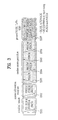
- FIG. 3 is a diagram showing physical channels used in a 3GPP system and a general signal transmission method using the same.
- FIG. 4 is a diagram to describe an antenna tilting system.
- FIG. 5 is a diagram for one example of comparing an existing antenna system and an active antenna system to each other.
- FIG. 6 is a diagram for one example of forming a UE-specific beam based on an active antenna system.
- FIG. 7 is a diagram of a 2-dimensional (2D) beam transmission scenario based on an active antenna system.
- FIGS. 8-10 show various antenna array types for the present invention.
- FIG. 11 is a diagram for explaining phase shifting error in a wideband transmission system.
- FIGS. 12 and 13 show examples of antenna system for employing the embodiments of the present invention.
- FIGS. 14 and 15 show transmitting and receiving blocks employing multiple phase shifters in OFDM system.
- FIGS. 16 and 17 show an example of preferred embodiment for pre-compensating phase shifting errors.
- FIG. 18 shows an example of one preferred embodiment of the present invention applying different phase shifting per subcarrier set.
- FIGS. 19 and 20 show examples for estimating phase shifting errors using various pilot types.
- FIG. 21 is a block diagram of a communication apparatus according to an embodiment of the present invention.
- LTE long term evolution
- LTE-A LTE-advanced
- FIG. 2 is a diagram conceptually showing a network structure of an evolved universal terrestrial radio access network (E-UTRAN).
- An E-UTRAN system is an evolved form of a legacy UTRAN system.
- the E-UTRAN includes cells (eNB) which are connected to each other via an X2 interface.
- a cell is connected to a user equipment (UE) via a radio interface and to an evolved packet core (EPC) via an S1 interface.
- UE user equipment
- EPC evolved packet core
- the EPC includes a mobility management entity (MME), a serving-gateway (S-GW), and a packet data network-gateway (PDN-GW).
- MME mobility management entity
- S-GW serving-gateway
- PDN-GW packet data network-gateway
- FIG. 3 is a diagram showing physical channels used in a 3GPP system and a general signal transmission method using the same.
- the UE When a UE is powered on or enters a new cell, the UE performs an initial cell search operation such as synchronization with an eNB (S 401 ). To this end, the UE may receive a primary synchronization channel (P-SCH) and a secondary synchronization channel (S-SCH) from the eNB to perform synchronization with the eNB and acquire information such as a cell ID. Then, the UE may receive a physical broadcast channel from the eNB to acquire broadcast information in the cell. During the initial cell search operation, the UE may receive a downlink reference signal (DL RS) so as to confirm a downlink channel state.
- P-SCH primary synchronization channel
- S-SCH secondary synchronization channel
- DL RS downlink reference signal
- the UE may receive a physical downlink control channel (PDCCH) and a physical downlink control channel (PDSCH) based on information included in the PDCCH to acquire more detailed system information (S 402 ).
- a physical downlink control channel (PDCCH)
- a physical downlink control channel (PDSCH)
- the UE may perform a random access procedure (RACH) with respect to the eNB (steps S 403 to S 406 ).
- RACH random access procedure
- the UE may transmit a specific sequence as a preamble through a physical random access channel (PRACH) (S 403 ) and receive a response message to the preamble through the PDCCH and the PDSCH corresponding thereto (S 404 ).
- PRACH physical random access channel
- the UE may further perform a contention resolution procedure.
- the UE may receive PDCCH/PDCCH from the eNB (S 407 ) and may transmit a physical uplink shared channel (PUSCH)/physical uplink control channel (PUCCH) to the eNB (S 408 ), which is a general uplink/downlink signal transmission procedure.
- PUSCH physical uplink shared channel
- PUCCH physical uplink control channel
- the UE receives downlink control information (DCI) through the PDCCH.
- DCI downlink control information
- the DCI includes control information such as resource allocation information for the UE. Different DCI formats are defined according to different usages of DCI.
- Control information transmitted from the UE to the eNB in uplink or transmitted from the eNB to the UE in downlink includes a downlink/uplink acknowledge/negative acknowledge (ACK/NACK) signal, a channel quality indicator (CQI), a precoding matrix index (PMI), a rank indicator (RI), and the like.
- ACK/NACK downlink/uplink acknowledge/negative acknowledge
- CQI channel quality indicator
- PMI precoding matrix index
- RI rank indicator
- the UE may transmit the control information such as CQI/PMI/RI through the PUSCH and/or the PUCCH.
- a compensation method considering characteristics of a phase shifter upon analog beamforming at a transmitter including a two-dimensional (2D) antenna array including a plurality of antennas.
- a phase shifter shifts the phase of an analog RF signal passing through a digital-to-analog converter (DAC) and may shift the phase in a desired direction in a relatively narrow frequency band.
- DAC digital-to-analog converter
- phase shifting values of both ends of the frequency band may be different from that of the center of the frequency band.
- phase shifting error may vary according to angle set per phase shifter.
- a method of estimating a phase difference value generated per band when phase shifting is performed by a phase shifter, at a transmitter for performing wideband analog beamforming, and pre-compensating for the phase difference in a digital signal processing procedure is proposed.
- a method of estimating a phase difference of a phase shifter and an antenna structure capable of pre-compensating for the phase difference are proposed.
- FIG. 4 is a diagram to describe an antenna tilting system.
- FIG. 4( a ) shows an antenna structure to which an antenna tilting is not applied.
- FIG. 4( b ) shows an antenna structure to which a mechanical tilting is applied.
- FIG. 4( c ) shows an antenna structure to which both a mechanical tilting and an electrical tilting are applied.
- FIG. 4( a ) and FIG. 4( b ) Comparing FIG. 4( a ) and FIG. 4( b ) to each other, regarding a mechanical tilting, as shown in FIG. 4( b ) , it is disadvantageous in that a beam direction is fixed in case of an initial installation. Moreover, regarding an electrical tilting, as shown in FIG. 4( c ) , despite that a tilting angle is changeable using an internal phase shift module, it is disadvantageous in that a very restrictive vertical beamforming is available only due to a substantially cell-fixed tilting.
- FIG. 5 is a diagram for one example of comparing an existing antenna system and an active antenna system to each other.
- FIG. 5( a ) shows an existing antenna system
- FIG. 5( b ) shows an active antenna system
- each of a plurality of antenna modules includes active devices such as a power amplifier, an RF module and the like.
- the active antenna system is capable of controlling/adjusting a power and phase for each of the antenna modules.
- a linear antenna i.e., 1-dimensional array antenna
- ULA uniform linear array
- a beam generable by beamforming exists in a 2-dimensional plane.
- PAS passive antenna system
- vertical antennas and horizontal antennas exist in the PAS based base station, since the vertical antennas are combined into one RF module, beamforming in vertical direction is impossible but the above-mentioned mechanical tilting is applicable only.
- an independent RF module is implemented for each antenna in a vertical direction, whereby a beamforming in a vertical direction is possible as well as in a horizontal direction.
- Such a beamforming is called an elevation beamforming.
- generable beams can be represented in a 3-dimensional space in vertical and horizontal directions.
- a beamforming can be named a 3-dimensional (3D) beamforming.
- the 3D beamforming is possible because the 1D array antenna structure is evolved into a 2D array antenna structure in a plane shape.
- the 3D beamforming is possible in a 3D array structure of a ring shape as well as in a planar-shaped antenna array structure.
- the 3D beamforming is characterized in that an MIMO process is performed in a 3D space owing to antenna deployments of various types instead of an existing 1D array antenna structure.
- FIG. 6 is a diagram for one example of forming a UE-specific beam based on an active antenna system.
- a beamforming is possible in case that a user equipment moves back and forth as well as in case that the user equipment moves right and left to the base station. Hence, it can be observed that a higher degree of freedom is provided to a UE-specific beamforming.
- an environment (O2I: outdoor to indoor) of a transmission from an outdoor base station to an indoor user equipment an environment (indoor hotspot) of a transmission from an indoor base station to an indoor user equipment or the like can be considered as well as an environment of a transmission from an outdoor base station to an outdoor user equipment.
- FIG. 7 is a diagram of a 2-dimensional (2D) beam transmission scenario based on an active antenna system.
- a base station needs to consider a vertical beam steering capability in consideration of various user equipment heights in accordance with a building height as well as a UE-specific horizontal beam steering capability.
- channel characteristics e.g., radio shadow/path loss variation due to a height difference, fading characteristic change, etc.
- a 3D beamforming which is evolved from a horizontal beamforming performed in a horizontal direction only based on an antenna structure of an existing linear ID array, indicates an MIMO processing scheme performed in a manner of being extended to and combined with an elevation beamforming or a vertical beamforming based on an antenna structure of multi-dimensional arrays including a planar array and the like.
- FIGS. 8-10 show various antenna array types for the present invention. Specifically, FIG. 8 shows a concept of passive antenna array (Common TRX+Common PA+Multiple N antenna). FIG. 9 shows a concept of active antenna array (Common TRX+Multiple PA+Multiple N antenna). FIG. 10 shows a concept of multiple Active antenna array (Multiple TRX+Multiple PA+Multiple N antenna).
- a power amplifier (PA) and a phase shifter may be coupled to each antenna transmitter. Accordingly, three types of active array antennas shown in FIGS. 8 to 10 may be considered.
- a common TRX means a transmission and reception signal processing block. That is, in a passive array of FIG. 8 , one RF transmission signal is branched into a plurality of antennas. Each antenna includes only a phase shifter without a PA. Accordingly, since phase shifting of the same RF signal is performed equally or differently according to antenna element, the same or individual phase shifting is possible.
- An active antenna array has a structure in which phase shifters and PAs are coupled to antenna elements in 1:1 correspondence as shown in FIG. 9 . Since a common transmission and reception signal processing block is used, the same RF signal is branched similarly to FIG. 8 .
- the active antenna array is different from the passive array in that PAs corresponding in number to the number N of antenna elements are included.
- a multiple active antenna array has a structure in which TRXs, phase shifters and PAs corresponding in number of to the number N of antenna elements are coupled. Accordingly, the multiple active antenna array has a more complex structure than those of the above-described antenna arrays but has highest flexibility for analog beam control.
- phase shifter used for the above-described antenna array systems will now be described.
- phase shift refers to a device for shifting a signal phase using an electrical or mechanical method.
- the phase shifter used herein may be a fundamental module for driving the above-described massive antenna for beam control and phase shifting of the phase array antenna as shown in FIGS. 8 to 10 .
- the method of shifting the phase at the phase shifter will now be described.
- the phase shift is added to a final RE signal processor after a baseband signal subjected to digital signal processing is converted into an analog signal by a digital-to-analog (DAC) converter and the analog signal is processed. That is, in the phase shift, signal processing per frequency band is impossible.
- the phase shifting method of the phase shifter may include the following five methods.
- one coaxial pipe expands and contracts while being inserted into and taken out of the other coaxial line.
- the phase may be consecutively changed. Low loss.
- Phase shift method 1 of electrically changing the length Line changing method
- a plurality of transmission lines having different lengths is provided and the paths thereof are changed by a switch.
- phase value may not be consecutively changed (digital). Greater loss than in mechanical method.
- phase shifter of a line changing method The phase may be changed from 0 to 337.5 in units of 22.5.
- an electrical signal is reflected from an impedance change point such that the phase thereof is changed.
- the insertion phase may be adjusted according to a value of an element connected to a middle part of a transmission line.
- Insertion loss deteriorates and impedance characteristics also deteriorate.
- Phase shift method 3 of electrically changing the length Loaded line type, hybrid coupled type
- Loaded line type This is used for a phase shifter having a phase shift amount of 45° or less.
- Hybrid Coupled Type This is used for a phase shifter having a phase shift amount of 45° or more.
- the phase is changed using reactance change when a PIN diode is turned on/off.
- phase shifting errors may occur.
- Phase shifting of the phase shifter may be generally performed in a narrow band without any problems. That is, phase shifting may be performed with respect to an analog signal of a band of 5 MHz or 10 MHz without any problems.
- phase shifter is only valid within several MHz or 10 MHz or less from the center frequency f c .
- phase shift of an analog beam occurs according to the phase value set in the phase shifter with respect to the center frequency but the value thereof may be changed with respect to the frequency band other than the center frequency band.
- FIG. 11 is a diagram for explaining phase shifting error in a wideband transmission system.
- the phase is shifted by ⁇ p in a valid range from the center of the whole frequency bandwidth but the phase value is gradually changed in the range other than the valid range. This may occur upon wideband transmission. Since phase shifting is performed through the phase shift after the baseband signal is converted into an analog signal. In this case, the phase of an analog beam is shifted according to phase value set in the phase shifter with respect to the center frequency band but the phase value may be changed with respect to the band other than the center frequency band.
- FIGS. 12 and 13 show examples of antenna system for employing the embodiments of the present invention.
- the transmitted signal converted into the analog RF signal may be sent to M phase shifters and antenna elements as shown in FIG. 12 .
- the antenna systems shown in FIGS. 12 and 13 are used.
- RF signals the phases of which are simultaneously shifted to the same phase by the phase shifters set to a single angle, may be generated or a separate digital transmission/reception signal processing block may be provided per unit including M elements to generate a mixture of RF signals, the phases of which are shifted to various phases.
- FIGS. 12 and 13 may be summarized as follows.
- Approach 2 may be regarded as an extension of Approach 1.
- TRX 1 to TRX O refer to blocks for generating the same transport blocks or information.
- each unit is virtualized via M antennas for performing the same phase shifting.
- the phase of each unit is shifted by the same phase shifting value ⁇ p using the M phase shifters and then each unit is virtualized, thereby having the transmission/reception structure shown in FIGS. 14 and 15 .
- FIGS. 14 and 15 show transmitting and receiving blocks employing multiple phase shifters in OFDM system.
- a phase shifter is located in an OFDM transmission block and phase shifting is performed via a phase shifter after a transmission symbol subjected to OFDM modulation is converted into an analog RF signal.
- a wireless channel is independent between each antenna element and a receive antenna.
- Equation 1 A discrete OFDM signal subjected to OFDM modulation may be expressed by Equation 1 below.
- x l [n] denotes an n th sample (time domain) obtained by sampling an l th OFDM symbol
- X l [k] denotes a data symbol (frequency domain) transmitted on a k th subcarrier of an l th OFDM symbol.
- l denotes an OFDM symbol index
- k denotes a subcarrier index
- n denotes a sample index of a discrete time domain
- N denotes FFT size, that is, the total number of subcarriers.
- Equation 2 Equation 2
- x l [n] denotes an n th sample (time domain) obtained by sampling an l th OFDM symbol passing through the phase shifter
- y l [n] denotes an n th sample (time domain) of an l th received OFDM symbol
- Y l [k] denotes a data symbol (frequency domain) on a k th subcarrier of an l th received OFDM symbol.
- Equation 2 two variables are added: one is a phase shifting value ⁇ p set in the phase shifter and the other is phase shifting error ⁇ k p caused by the phase shifter. Shifting error ⁇ k p varies according to phase shifting setting value ⁇ p and subcarrier, a subcarrier index ‘k’ is included in ⁇ k p .
- the received signal before last OFDM demodulation of FIG. 15 may be expressed by a discrete signal shown in Equation 3 and is expressed by an OFDM demodulation symbol as shown in Equation 4 when the signal does not pass through the phase shifter.
- h l [n], z l [n] denotes a wireless channel impulse function and AWGN noise and H l [k], Z l [k] denotes a frequency response and noise of a channel in a k th subcarrier.
- Equation 5 the received signal is demodulated in the form of Equation 5 if the signal passes through the phase shifter.
- Y l [k] H l [k]X l [k]e j2 ⁇ ( ⁇ p + ⁇ k p ) +Z l [k] [Equation 5]
- phase shifting error ⁇ k and the phase shifting setting value ⁇ p of an angle of a received signal coexist per subcarrier.
- pre-compensation precoding is performed according to the phase shifting setting value in order to compensate for phase errors occurring upon phase shifting of the phase shifter.
- FIGS. 16 and 17 show an example of preferred embodiment for pre-compensating phase shifting errors.
- phase shifting error is compensated for before a signal is branched into M antenna elements (including the phase shifter) by adding a pre-compensation block before the signal is branched into antennas by a digital processing block to pass through an IFFT block.
- phase shifter phase compensation in each subcarrier may be expressed by Equation 6.
- the digital signal is mapped to a single antenna port.
- the set phase shifting value is input to M phase shifters connected to M antenna elements as shown in FIG. 17 .
- the antenna port mapping number of FIG. 16 is equal to the total number “O” of TRX units.
- the branched signals are virtualized via the “M” antenna elements and analog beamforming is performed through the phase shifter. Accordingly, the phase shifting value ⁇ p of analog beamforming is set per antenna port.
- This setting value refers to a value commonly set with respect to the phase shifters connected to the M antenna elements. Accordingly, in pre-compensating precoding, phase shifting ⁇ k p for the phase shifting value ⁇ p per antenna port is commonly compensated for.
- a signal, to which phase shifter phase compensation is applied in each subcarrier may be expressed by Equation 6.
- y HF PS Fx+z [Equation 6]
- y denotes a received signal vector N r ⁇ 1 in a k th subcarrier
- H denotes an N r ⁇ N r channel matrix in a k th subcarrier
- F PS denotes an N r ⁇ N r phase shifter error compensation matrix (diagonal matrix) in a k th subcarrier
- F denotes a general N r ⁇ precoding matrix for beamforming in a k th subcarrier
- x denotes a transmitted signal vector ⁇ 1 in a k th subcarrier
- z denotes an AWGN noise vector N r ⁇ 1 in a k th subcarrier
- each vector and matrix may be expressed by Equation 7.
- a phase error compensation matrix of the phase shifter has a diagonal matrix and a value thereof varies according to subcarrier.
- each row does not correspond to an antenna of each unit but corresponds to each unit.
- the analog signal branched into the antennas via such a method is subjected to analog beamforming with a phase shifting value of ⁇ p set in each system after passing through a phase shifter.
- FIG. 18 shows an example of one preferred embodiment of the present invention applying different phase shifting per subcarrier set.
- phase shifting is applied in subcarrier set units having similar phase error of the pre-compensation block.
- phase shifting value ⁇ p intended by the phase shifter should be changed according to subcarrier, when the signal passes through the phase shifter, constant phase error ⁇ k p , which vary according to frequency band or k th subcarrier, may occur according to the phase shifting value ⁇ p .
- Equation 8 Equation 8
- a base station estimates shifting error according to phase setting value of a phase shifter via comparison between transmitted signals and derives phase shifting error per subcarrier to be compensated for according to phase shifting setting value.
- phase error caused by the phase shifter should be estimated.
- an entity for performing analog beamforming using a massive array antenna directly performs channel estimation. That is, when the base station performs analog beamforming using the massive antenna, a per-band phase difference between signals passing through the phase shifter may be directly compared.
- a method of, at a UE, which has acquired the phase setting value of the phase shifter, estimating phase shifting error, and feeding the phase shifting error back to a base station is proposed.
- This method uses a general pilot based channel estimation method which may be set with respect to all UEs. That is, a conventional pilot channel estimation method may be reused. In this method, all UEs may feed phase error back per subband with respect to the whole frequency band. This is because phase shifting errors caused by the phase shifter differ between subcarriers or subcarrier sets, according to the present embodiment.
- the UE performs pure channel estimation in a state in which the phase shift does not operate.
- a wireless channel is estimated per subcarrier using a least-squares method shown in Equation 10, where X l [k] denotes a signal via which a pilot signal is transmitted.
- channel estimation to which the phase shifting setting value is applied, is performed. This may be expressed by Equation 11.
- pure phase shifting error is estimated via the assumption shown in Equation 13.
- ⁇ k p ⁇ e j2 ⁇ k p ⁇ l,ps [k]/ ⁇ l [k] /( ⁇ l,ps [N/ 2]/ ⁇ l [N/ 2]) [Equation 13]
- a soft value may be transmitted without change and the result may be fed back using a quantization method. For example, a section [0, 2 ⁇ ] may be quantized into N bits to have 2 N resolutions.
- the base station uses the phase error value fed back by each UE or may use an average of the values fed back by all UEs.
- the channel estimation order according to the present embodiment may be set as follows.
- Step 3 The phase estimation value of all subcarriers is subtracted from the estimation value of the subcarrier (N/2) corresponding to the transmission band (see Equation 13) ⁇ The phase shifting error ⁇ k p is derived per subcarrier.
- Step 4 The phase shifting error is fed back to the base station per subcarrier or per subcarrier set.
- FIGS. 19 and 20 show examples for estimating phase shifting errors using various pilot types.
- FIG. 19 is an example for estimating phase shifting errors using pilot pattern transmitted through the whole bandwidth
- FIG. 20 is an example for estimating phase shifting errors using pilot pattern transmitted through a subband of the frequency band.
- the phase shifter simultaneously changes the whole phase of the analog RF signal. Accordingly, the digital processing, block can compensate for the phase error of the whole bandwidth. Accordingly, each UE may derive phase error caused by the phase shifter based on channel estimation for the whole system bandwidth, not based on bandwidth allocated thereto.
- the base station may allocate a pilot signal to the whole transmission bandwidth and perform estimation.
- a pilot pattern for the whole bandwidth may be defined and the UE may perform interpolation between the detected pilot signals and estimate phase shifting errors for all channels.
- a method of setting a pilot signal per subband to perform estimation and periodically and repeatedly transmitting the pilot signal may be used.
- each UE may derive phase error caused by the phase shifter based on channel estimation for the subband allocated thereto.
- the base station defines a pilot allocation pattern such that channel estimation for the whole bandwidth is possible or channel estimation for the whole bandwidth is possible over several symbols. For example, as shown in FIG. 20 , different patterns are defined per subband and channel and phase shifting error for the whole bandwidth may be estimated over three OFDM symbols. Even at this time, interpolation between pilot signals may be performed and phase shifting error for all channels may be estimated.
- the present invention proposes a compensation method considering characteristics of a phase shifter upon analog beamforming at a transmitter including a 2-dimensional antenna array including a plurality of antennas is proposed.
- FIG. 21 is a block diagram of a communication apparatus according to an embodiment of the present invention.
- the apparatus shown in FIG. 21 can be a user equipment (UE) and/or eNB adapted to perform the above mechanism, but it can be any apparatus for performing the same operation.
- UE user equipment
- eNB evolved node B
- the apparatus may comprises a DSP/microprocessor ( 110 ) and RF module (transceiver; 135 ).
- the DSP/microprocessor ( 110 ) is electrically connected with the transceiver ( 135 ) and controls it.
- the apparatus may further include power management module ( 105 ), battery ( 155 ), display ( 115 ), keypad ( 120 ), SEM card ( 125 ), memory device ( 130 ), speaker ( 145 ) and input device ( 150 ), based on its implementation and designer's choice.
Landscapes
- Engineering & Computer Science (AREA)
- Computer Networks & Wireless Communication (AREA)
- Signal Processing (AREA)
- Physics & Mathematics (AREA)
- Electromagnetism (AREA)
- Radio Transmission System (AREA)
- Mobile Radio Communication Systems (AREA)
Abstract
Description
-
- Unit 1: Single TRX+‘M’ Phase-shifters with same δp
1 - Unit 2: Single TRX+‘M’ Phase-shifters with same δp
2 - Unit O: Single TRX+‘M’ Phase-shifters with same δp
O
- Unit 1: Single TRX+‘M’ Phase-shifters with same δp
Y l [k]=H l [k]X l [k]e j2π(δ
y=HF PS Fx+z [Equation 6]
δk p→δ0 p=δ1 p=δ2 p . . . =δN−1 p [Equation 8]
e j2π(δ
δk p →e j2πδ
Claims (9)
Priority Applications (1)
| Application Number | Priority Date | Filing Date | Title |
|---|---|---|---|
| US15/033,827 US9825687B2 (en) | 2013-11-08 | 2014-05-02 | Pre-compensation of the phase shifting error |
Applications Claiming Priority (3)
| Application Number | Priority Date | Filing Date | Title |
|---|---|---|---|
| US201361901454P | 2013-11-08 | 2013-11-08 | |
| PCT/KR2014/003938 WO2015068919A1 (en) | 2013-11-08 | 2014-05-02 | Pre-compensation of the phase shifting error |
| US15/033,827 US9825687B2 (en) | 2013-11-08 | 2014-05-02 | Pre-compensation of the phase shifting error |
Publications (2)
| Publication Number | Publication Date |
|---|---|
| US20160308597A1 US20160308597A1 (en) | 2016-10-20 |
| US9825687B2 true US9825687B2 (en) | 2017-11-21 |
Family
ID=53041666
Family Applications (1)
| Application Number | Title | Priority Date | Filing Date |
|---|---|---|---|
| US15/033,827 Active US9825687B2 (en) | 2013-11-08 | 2014-05-02 | Pre-compensation of the phase shifting error |
Country Status (3)
| Country | Link |
|---|---|
| US (1) | US9825687B2 (en) |
| KR (1) | KR101801589B1 (en) |
| WO (1) | WO2015068919A1 (en) |
Families Citing this family (12)
| Publication number | Priority date | Publication date | Assignee | Title |
|---|---|---|---|---|
| US10056990B2 (en) * | 2014-08-12 | 2018-08-21 | Denki Kogyo Company, Limited | Base station antenna apparatus for mobile communication system |
| WO2017022921A1 (en) * | 2015-07-31 | 2017-02-09 | 엘지전자 주식회사 | Method for determining precoder for hybrid beamforming in wireless communication system, and apparatus therefor |
| WO2017107063A1 (en) * | 2015-12-22 | 2017-06-29 | 华为技术有限公司 | Communication apparatus and wireless communication device |
| US9967014B1 (en) | 2016-11-09 | 2018-05-08 | Facebook, Inc. | Beamforming in antenna systems |
| US10470242B2 (en) | 2016-11-18 | 2019-11-05 | Qualcomm Incorporated | Phase compensation reference signal in NR-SS CoMP |
| WO2017063614A2 (en) * | 2016-11-30 | 2017-04-20 | Telefonaktiebolaget Lm Ericsson (Publ) | Method and device for transmitting information |
| CN109510791B (en) * | 2017-09-15 | 2024-10-11 | 华为技术有限公司 | Transmission method and transmission device |
| KR102388027B1 (en) | 2018-12-26 | 2022-04-19 | 삼성전자 주식회사 | A method for testing a wireless communication module, and an electronic device including the wireless communication module |
| IL274890B2 (en) | 2020-05-24 | 2024-02-01 | Elta Systems Ltd | System and method for transmitting radio wave radiation |
| WO2022010012A1 (en) * | 2020-07-09 | 2022-01-13 | 엘지전자 주식회사 | Beamforming method and device in wireless communication system |
| CN116388885B (en) * | 2022-12-31 | 2026-02-17 | 电子科技大学 | A delay compensation method for a terahertz fiber optic communication system |
| KR102769801B1 (en) * | 2023-03-24 | 2025-02-17 | 아주대학교산학협력단 | Transmission method and apparatus based on precoding of frequency diverse array antenna |
Citations (10)
| Publication number | Priority date | Publication date | Assignee | Title |
|---|---|---|---|---|
| US20050201483A1 (en) | 2004-03-12 | 2005-09-15 | Edmund Coersmeier | Error adjustment for multi-antenna transmitter |
| US20070098097A1 (en) * | 2005-10-28 | 2007-05-03 | Samsung Electronics Co., Ltd. | System and method for enhancing the performance of wireless communication systems |
| US20080130790A1 (en) | 2004-07-30 | 2008-06-05 | Antionio Forenza | System and method for distributed input distributed output wireless communications |
| US20100027696A1 (en) * | 2006-11-06 | 2010-02-04 | Lg Electronics | Method of data transmission in a wireless communication system |
| US20100173660A1 (en) * | 2009-01-07 | 2010-07-08 | Samsung Electronics Co., Ltd. | COORDINATED MULTIPOINT (CoMP) JOINT TRANSMISSION USING CHANNEL INFORMATION FEEDBACK AND HIGHER RANK DEDICATED BEAM-FORMING |
| US20120033759A1 (en) * | 2009-01-30 | 2012-02-09 | Telefonaktiebolaget Lm Ericsson (Publ) | Phase Calibration and Erroneous Cabling Detection for a Multi-Antenna Radio Base Station |
| US20130002488A1 (en) * | 2011-06-30 | 2013-01-03 | Sony Corporation | Wideband beam forming device; wideband beam steering device and corresponding methods |
| US20130034182A1 (en) | 2006-07-06 | 2013-02-07 | Lg Electronics Inc. | Method and apparatus for correcting errors in a multiple subcarriers communication system using multiple antennas |
| US20130039401A1 (en) * | 2011-08-11 | 2013-02-14 | Samsung Electronics Co., Ltd. | Method and aparatus for mixed analog/digital beamforming |
| US20130177102A1 (en) * | 2010-09-17 | 2013-07-11 | Pantech Co., Ltd | Apparatus and method for transmitting data using multiple antennas and beamforming |
-
2014
- 2014-05-02 WO PCT/KR2014/003938 patent/WO2015068919A1/en not_active Ceased
- 2014-05-02 US US15/033,827 patent/US9825687B2/en active Active
- 2014-05-02 KR KR1020167010204A patent/KR101801589B1/en not_active Expired - Fee Related
Patent Citations (10)
| Publication number | Priority date | Publication date | Assignee | Title |
|---|---|---|---|---|
| US20050201483A1 (en) | 2004-03-12 | 2005-09-15 | Edmund Coersmeier | Error adjustment for multi-antenna transmitter |
| US20080130790A1 (en) | 2004-07-30 | 2008-06-05 | Antionio Forenza | System and method for distributed input distributed output wireless communications |
| US20070098097A1 (en) * | 2005-10-28 | 2007-05-03 | Samsung Electronics Co., Ltd. | System and method for enhancing the performance of wireless communication systems |
| US20130034182A1 (en) | 2006-07-06 | 2013-02-07 | Lg Electronics Inc. | Method and apparatus for correcting errors in a multiple subcarriers communication system using multiple antennas |
| US20100027696A1 (en) * | 2006-11-06 | 2010-02-04 | Lg Electronics | Method of data transmission in a wireless communication system |
| US20100173660A1 (en) * | 2009-01-07 | 2010-07-08 | Samsung Electronics Co., Ltd. | COORDINATED MULTIPOINT (CoMP) JOINT TRANSMISSION USING CHANNEL INFORMATION FEEDBACK AND HIGHER RANK DEDICATED BEAM-FORMING |
| US20120033759A1 (en) * | 2009-01-30 | 2012-02-09 | Telefonaktiebolaget Lm Ericsson (Publ) | Phase Calibration and Erroneous Cabling Detection for a Multi-Antenna Radio Base Station |
| US20130177102A1 (en) * | 2010-09-17 | 2013-07-11 | Pantech Co., Ltd | Apparatus and method for transmitting data using multiple antennas and beamforming |
| US20130002488A1 (en) * | 2011-06-30 | 2013-01-03 | Sony Corporation | Wideband beam forming device; wideband beam steering device and corresponding methods |
| US20130039401A1 (en) * | 2011-08-11 | 2013-02-14 | Samsung Electronics Co., Ltd. | Method and aparatus for mixed analog/digital beamforming |
Non-Patent Citations (1)
| Title |
|---|
| PCT International Application No. PCT/KR2014/003938, Written Opinion of the International Searching Authority dated Aug. 22, 2014, 14 pages. |
Also Published As
| Publication number | Publication date |
|---|---|
| WO2015068919A1 (en) | 2015-05-14 |
| KR20160067203A (en) | 2016-06-13 |
| KR101801589B1 (en) | 2017-11-27 |
| US20160308597A1 (en) | 2016-10-20 |
Similar Documents
| Publication | Publication Date | Title |
|---|---|---|
| US9825687B2 (en) | Pre-compensation of the phase shifting error | |
| RU2720462C1 (en) | Method and device for uplink data transmission in a wireless communication system | |
| US10411768B2 (en) | Method and apparatus for transmitting and receiving feedback information in mobile communication system based on 2 dimensional massive MIMO | |
| US10305660B2 (en) | Method and apparatus for allocating wireless resources | |
| US10136337B2 (en) | Method and apparatus for acquiring channel state information in antenna array | |
| CN105684323B (en) | Method and apparatus for transmitting signal in wireless communication system | |
| US9819407B2 (en) | Pre-compensation of the phase shifting error | |
| EP2566266A1 (en) | Wireless communication method, wireless base station, mobile terminal, and wireless communication system | |
| CN108463952B (en) | Method, system and device | |
| US10020867B2 (en) | Interference management for mobile relay in full-duplex radio communication system | |
| WO2022012199A1 (en) | User equipment-assisted beam broadening | |
| US20220190897A1 (en) | Codebook for distributed mimo transmission | |
| US20250125889A1 (en) | Calibration for wireless communication network | |
| US20260066971A1 (en) | Csi and calibration reporting | |
| JP7308152B2 (en) | Method and terminal for transmitting feedback information in wireless communication system | |
| US20250112711A1 (en) | Calibration for wireless communication network | |
| US20240172197A1 (en) | Method and apparatus to support multiple numerologies in wireless communication systems | |
| WO2025160702A1 (en) | Resource aggregation for increased quantity of channel state information reference signal ports | |
| US20240022300A1 (en) | Method and apparatus for configuring measurement and reporting settings | |
| US20260032495A1 (en) | Calibration and csi reporting | |
| WO2024132377A1 (en) | Method and network node for transmission of wideband signals towards a wireless device through time domain beamforming | |
| CN120814188A (en) | Quantizing time-domain channel properties | |
| CN120693837A (en) | Channel state information reference signal for wireless communications | |
| JPWO2023146441A5 (en) |
Legal Events
| Date | Code | Title | Description |
|---|---|---|---|
| AS | Assignment |
Owner name: LG ELECTRONICS INC., KOREA, REPUBLIC OF Free format text: ASSIGNMENT OF ASSIGNORS INTEREST;ASSIGNORS:KIM, KITAE;CHUNG, JAEHOON;KANG, JIWON;AND OTHERS;SIGNING DATES FROM 20160328 TO 20160419;REEL/FRAME:038438/0106 |
|
| STCF | Information on status: patent grant |
Free format text: PATENTED CASE |
|
| MAFP | Maintenance fee payment |
Free format text: PAYMENT OF MAINTENANCE FEE, 4TH YEAR, LARGE ENTITY (ORIGINAL EVENT CODE: M1551); ENTITY STATUS OF PATENT OWNER: LARGE ENTITY Year of fee payment: 4 |
|
| MAFP | Maintenance fee payment |
Free format text: PAYMENT OF MAINTENANCE FEE, 8TH YEAR, LARGE ENTITY (ORIGINAL EVENT CODE: M1552); ENTITY STATUS OF PATENT OWNER: LARGE ENTITY Year of fee payment: 8 |