US982407A - Electrode for flaming-arc lamps. - Google Patents
Electrode for flaming-arc lamps. Download PDFInfo
- Publication number
- US982407A US982407A US49178409A US1909491784A US982407A US 982407 A US982407 A US 982407A US 49178409 A US49178409 A US 49178409A US 1909491784 A US1909491784 A US 1909491784A US 982407 A US982407 A US 982407A
- Authority
- US
- United States
- Prior art keywords
- electrode
- wire
- flaming
- arc lamps
- clamp
- Prior art date
- Legal status (The legal status is an assumption and is not a legal conclusion. Google has not performed a legal analysis and makes no representation as to the accuracy of the status listed.)
- Expired - Lifetime
Links
- 238000010276 construction Methods 0.000 description 7
- 239000011248 coating agent Substances 0.000 description 6
- 238000000576 coating method Methods 0.000 description 6
- OKTJSMMVPCPJKN-UHFFFAOYSA-N Carbon Chemical compound [C] OKTJSMMVPCPJKN-UHFFFAOYSA-N 0.000 description 5
- 229910052799 carbon Inorganic materials 0.000 description 5
- 239000002184 metal Substances 0.000 description 3
- 229910052751 metal Inorganic materials 0.000 description 3
- 229910052802 copper Inorganic materials 0.000 description 2
- 239000010949 copper Substances 0.000 description 2
- 235000019353 potassium silicate Nutrition 0.000 description 2
- 108010085990 projectin Proteins 0.000 description 2
- 150000003839 salts Chemical class 0.000 description 2
- NTHWMYGWWRZVTN-UHFFFAOYSA-N sodium silicate Chemical compound [Na+].[Na+].[O-][Si]([O-])=O NTHWMYGWWRZVTN-UHFFFAOYSA-N 0.000 description 2
- 206010010071 Coma Diseases 0.000 description 1
- RYGMFSIKBFXOCR-UHFFFAOYSA-N Copper Chemical compound [Cu] RYGMFSIKBFXOCR-UHFFFAOYSA-N 0.000 description 1
- 239000009180 Flamin Substances 0.000 description 1
- ATJFFYVFTNAWJD-UHFFFAOYSA-N Tin Chemical compound [Sn] ATJFFYVFTNAWJD-UHFFFAOYSA-N 0.000 description 1
- HCHKCACWOHOZIP-UHFFFAOYSA-N Zinc Chemical compound [Zn] HCHKCACWOHOZIP-UHFFFAOYSA-N 0.000 description 1
- 239000000956 alloy Substances 0.000 description 1
- 229910045601 alloy Inorganic materials 0.000 description 1
- 150000001879 copper Chemical class 0.000 description 1
- 238000007598 dipping method Methods 0.000 description 1
- 238000006073 displacement reaction Methods 0.000 description 1
- 238000009713 electroplating Methods 0.000 description 1
- 238000000034 method Methods 0.000 description 1
- 238000009877 rendering Methods 0.000 description 1
- 229910000679 solder Inorganic materials 0.000 description 1
- 239000011701 zinc Substances 0.000 description 1
- 229910052725 zinc Inorganic materials 0.000 description 1
Images
Classifications
-
- H—ELECTRICITY
- H01—ELECTRIC ELEMENTS
- H01J—ELECTRIC DISCHARGE TUBES OR DISCHARGE LAMPS
- H01J1/00—Details of electrodes, of magnetic control means, of screens, or of the mounting or spacing thereof, common to two or more basic types of discharge tubes or lamps
- H01J1/02—Main electrodes
- H01J1/13—Solid thermionic cathodes
- H01J1/15—Cathodes heated directly by an electric current
Definitions
- MINER W. ALLEN and WALLACE T. CoNN both citizens of the United States, and both residing at Lakewood, inthe county of Cuyahoga and State of Ohio, have invented certain new and useful Improvements'in Electrodes for Flaming-Arc Lamps, of which the following is a full, clear,and exact description.
- This invention relates to electrodes for flaming arc lamps, and particularly to electrodes which on account of their low conductivity, due largely to the fact that they have rather small cross sectional areas, are provided each with a metallic Wire extending from end to end to decrease the resistance to the passage of current, such electrodes being commonly formed of a carbon shell and a central core, mainly of powdered carbon bound together by water glass and some color producing salt.
- the wire is extended beyond the end of the same, and generally the end is flattened and bent over along the side of the electrode so that it may be engaged by the clamp which holds the electrode, the end of the wire being flattened in order that the clamp may grasp the electrode firmly and so that there will be fairly large surfaces of the clamp and flattened wire in contact.
- the present invention relates particularl to the connection between the projecting end of the wire and the electrode proper, and has for its object to overcome a number of obj ectionable features of the constructions heretofore employed.
- the invention aims to attach the end of the wire to the electrode in a manner such that there will be a better electrical mechanical connection between the wire and the electrode, and to provide a connection which prevents the wire from being accidentally withdrawn from the electrode; which does away with any liability of the end of the wire being broken and the eiiiciency of the connection both mechanically and electrically destroyed, as is the case with prior constructions, and which does not prevent any part of the clamp engaging the surface of the electrode, as is the case when the end of the wire extends along the side of the electrode.
- A represents the core and B the shell of the electrode; the core A being referably formed of powdered carbon bound together by Water glass and some other color producing salt, and the shell being formed of carbon as in the electrodes heretofore constructed, and C represents a wire passing through a hole, in said electrode which extends from end to end, and the upper end of the wire projects from said hole.
- the electrode has "electro-plated upon its end, and, if desired, for a short distance down from the end, a coating 1) of copper.
- the projecting end 0 of the wire is then bent over onto the end of the electrode and against this copper coating, and is mechanically connected therewith by either being soldered thereto or by some equivalent method, as, for example, by dipping the end of the electrode either into a bath of molten tin or molten zinc, or the like, or by electro-plating.
- Fi 3 1s The construction shown in Fi 3 1s as follows: The core at the upper en of the electrode is removed fora short distance,say one-half inch, more or less,and then the end of the wire which projects from the u per end of the electrode is bent back upon 1tself, and its end inserted into the hole produced by so removing the core. Then the molten solder E or some other molten metal or alloy is poured into the hole around the wire, which, as in the former case, makes both a mechanical and an electrical connection between the projecting end of the wire and the electrode. In neither construction, however, does the wire extend over the end of the electrode and down against its side,
- An electrode forfiamin arc lamps having a wire extended throug said electrode from end to end and projected from the top thereof, said projectin end being connected both mechanically an electrically to said 2.
- An electrode for flaming arc lamps having a wire extended through said electrode nesses.
- An electrode for flamin arc lamps having a wire extended througfisaid electrode from end to end and projected from the top thereof, said electrode having a metallic coating applied to its upper end, and the projecting end of said wire being mechani-' metallic coating.
Landscapes
- Connections Effected By Soldering, Adhesion, Or Permanent Deformation (AREA)
Description
M. W. 'ALLEN & W. T. 001111.
ELECTRODE FOR FLAMING ARO EAMPS.
APPLICATION FILED APB..23, 1909.
Patented Jan.24, 1911.
unrrnn s'rA'rEs PATENT OFFICE MINER w. ALLEN AND WALLACE-r. coma, or LAKEWOOD, onro, assienons 'ro NA-.
'IIONQAL CARBON COMPANY, OF CLEVELAND, 01-110, A CORPORATION OF NEW JERSEY.
ELECTRODE FOR FLAMING-ARC LAMPS.
Specification of Letters Patent. I Application filed April 23, 1909. Serial No. 491,784.
Patented Jan. 24, 1911.
To all whom it may concern:
Be it known that we, MINER W. ALLEN and WALLACE T. CoNN, both citizens of the United States, and both residing at Lakewood, inthe county of Cuyahoga and State of Ohio, have invented certain new and useful Improvements'in Electrodes for Flaming-Arc Lamps, of which the following is a full, clear,and exact description.
This invention relates to electrodes for flaming arc lamps, and particularly to electrodes which on account of their low conductivity, due largely to the fact that they have rather small cross sectional areas, are provided each with a metallic Wire extending from end to end to decrease the resistance to the passage of current, such electrodes being commonly formed of a carbon shell and a central core, mainly of powdered carbon bound together by water glass and some color producing salt. In an electrode of this 'type,-the wire is extended beyond the end of the same, and generally the end is flattened and bent over along the side of the electrode so that it may be engaged by the clamp which holds the electrode, the end of the wire being flattened in order that the clamp may grasp the electrode firmly and so that there will be fairly large surfaces of the clamp and flattened wire in contact. Y I
The present invention relates particularl to the connection between the projecting end of the wire and the electrode proper, and has for its object to overcome a number of obj ectionable features of the constructions heretofore employed.
More partlcularly, the invention aims to attach the end of the wire to the electrode in a manner such that there will be a better electrical mechanical connection between the wire and the electrode, and to provide a connection which prevents the wire from being accidentally withdrawn from the electrode; which does away with any liability of the end of the wire being broken and the eiiiciency of the connection both mechanically and electrically destroyed, as is the case with prior constructions, and which does not prevent any part of the clamp engaging the surface of the electrode, as is the case when the end of the wire extends along the side of the electrode. 1
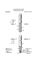
In an electrode embodying the present inprojects from the a side elevation partly sectioned of another embodiment of the invention; and Fig. 4 is an end View of the same.
Referring to the parts by letters, A represents the core and B the shell of the electrode; the core A being referably formed of powdered carbon bound together by Water glass and some other color producing salt, and the shell being formed of carbon as in the electrodes heretofore constructed, and C represents a wire passing through a hole, in said electrode which extends from end to end, and the upper end of the wire projects from said hole.
In the construction shown in Figs. 1 and 2 the electrode has "electro-plated upon its end, and, if desired, for a short distance down from the end, a coating 1) of copper. The projecting end 0 of the wire is then bent over onto the end of the electrode and against this copper coating, and is mechanically connected therewith by either being soldered thereto or by some equivalent method, as, for example, by dipping the end of the electrode either into a bath of molten tin or molten zinc, or the like, or by electro-plating.
The construction shown in Fi 3 1s as follows: The core at the upper en of the electrode is removed fora short distance,say one-half inch, more or less,and then the end of the wire which projects from the u per end of the electrode is bent back upon 1tself, and its end inserted into the hole produced by so removing the core. Then the molten solder E or some other molten metal or alloy is poured into the hole around the wire, which, as in the former case, makes both a mechanical and an electrical connection between the projecting end of the wire and the electrode. In neither construction, however, does the wire extend over the end of the electrode and down against its side,
wherefore said wire does not in any degree interfere with the proper gr pping) of the electrode by the clamp. The descri ed connection of the wire-w1th the electrodeat the end thereof does, however, serve to hold the 7 wire against accidental displacement. With either or any specific embodiment of the invention, it is unnecessary to flatten the wire,
although it may be flattened if desired; and
particularly it is-unnecessary that the flattened wire should be bent down against the side of the electrode with. danger of breaking it in so doing, and rendering it exceedelectrode.
in ly likely that in handling the electrode th1s bent flattened end will be broken off.
It is thought that the best construction is that in which anexternal coating of metal is applied to the end and a short distance down the side of the electrode, and the projectin end of said wire is electrically connecte with said coating. With this construction the clamp will grasp the coated end'of the electrode,'and thereby through it said clamp will have a good electrical connection with the wire.
Having described our invention, we claim: 1. An electrode forfiamin arc lamps having a wire extended throug said electrode from end to end and projected from the top thereof, said projectin end being connected both mechanically an electrically to said 2. An electrode for flaming arc lamps having a wire extended through said electrode nesses.
from end to end and projected from the top thereof, said projecting end bein bent down against the top. of the electr e and embedded in metal intimately attached. thereto and thereby connected tosaid top both mechanically and electrically.
3. An electrode for flamin arc lamps having a wire extended througfisaid electrode from end to end and projected from the top thereof, said electrode having a metallic coating applied to its upper end, and the projecting end of said wire being mechani-' metallic coating.
In testimony whereof, we hereunto'aflix our signatures in the presence of two wit- MINER W. ALLEN. WALLACE T. CONN.
Witnesses:
0. W. SANFORD GEO. M. SMITH.
Priority Applications (1)
| Application Number | Priority Date | Filing Date | Title |
|---|---|---|---|
| US49178409A US982407A (en) | 1909-04-23 | 1909-04-23 | Electrode for flaming-arc lamps. |
Applications Claiming Priority (1)
| Application Number | Priority Date | Filing Date | Title |
|---|---|---|---|
| US49178409A US982407A (en) | 1909-04-23 | 1909-04-23 | Electrode for flaming-arc lamps. |
Publications (1)
| Publication Number | Publication Date |
|---|---|
| US982407A true US982407A (en) | 1911-01-24 |
Family
ID=3050767
Family Applications (1)
| Application Number | Title | Priority Date | Filing Date |
|---|---|---|---|
| US49178409A Expired - Lifetime US982407A (en) | 1909-04-23 | 1909-04-23 | Electrode for flaming-arc lamps. |
Country Status (1)
| Country | Link |
|---|---|
| US (1) | US982407A (en) |
-
1909
- 1909-04-23 US US49178409A patent/US982407A/en not_active Expired - Lifetime
Similar Documents
| Publication | Publication Date | Title |
|---|---|---|
| JP2007531208A (en) | Method for bonding a terminal element to a conductor made of aluminum, and a conductor manufactured by this method | |
| JP3208923U (en) | Anti-surge winding resistor | |
| US1830084A (en) | Terminal for resistors | |
| US982407A (en) | Electrode for flaming-arc lamps. | |
| US1970804A (en) | Electrode for electrolytic baths | |
| US2509020A (en) | Electrical contact member and method of making the same | |
| WO2016039305A1 (en) | Protection element | |
| US1225297A (en) | Connector and connection for storage batteries. | |
| US1686474A (en) | Self-baking electrode | |
| US497793A (en) | Samuel b | |
| US1279192A (en) | Electrode. | |
| US2594255A (en) | Anticorrosion mounting for electric immersion heaters | |
| US2667606A (en) | Capacitor and terminal lead therefor | |
| US1150919A (en) | Storage-battery connector. | |
| US1765137A (en) | Galvanic battery | |
| US1148189A (en) | Metal coating for arc-light electrodes. | |
| US661669A (en) | Connecting conductors to carbon brushes. | |
| US563319A (en) | Charles e | |
| US1005199A (en) | Battery-connector. | |
| US2801197A (en) | Electric terminal | |
| US2077522A (en) | Battery connecter | |
| WO2018021228A1 (en) | Electrical connection component | |
| US1316034A (en) | Assigkfob | |
| US1328147A (en) | Spark-plug | |
| US1202020A (en) | Battery connection. |