US9821799B2 - Vehicle pump condition response method and assembly - Google Patents

Vehicle pump condition response method and assembly Download PDF

Info

Publication number
US9821799B2
US9821799B2 US15/046,756 US201615046756A US9821799B2 US 9821799 B2 US9821799 B2 US 9821799B2 US 201615046756 A US201615046756 A US 201615046756A US 9821799 B2 US9821799 B2 US 9821799B2
Authority
US
United States
Prior art keywords
pump
engine
stop
cycle
condition
Prior art date
Legal status (The legal status is an assumption and is not a legal conclusion. Google has not performed a legal analysis and makes no representation as to the accuracy of the status listed.)
Active
Application number
US15/046,756
Other versions
US20170240166A1 (en
Inventor
Hafiz Shafeek Khafagy
Brandon David Lint
Tim John Kropf
William Rey Patterson, JR.
Edward Katynski
Richard Reynolds Hathaway
Current Assignee (The listed assignees may be inaccurate. Google has not performed a legal analysis and makes no representation or warranty as to the accuracy of the list.)
Ford Global Technologies LLC
Original Assignee
Ford Global Technologies LLC
Priority date (The priority date is an assumption and is not a legal conclusion. Google has not performed a legal analysis and makes no representation as to the accuracy of the date listed.)
Filing date
Publication date
Application filed by Ford Global Technologies LLC filed Critical Ford Global Technologies LLC
Priority to US15/046,756 priority Critical patent/US9821799B2/en
Assigned to FORD GLOBAL TECHNOLOGIES, LLC reassignment FORD GLOBAL TECHNOLOGIES, LLC ASSIGNMENT OF ASSIGNORS INTEREST (SEE DOCUMENT FOR DETAILS). Assignors: HATHAWAY, RICHARD REYNOLDS, KATYNSKI, EDWARD, KHAFAGY, HAFIZ SHAFEEK, Kropf, Tim John, LINT, BRANDON DAVID, PATTERSON, WILLIAM REY, JR.
Priority to CN201710076877.2A priority patent/CN107089232B/en
Priority to DE102017103218.5A priority patent/DE102017103218B4/en
Publication of US20170240166A1 publication Critical patent/US20170240166A1/en
Application granted granted Critical
Publication of US9821799B2 publication Critical patent/US9821799B2/en
Active legal-status Critical Current
Anticipated expiration legal-status Critical

Links

Images

Classifications

    • FMECHANICAL ENGINEERING; LIGHTING; HEATING; WEAPONS; BLASTING
    • F02COMBUSTION ENGINES; HOT-GAS OR COMBUSTION-PRODUCT ENGINE PLANTS
    • F02NSTARTING OF COMBUSTION ENGINES; STARTING AIDS FOR SUCH ENGINES, NOT OTHERWISE PROVIDED FOR
    • F02N11/00Starting of engines by means of electric motors
    • F02N11/08Circuits specially adapted for starting of engines
    • F02N11/0814Circuits specially adapted for starting of engines comprising means for controlling automatic idle-start-stop
    • F02N11/0818Conditions for starting or stopping the engine or for deactivating the idle-start-stop mode
    • F02N11/0833Vehicle conditions
    • BPERFORMING OPERATIONS; TRANSPORTING
    • B60VEHICLES IN GENERAL
    • B60WCONJOINT CONTROL OF VEHICLE SUB-UNITS OF DIFFERENT TYPE OR DIFFERENT FUNCTION; CONTROL SYSTEMS SPECIALLY ADAPTED FOR HYBRID VEHICLES; ROAD VEHICLE DRIVE CONTROL SYSTEMS FOR PURPOSES NOT RELATED TO THE CONTROL OF A PARTICULAR SUB-UNIT
    • B60W20/00Control systems specially adapted for hybrid vehicles
    • B60W20/50Control strategies for responding to system failures, e.g. for fault diagnosis, failsafe operation or limp mode
    • BPERFORMING OPERATIONS; TRANSPORTING
    • B60VEHICLES IN GENERAL
    • B60WCONJOINT CONTROL OF VEHICLE SUB-UNITS OF DIFFERENT TYPE OR DIFFERENT FUNCTION; CONTROL SYSTEMS SPECIALLY ADAPTED FOR HYBRID VEHICLES; ROAD VEHICLE DRIVE CONTROL SYSTEMS FOR PURPOSES NOT RELATED TO THE CONTROL OF A PARTICULAR SUB-UNIT
    • B60W10/00Conjoint control of vehicle sub-units of different type or different function
    • B60W10/04Conjoint control of vehicle sub-units of different type or different function including control of propulsion units
    • B60W10/06Conjoint control of vehicle sub-units of different type or different function including control of propulsion units including control of combustion engines
    • BPERFORMING OPERATIONS; TRANSPORTING
    • B60VEHICLES IN GENERAL
    • B60WCONJOINT CONTROL OF VEHICLE SUB-UNITS OF DIFFERENT TYPE OR DIFFERENT FUNCTION; CONTROL SYSTEMS SPECIALLY ADAPTED FOR HYBRID VEHICLES; ROAD VEHICLE DRIVE CONTROL SYSTEMS FOR PURPOSES NOT RELATED TO THE CONTROL OF A PARTICULAR SUB-UNIT
    • B60W10/00Conjoint control of vehicle sub-units of different type or different function
    • B60W10/30Conjoint control of vehicle sub-units of different type or different function including control of auxiliary equipment, e.g. air-conditioning compressors or oil pumps
    • BPERFORMING OPERATIONS; TRANSPORTING
    • B60VEHICLES IN GENERAL
    • B60WCONJOINT CONTROL OF VEHICLE SUB-UNITS OF DIFFERENT TYPE OR DIFFERENT FUNCTION; CONTROL SYSTEMS SPECIALLY ADAPTED FOR HYBRID VEHICLES; ROAD VEHICLE DRIVE CONTROL SYSTEMS FOR PURPOSES NOT RELATED TO THE CONTROL OF A PARTICULAR SUB-UNIT
    • B60W30/00Purposes of road vehicle drive control systems not related to the control of a particular sub-unit, e.g. of systems using conjoint control of vehicle sub-units
    • B60W30/18Propelling the vehicle
    • B60W30/18009Propelling the vehicle related to particular drive situations
    • B60W30/18018Start-stop drive, e.g. in a traffic jam
    • BPERFORMING OPERATIONS; TRANSPORTING
    • B60VEHICLES IN GENERAL
    • B60WCONJOINT CONTROL OF VEHICLE SUB-UNITS OF DIFFERENT TYPE OR DIFFERENT FUNCTION; CONTROL SYSTEMS SPECIALLY ADAPTED FOR HYBRID VEHICLES; ROAD VEHICLE DRIVE CONTROL SYSTEMS FOR PURPOSES NOT RELATED TO THE CONTROL OF A PARTICULAR SUB-UNIT
    • B60W50/00Details of control systems for road vehicle drive control not related to the control of a particular sub-unit, e.g. process diagnostic or vehicle driver interfaces
    • B60W50/02Ensuring safety in case of control system failures, e.g. by diagnosing, circumventing or fixing failures
    • B60W50/032Fixing failures by repairing failed parts, e.g. loosening a sticking valve
    • FMECHANICAL ENGINEERING; LIGHTING; HEATING; WEAPONS; BLASTING
    • F02COMBUSTION ENGINES; HOT-GAS OR COMBUSTION-PRODUCT ENGINE PLANTS
    • F02DCONTROLLING COMBUSTION ENGINES
    • F02D41/00Electrical control of supply of combustible mixture or its constituents
    • F02D41/02Circuit arrangements for generating control signals
    • F02D41/04Introducing corrections for particular operating conditions
    • F02D41/042Introducing corrections for particular operating conditions for stopping the engine
    • FMECHANICAL ENGINEERING; LIGHTING; HEATING; WEAPONS; BLASTING
    • F02COMBUSTION ENGINES; HOT-GAS OR COMBUSTION-PRODUCT ENGINE PLANTS
    • F02DCONTROLLING COMBUSTION ENGINES
    • F02D41/00Electrical control of supply of combustible mixture or its constituents
    • F02D41/02Circuit arrangements for generating control signals
    • F02D41/04Introducing corrections for particular operating conditions
    • F02D41/06Introducing corrections for particular operating conditions for engine starting or warming up
    • F02D41/062Introducing corrections for particular operating conditions for engine starting or warming up for starting
    • F02D41/065Introducing corrections for particular operating conditions for engine starting or warming up for starting at hot start or restart
    • FMECHANICAL ENGINEERING; LIGHTING; HEATING; WEAPONS; BLASTING
    • F02COMBUSTION ENGINES; HOT-GAS OR COMBUSTION-PRODUCT ENGINE PLANTS
    • F02DCONTROLLING COMBUSTION ENGINES
    • F02D41/00Electrical control of supply of combustible mixture or its constituents
    • F02D41/02Circuit arrangements for generating control signals
    • F02D41/04Introducing corrections for particular operating conditions
    • F02D41/08Introducing corrections for particular operating conditions for idling
    • FMECHANICAL ENGINEERING; LIGHTING; HEATING; WEAPONS; BLASTING
    • F02COMBUSTION ENGINES; HOT-GAS OR COMBUSTION-PRODUCT ENGINE PLANTS
    • F02NSTARTING OF COMBUSTION ENGINES; STARTING AIDS FOR SUCH ENGINES, NOT OTHERWISE PROVIDED FOR
    • F02N11/00Starting of engines by means of electric motors
    • F02N11/08Circuits specially adapted for starting of engines
    • F02N11/0814Circuits specially adapted for starting of engines comprising means for controlling automatic idle-start-stop
    • FMECHANICAL ENGINEERING; LIGHTING; HEATING; WEAPONS; BLASTING
    • F16ENGINEERING ELEMENTS AND UNITS; GENERAL MEASURES FOR PRODUCING AND MAINTAINING EFFECTIVE FUNCTIONING OF MACHINES OR INSTALLATIONS; THERMAL INSULATION IN GENERAL
    • F16HGEARING
    • F16H61/00Control functions within control units of change-speed- or reversing-gearings for conveying rotary motion ; Control of exclusively fluid gearing, friction gearing, gearings with endless flexible members or other particular types of gearing
    • F16H61/0021Generation or control of line pressure
    • F16H61/0025Supply of control fluid; Pumps therefor
    • F16H61/0031Supply of control fluid; Pumps therefor using auxiliary pumps, e.g. pump driven by a different power source than the engine
    • BPERFORMING OPERATIONS; TRANSPORTING
    • B60VEHICLES IN GENERAL
    • B60WCONJOINT CONTROL OF VEHICLE SUB-UNITS OF DIFFERENT TYPE OR DIFFERENT FUNCTION; CONTROL SYSTEMS SPECIALLY ADAPTED FOR HYBRID VEHICLES; ROAD VEHICLE DRIVE CONTROL SYSTEMS FOR PURPOSES NOT RELATED TO THE CONTROL OF A PARTICULAR SUB-UNIT
    • B60W50/00Details of control systems for road vehicle drive control not related to the control of a particular sub-unit, e.g. process diagnostic or vehicle driver interfaces
    • B60W50/02Ensuring safety in case of control system failures, e.g. by diagnosing, circumventing or fixing failures
    • B60W50/029Adapting to failures or work around with other constraints, e.g. circumvention by avoiding use of failed parts
    • B60W2050/0295Inhibiting action of specific actuators or systems
    • BPERFORMING OPERATIONS; TRANSPORTING
    • B60VEHICLES IN GENERAL
    • B60WCONJOINT CONTROL OF VEHICLE SUB-UNITS OF DIFFERENT TYPE OR DIFFERENT FUNCTION; CONTROL SYSTEMS SPECIALLY ADAPTED FOR HYBRID VEHICLES; ROAD VEHICLE DRIVE CONTROL SYSTEMS FOR PURPOSES NOT RELATED TO THE CONTROL OF A PARTICULAR SUB-UNIT
    • B60W50/00Details of control systems for road vehicle drive control not related to the control of a particular sub-unit, e.g. process diagnostic or vehicle driver interfaces
    • B60W50/02Ensuring safety in case of control system failures, e.g. by diagnosing, circumventing or fixing failures
    • B60W50/029Adapting to failures or work around with other constraints, e.g. circumvention by avoiding use of failed parts
    • B60W2050/0297Control Giving priority to different actuators or systems
    • BPERFORMING OPERATIONS; TRANSPORTING
    • B60VEHICLES IN GENERAL
    • B60WCONJOINT CONTROL OF VEHICLE SUB-UNITS OF DIFFERENT TYPE OR DIFFERENT FUNCTION; CONTROL SYSTEMS SPECIALLY ADAPTED FOR HYBRID VEHICLES; ROAD VEHICLE DRIVE CONTROL SYSTEMS FOR PURPOSES NOT RELATED TO THE CONTROL OF A PARTICULAR SUB-UNIT
    • B60W2520/00Input parameters relating to overall vehicle dynamics
    • B60W2520/04Vehicle stop
    • FMECHANICAL ENGINEERING; LIGHTING; HEATING; WEAPONS; BLASTING
    • F02COMBUSTION ENGINES; HOT-GAS OR COMBUSTION-PRODUCT ENGINE PLANTS
    • F02NSTARTING OF COMBUSTION ENGINES; STARTING AIDS FOR SUCH ENGINES, NOT OTHERWISE PROVIDED FOR
    • F02N11/00Starting of engines by means of electric motors
    • F02N11/08Circuits specially adapted for starting of engines
    • F02N11/0814Circuits specially adapted for starting of engines comprising means for controlling automatic idle-start-stop
    • F02N11/0818Conditions for starting or stopping the engine or for deactivating the idle-start-stop mode
    • F02N11/0833Vehicle conditions
    • F02N11/084State of vehicle accessories, e.g. air condition or power steering
    • FMECHANICAL ENGINEERING; LIGHTING; HEATING; WEAPONS; BLASTING
    • F16ENGINEERING ELEMENTS AND UNITS; GENERAL MEASURES FOR PRODUCING AND MAINTAINING EFFECTIVE FUNCTIONING OF MACHINES OR INSTALLATIONS; THERMAL INSULATION IN GENERAL
    • F16HGEARING
    • F16H2312/00Driving activities
    • F16H2312/14Going to, or coming from standby operation, e.g. for engine start-stop operation at traffic lights
    • YGENERAL TAGGING OF NEW TECHNOLOGICAL DEVELOPMENTS; GENERAL TAGGING OF CROSS-SECTIONAL TECHNOLOGIES SPANNING OVER SEVERAL SECTIONS OF THE IPC; TECHNICAL SUBJECTS COVERED BY FORMER USPC CROSS-REFERENCE ART COLLECTIONS [XRACs] AND DIGESTS
    • Y02TECHNOLOGIES OR APPLICATIONS FOR MITIGATION OR ADAPTATION AGAINST CLIMATE CHANGE
    • Y02TCLIMATE CHANGE MITIGATION TECHNOLOGIES RELATED TO TRANSPORTATION
    • Y02T10/00Road transport of goods or passengers
    • Y02T10/10Internal combustion engine [ICE] based vehicles
    • Y02T10/40Engine management systems

Definitions

  • This disclosure relates generally to how a vehicle responds to conditions of a pump, such as an electronic transmission pump (epump).
  • a pump such as an electronic transmission pump (epump).
  • the vehicle can discontinue or prevent a stop-start cycle in response to some conditions.
  • a drive-cycle for a vehicle begins at key-on or when the vehicle otherwise started.
  • the drive cycle then ends at key-off.
  • Stop-start vehicles can incorporate a stop-start system that selectively shuts down an engine during portions of the drive cycle. Shutting down the engine can conserve fuel and reduce emissions. For example, a stop-start system can shut down the engine when the stop-start vehicle is stopped instead of allowing the engine to idle. The engine is then restarted when a driver depresses the accelerator pedal or when the engine is required to operate to power accessories of the stop-start vehicle.
  • Some electrified vehicles shut down and restart an engine during portions of a drive cycle.
  • the electrified vehicles may use electric machines powered by a traction battery to generate torque that rotates vehicle drive wheels when the engine is shut down.
  • the engine is restarted when additional torque is required, or the engine is required to operate to power accessories of the electrified vehicle.
  • an electronic pump can be used to maintain pressures of a fluid within the engine and other portions of the vehicle.
  • Some vehicles monitor a condition of the electronic pump, but react to the conditions in a way that can dissatisfy a driver of the vehicle.
  • a pump condition response method includes, among other things, in response to a pump condition, operating an engine to discontinue or prevent a first stop-start cycle during a drive cycle, and then permitting a second stop-start cycle during the drive cycle.
  • the pump condition is a recoverable fault.
  • the pump condition is a first pump condition
  • the method further includes, in response to a second pump condition, operating the engine for a remainder of the drive cycle to prevent any stop-start cycle during the drive cycle
  • the second pump condition is non-recoverable fault.
  • the first stop-start cycle and the second stop-start cycle are within the same drive cycle.
  • the operating comprises idling.
  • the pump condition is a recoverable fault and is received when the pump is commanded on and the engine is commanded off.
  • the method further comprises starting the engine and then receiving an additional pump condition later in the drive cycle. The method permits the second stop-start cycle if the additional pump condition indicates that the pump has recovered from the recoverable fault
  • the pump condition is first pump condition
  • the method further includes, in response to a second pump condition, preventing any stop-start cycle during a remainder of the drive cycle.
  • An electrified vehicle assembly includes, among other things, a pump, an engine, and a vehicle controller.
  • the vehicle controller is configured to discontinue or prevent a first stop-start cycle by commanding the engine on in response to a pump condition received during a drive cycle.
  • the vehicle controller is further configured to permit a second stop-start cycle of the engine later in the drive cycle if the pump condition is a recoverable fault.
  • the pump condition is a recoverable fault.
  • the pump condition is a first pump condition
  • the vehicle controller is further configured to command the engine to operate for a remainder of the drive cycle in response to a second pump condition.
  • the second pump condition is a recoverable fault.
  • the first stop-start cycle and the second stop-start cycle are within the same drive cycle.
  • the pump condition is the recoverable fault and is received when the pump is commanded on and the engine is commanded off.
  • the controller is further configured to command the engine on and to permit the second stop-start cycle if an additional pump condition received later in the drive cycle indicates that the pump has recovered from the recoverable fault.
  • the pump condition is first pump condition, and further comprising, in response to a second pump condition, preventing any stop-start cycle during a remainder of the drive cycle.
  • the vehicle controller comprises a powertrain control module.
  • the engine, the pump, and the vehicle controller are portions of a stop-start vehicle.
  • the engine, the pump, and the vehicle controller are portions of an electrified vehicle.
  • FIG. 1 shows a side view of an example stop-start vehicle.
  • FIG. 2 shows a highly schematic view of the stop-start vehicle of FIG. 1 .
  • FIG. 3 graphically shows speeds of the vehicle, engine, and pump during a selected portion of a drive cycle for the vehicle of FIG. 1 .
  • FIG. 4 shows an exemplary pump response method utilized by the vehicle of FIG. 1 .
  • This disclosure relates to monitoring and reacting to conditions of a pump within a vehicle.
  • Some pump conditions reflect a potentially recoverable fault associated with the pump.
  • the vehicle may discontinue or prevent a stop-start cycle within a drive cycle, but permit a subsequent stop-start cycle later in the drive cycle.
  • an example vehicle 10 includes an engine 14 , a pump 18 , and a vehicle controller 22 .
  • the example vehicle 10 is a stop-start vehicle that incorporates stop-start system. At least the engine 14 , pump 18 , and controller 22 provide portions of the stop-start system.
  • the engine 14 can be employed as a drive source for wheels 24 of the vehicle 10 .
  • the vehicle 10 can be a rear wheel drive, front wheel drive, or all-wheel drive vehicle.
  • the engine 14 is an internal combustion engine.
  • the vehicle 10 could include additional propulsion devices capable of driving wheels of the vehicle 10 , such as an electric machine (i.e., a motor, generator, or combined motor generator), within hybrid vehicle embodiments. That is the vehicle 10 could be an electrified vehicle, or another type of vehicle incorporating a stop-start system. In one specific example, the vehicle 10 is a micro-hybrid vehicle. Other examples can include mild-hybrids and rolling stop-start vehicles.
  • the example pump 18 is an electric transmission pump (epump) that maintains pressure of a fluid within the vehicle 10 .
  • the fluid can circulate through portions of the engine 14 and through other areas of the vehicle 10 , such as through a transmission associated with the engine 14 .
  • the pump 18 can circulate the fluid in some examples in addition to maintaining fluid pressure.
  • the pump 18 is typically used to maintain pressure on the fluid and circulate the fluid when the engine 14 is not able to do so, such as when the engine 14 is commanded off during a stop-start cycle.
  • the controller 22 is operably linked to the engine 14 and the pump 18 .
  • the controller 22 can cause the engine 14 to stop operating or can cause the engine 14 to start operating.
  • the controller 22 may be part of a larger control system within the vehicle 10 and may be controlled by various other controllers throughout the vehicle 10 , such as a vehicle system controller (VSC) that includes a powertrain control unit, a transmission control unit, an engine control unit, etc. It should therefore be understood that the controller 22 can be referred to as a controller that controls, such as by a plurality of interrelated algorithms, various functions of the vehicle 10 . Functions controlled by the controller 22 include stopping and starting the engine 14 , and stopping and starting the pump 18 . In one embodiment, the various controllers that make up the VSC may communicate with each other using a common bus protocol (e.g., CAN).
  • a common bus protocol e.g., CAN
  • the engine 14 is automatically shut down during times when the vehicle 10 is not moving or does not require substantial torque from the engine 14 .
  • the engine 14 is then restarted as necessary when the vehicle 10 begins to move or is required to operate to drive accessories of the engine 14 .
  • the vehicle 10 including the stop-start functionality can shut down and restart the engine 14 to reduce the amount of time the engine 14 spends idling, which can desirably reduce fuel consumption and emissions. Automatically shutting down the engine 14 can be advantageous for vehicles that spend significant amounts of time waiting at traffic lights or frequently operate in stop-and-go traffic.
  • the vehicle 10 may enter an auto-stop mode (i.e., the engine 14 is auto stopped when certain vehicle propulsion conditions are met), such as when the drive has applied the brakes and the speed of the vehicle 10 is below a predetermined speed threshold.
  • the controller 22 automatically commands a restart of the engine 14 .
  • the pump 18 When the engine 14 is shut down, the pump 18 operates to maintain pressure and circulate fluid.
  • the pump 18 is typically commanded on just before the engine 14 is shut down at the start of a stop-start cycle. Starting the pump 18 just prior to the stop-start cycle ensures that fluid pressure and circulation is sufficient during the stop-start cycle.
  • the controller 22 would detect an undesirable condition of the pump 18 , the controller 22 would still permit the engine 14 to shut down and begin the stop-start cycle.
  • the undesirable condition associated with the pump 18 would then result in insufficient fluid pressure, fluid circulation, or both. Insufficient fluid pressure or circulation can cause undesirable driveline clunk when the engine 14 is restarted at the conclusion of the stop-start cycle.
  • the exemplary embodiment addresses these issues by preventing a stop-start cycle of the engine 14 if certain conditions are detected from the pump 18 .
  • the example pump 18 is an auxiliary electric transmission fluid pump.
  • the pump 18 can be referred to as an epump.
  • the pump 18 includes a motor 26 that is powered to drive the pump 18 .
  • the pump 18 can maintain fluid pressure and circulate fluid within the engine 14 , a transmission associated with the engine 14 , or both.
  • the example vehicle controller 22 includes a processor 30 and a memory portion 34 .
  • the processor 30 can be programmed to execute a program stored in the memory portion 34 .
  • the program can be stored in the memory portion 34 as software code.
  • the program stored in the memory portion 34 can include one or more additional or separate programs, each of which includes an ordered listing of executable instructions for implementing logical functions associated with, for example, controlling stop-start cycles of the engine 14 in response to conditions received from the pump 18 .
  • a graph 50 shows speeds of the vehicle 10 during a selected portion a drive cycle for the vehicle 10 . Further, a graph 60 shows corresponding speeds of the engine 14 , and a graph 70 shows corresponding speeds of the pump 18 during the selected portion of the drive cycle.
  • the drive cycle begins when a user powers on the vehicle 10 from a shutdown condition.
  • the drive cycle continues until the user shuts down the vehicle 10 when, for example, the user has reached a desired destination.
  • the vehicle 10 is keyed on to start a drive cycle and keyed off to conclude a drive cycle.
  • a drive cycle should not be interpreted as referring to the general changes in operating states of the vehicle 10 as the vehicle 10 is driven. For example, when the vehicle 10 shuts down the engine 14 to begin a stop-start cycle, this is not a conclusion of a drive cycle unless the vehicle 10 is keyed off.
  • the selected portion of the drive cycle includes two separate stop-start cycles.
  • the first stop-start cycle begins at time T 2 and ends at time T 3 .
  • the second stop-start cycle begins at time T 5 and ends at time T 6 .
  • the engine 14 is commanded off and is not operating during the two stop-start cycles.
  • the engine 14 is commanded off at the time T 2 to begin the first stop-start cycle and commanded on at time T 3 to end the first stop-start cycle.
  • the engine 14 is commanded off at the time T 5 to begin the second stop-start cycle and commanded on at time T 6 to end the second stop-start cycle.
  • the pump 18 is commanded on and starts increasing in speed at the time T 1 to support the first stop-start cycle.
  • the pump 18 is then commanded off at the time T 3 .
  • the pump 18 is commanded on and starts increasing in speed at the time T 4 to support the second stop-start cycle.
  • the pump 18 is then commanded off at the time T 6 .
  • the times from T 1 to T 2 and from T 4 to T 5 can be considered prestaging times for the respective stop-start cycles.
  • the pump 18 is commanded on 3 milliseconds prior to the start of a stop-start cycles.
  • the vehicle controller 22 continually monitors the pump 18 throughout the drive cycle.
  • the pump 18 can convey specific pump conditions to the controller 22 via electronic communications.
  • the pump 18 may send a signal to the controller 22 .
  • the signal changes to represent a particular pump condition.
  • the signal sent to the controller 22 from the pump 18 can be a pulse width modulated signal.
  • the pump 18 may vary a duty cycle of the pulse with modulated signal to represent a particular pump condition.
  • an exemplary pump response method 100 begin at a step 110 where a pump condition is received at the controller 22 .
  • the method 100 then moves to step 120 , which assesses whether the engine 14 is commanded off during a first stop-start cycle.
  • the engine 14 is commanded off during a first stop-start cycle, in this example, from time T 2 to T 3 . If the assessment determines that the engine 14 is off, the method 100 moves to a step 130 . If the engine 14 is not commanded off, and thus operating, the method moves to a step 140 .
  • the method 100 calculates whether the first stop-start cycle should continue. If yes, the method 100 continues to a step 150 . If no, the method 100 continues to a step 160 , which commands on the engine 14 so that the engine 14 operates and discontinues the first stop-start cycle. Assessing whether the first start-stop cycle should continue depends, at least in part, on the pump condition received at the step 110 . Some pump conditions necessitate discontinuing a stop-start cycle, while others can permit the stop-start cycle to continue.
  • the method 100 calculates whether subsequent stop-start cycles should be permitted. If yes, the method 100 returns to the step 110 . If no, the method 100 moves to a step 170 , which causes the engine 14 to operate for a remainder of the drive cycle. Assessing whether the subsequent start-stop cycles should be permitted depends, at least in part, on the pump condition received at the step 110 . Some pump conditions necessitate preventing stop-start cycles for a remainder of the drive cycle, while others, such as those indicating recoverable pump faults, can permit subsequent stop-start cycles to permit recovery from those faults.
  • the method 100 calculates whether a first stop-start cycle should be permitted. If yes, the method 100 moves to the step 150 . If no, the method 100 progresses to a step 180 , which continues operating the engine 14 to prevent the first stop-start cycle. Assessing whether the first start-stop cycle should be permitted depends, at least in part, on the pump condition received at the step 110 . Some pump conditions necessitate preventing any stop-start cycles, while others, such as those indicating recoverable pump faults, can permit the first stop-start cycle and then prevent subsequent stop-start cycles if the pump has not recovered.
  • Pump conditions received by the controller 22 can represent a variety of conditions related to the pump 18 and operation of the pump 18 . Some pump conditions indicate that the pump 18 is functioning properly. Others can represent pump faults that are potentially recoverable. That is, the pump 18 may self-correct during operation to recover from the pump fault. Other pump faults are not recoverable. Several example pump conditions are described below.
  • the controller 22 receives a pump condition indicating that the pump 18 has an undercurrent/load, but the speed of the motor 26 correct.
  • This pump condition can mean that a current at the pump 18 is less than a threshold percent of a normal current (e.g., 10% of normal operating range of current at actual and normal speed, speed +/ ⁇ 10%). If this pump condition is received outside of a stop-start cycle of the engine 14 , the controller 22 may prevent an upcoming stop-start cycle of the engine 14 by continuing to keep the engine 14 operating. Since the engine 14 continues to operate, driveline clunk, or other undesirable factors due to restarting the engine 14 are avoided.
  • this pump condition is detected when the engine 14 is shut down during a stop-start cycle, the controller 22 may permit the stop-start cycle to continue and the stop-start cycle is not interrupted.
  • This pump condition is considered a recoverable fault. That is, if the condition is detected after the engine 14 is shut down, the condition may self-correct during a subsequent start-stop cycle later in the drive cycle where repriming is most likely to occur. After the condition is self-corrected, the controller 22 would no longer detect the condition.
  • the controller 22 receives a pump condition indicating that the pump 18 has an overcurrent/load, but the speed of the motor 26 is correct.
  • This pump condition can mean that a current at the pump 18 is greater than a threshold percent of a normal current (e.g., 10% of normal operating range of current at actual and normal speed, speed +/ ⁇ 10%).
  • the controller 22 may shut down the motor 26 after a threshold delay, say ten seconds. Shutting down the motor 26 can protect the motor 26 .
  • the controller 22 can further prevent any upcoming stop-start cycle of the engine 14 by continuing to keep the engine 14 operating for a remainder of the drive cycle.
  • this pump condition is detected when the engine 14 is shut down during a stop-start cycle, the controller 22 starts the engine 14 to discontinue the stop-start cycle. Restarting the engine 14 can prevent damage to the pump 18 .
  • This pump condition is generally considered a non-recoverable fault.
  • the controller 22 receives a pump condition indicating that a temperature associated with the pump 18 exceeds a threshold temperature. In response to this pump condition, the controller 22 may shut down the motor 26 . The controller 22 could, for example, shut down the motor 26 if the pump temperature exceeds another threshold motor shutdown temperature. In response to this pump condition, the controller 22 can delay an upcoming stop-start cycle.
  • This pump condition is, in some examples, a result of a heat source external to the pump 18 . The heat source may lose heat causing a drop in the temperature associated with the pump 18 below the threshold temperature. The pump condition is thus potentially a recoverable fault. Notably, since the stop-start cycle is delayed or avoided until the temperature recovers and falls below the threshold temperature, an operator of the vehicle 10 may not perceive this pump condition, which can be desirable.
  • the controller 22 receives a pump condition indicating that a speed of the pump 18 is less than a threshold speed (e.g., a speed of 100 rpm after 300 msec of the speed being commanded).
  • a threshold speed e.g., a speed of 100 rpm after 300 msec of the speed being commanded.
  • This pump condition can indicate that the pump 18 is stalled or otherwise unable to reach a targeted speed.
  • the controller 22 may shut down the motor 26 after a threshold delay, say 2000 milliseconds.
  • the controller 22 can further prevent any upcoming stop-start cycle of the engine 14 by continuing to keep the engine 14 operating for a remainder of the drive cycle.
  • the controller 22 allows the stop-cycle to continue because restarting the engine while the condition is present may result in drive-line clunk. Since this pump condition is not likely to result in damage to the pump, the current stop-start cycle is allowed to continue in hopes that the fault will recover.
  • This pump condition is generally considered a non-recoverable fault.
  • the controller 22 may permit one stop-start cycle, but then prevent any other stop-start cycles for a remainder of the drive cycle in response to this pump condition. Alternatively, the controller 22 may prevent the engine 14 from autostopping for the entire drive cycle in response to this condition.
  • the controller 22 receives a pump condition indicating that the pump 18 has a correct current and speed condition.
  • the pump condition can reflect the pump 18 operating current to be within 10% of a normal operating range and an actual speed being within 10% of a commanded speed.
  • the controller 22 receives a pump condition indicating that the pump 18 is running over speed, but with a correct current.
  • This pump condition can mean that a speed of the pump 18 is greater than a threshold percent of a commanded speed (e.g., 110% of a commanded speed).
  • the controller 22 may shut down the motor 26 after a threshold delay, say 15 seconds. If this pump condition is received, the controller 22 does not prevent or discontinue a stop-start cycle of the engine 14 .
  • This pump condition typically does not cause durability issues or functional issues perceived by a driver.
  • the controller 22 receives a pump condition indicating that the pump 18 is running under speed, but with correct current.
  • the pump condition can mean that a speed of the pump 18 is less than a threshold percent of a commanded speed (e.g., 90% of a commanded speed.
  • the operating current in this pump condition can be within 10% of a normal operating range.
  • the controller 22 can prevent any upcoming stop-start cycle of the engine 14 by continuing to keep the engine 14 operating for a remainder of the drive cycle.
  • the pump condition can undesirably result in driveline clunk or other undesirable characteristics. Thus, avoiding upcoming stop-start cycles for the remainder of the drive cycle may be desirable.
  • this pump condition is detected when the engine 14 is shut down during a stop-start cycle, the controller 22 does not, in response to this pump condition, restart the engine 14 to discontinue the stop-start cycle. If detected when the engine 14 is shut down during a stop-cycle, restart is going to occur anyway, so permitting the stop-start cycle to continue may provide the pump 18 with time to recover from this pump condition.
  • the controller 22 receives a pump condition indicating that the pump 18 has a current and speed outside of a threshold range condition.
  • This pump condition can be in response to a measured speed differing by more than 10% from a commanded speed, and a measured current differing by more than 10% from a current corresponding to the commanded speed.
  • the controller 22 may shut down the motor 26 after a threshold delay. The delay can be calibrated to protect the motor.
  • the controller 22 can avoid upcoming stop-start cycles for the remainder of the drive cycle, and can further restart the engine 14 to discontinue a stop-start cycle if the pump condition is received during a stop-start cycle.
  • This pump condition can indicate that damage to the pump 18 can occur, thus operating the engine 14 so that the pump 18 is not required to operate can be desirable.
  • the controller 22 receives a pump condition indicating that the pump 18 has and a speed disabled condition where no command signal is received at the pump 18 .
  • the pump condition can indicate that the controller 22 is detecting no command signal sent to the controller 22 (e.g., powertrain control module) to the pump 18 .
  • the controller 22 may shut down the motor 26 after a threshold delay, say 2000 milliseconds.
  • This pump condition is generally considered a recoverable fault.
  • the controller 22 can start the engine 14 or continue to operate the engine 14 to discontinue a stop-start cycle and avoid upcoming stop-start cycles. The controller 22 continues to keep the engine 14 operating through the drive-cycle until the pump condition changes indicating that a command signal is received.
  • the controller 22 receives a pump condition indicating that the signal sent from the pump 18 to the controller 22 has a frequency that is outside of a set range.
  • This pump condition is generally considered a recoverable fault.
  • the controller 22 can start the engine 14 or continue to operate the engine 14 to discontinue a stop-start cycle and avoid upcoming stop-start cycles.
  • the controller 22 continues to keep the engine 14 operating through the drive-cycle until the pump condition changes indicating that a signal sent from the pump 18 to the controller 22 has returned to be within the set range.
  • the signal sent from the pump 18 to the controller 22 is a pulse width modulated signal having a duty cycle that is varied to represent particular pump conditions.
  • the controller 22 can receive a pump condition indicating that the signal has a duty cycle that is outside of a set range. This pump condition is generally considered a recoverable fault.
  • the controller 22 can start the engine 14 or continue to operate the engine 14 to discontinue a stop-start cycle and avoid upcoming stop-start cycles.
  • the controller 22 continues to keep the engine 14 operating through the drive-cycle until the pump condition changes indicating that a signal sent from the pump 18 to the controller 22 has a duty cycle falling within the set range such that the controller 22 can receive other pump conditions.

Landscapes

  • Engineering & Computer Science (AREA)
  • Mechanical Engineering (AREA)
  • Chemical & Material Sciences (AREA)
  • Combustion & Propulsion (AREA)
  • Transportation (AREA)
  • General Engineering & Computer Science (AREA)
  • Automation & Control Theory (AREA)
  • Human Computer Interaction (AREA)
  • Health & Medical Sciences (AREA)
  • Biomedical Technology (AREA)
  • General Health & Medical Sciences (AREA)
  • Control Of Vehicle Engines Or Engines For Specific Uses (AREA)

Abstract

An exemplary pump condition response method includes, in response to a pump condition, operating an engine to discontinue or prevent a first stop-start cycle during a drive cycle. The method permitting a second stop-start cycle during the drive cycle.

Description

TECHNICAL FIELD
This disclosure relates generally to how a vehicle responds to conditions of a pump, such as an electronic transmission pump (epump). The vehicle can discontinue or prevent a stop-start cycle in response to some conditions.
BACKGROUND
Generally, a drive-cycle for a vehicle begins at key-on or when the vehicle otherwise started. The drive cycle then ends at key-off. Stop-start vehicles can incorporate a stop-start system that selectively shuts down an engine during portions of the drive cycle. Shutting down the engine can conserve fuel and reduce emissions. For example, a stop-start system can shut down the engine when the stop-start vehicle is stopped instead of allowing the engine to idle. The engine is then restarted when a driver depresses the accelerator pedal or when the engine is required to operate to power accessories of the stop-start vehicle.
Some electrified vehicles shut down and restart an engine during portions of a drive cycle. The electrified vehicles may use electric machines powered by a traction battery to generate torque that rotates vehicle drive wheels when the engine is shut down. The engine is restarted when additional torque is required, or the engine is required to operate to power accessories of the electrified vehicle.
When an engine of vehicle is stopped during a drive cycle, an electronic pump can be used to maintain pressures of a fluid within the engine and other portions of the vehicle. Some vehicles monitor a condition of the electronic pump, but react to the conditions in a way that can dissatisfy a driver of the vehicle.
SUMMARY
A pump condition response method according to an exemplary aspect of the present disclosure includes, among other things, in response to a pump condition, operating an engine to discontinue or prevent a first stop-start cycle during a drive cycle, and then permitting a second stop-start cycle during the drive cycle.
In another example of the foregoing method, the pump condition is a recoverable fault.
In another example of any of the foregoing methods, the pump condition is a first pump condition, and the method further includes, in response to a second pump condition, operating the engine for a remainder of the drive cycle to prevent any stop-start cycle during the drive cycle
In another example of any of the foregoing methods, the second pump condition is non-recoverable fault.
In another example of any of the foregoing methods, the first stop-start cycle and the second stop-start cycle are within the same drive cycle.
In another example of any of the foregoing methods, the operating comprises idling.
In another example of any of the foregoing methods, the pump condition is a recoverable fault and is received when the pump is commanded on and the engine is commanded off. The method further comprises starting the engine and then receiving an additional pump condition later in the drive cycle. The method permits the second stop-start cycle if the additional pump condition indicates that the pump has recovered from the recoverable fault
In another example of any of the foregoing methods, the pump condition is first pump condition, and the method further includes, in response to a second pump condition, preventing any stop-start cycle during a remainder of the drive cycle.
An electrified vehicle assembly according to another exemplary aspect of the present disclosure includes, among other things, a pump, an engine, and a vehicle controller. The vehicle controller is configured to discontinue or prevent a first stop-start cycle by commanding the engine on in response to a pump condition received during a drive cycle. The vehicle controller is further configured to permit a second stop-start cycle of the engine later in the drive cycle if the pump condition is a recoverable fault.
In a further non-limiting embodiment of the foregoing assembly, the pump condition is a recoverable fault.
In a further non-limiting embodiment of any of the foregoing assemblies, the pump condition is a first pump condition, and the vehicle controller is further configured to command the engine to operate for a remainder of the drive cycle in response to a second pump condition.
In a further non-limiting embodiment of the foregoing assembly, the second pump condition is a recoverable fault.
In a further non-limiting embodiment of any of the foregoing assemblies, the first stop-start cycle and the second stop-start cycle are within the same drive cycle.
In a further non-limiting embodiment of any of the foregoing assemblies, the pump condition is the recoverable fault and is received when the pump is commanded on and the engine is commanded off. The controller is further configured to command the engine on and to permit the second stop-start cycle if an additional pump condition received later in the drive cycle indicates that the pump has recovered from the recoverable fault.
In a further non-limiting embodiment of any of the foregoing assemblies, the pump condition is first pump condition, and further comprising, in response to a second pump condition, preventing any stop-start cycle during a remainder of the drive cycle.
In a further non-limiting embodiment of any of the foregoing assemblies, the vehicle controller comprises a powertrain control module.
In a further non-limiting embodiment of any of the foregoing assemblies, the engine, the pump, and the vehicle controller are portions of a stop-start vehicle.
In a further non-limiting embodiment of any of the foregoing assemblies, the engine, the pump, and the vehicle controller are portions of an electrified vehicle.
BRIEF DESCRIPTION OF THE FIGURES
The various features and advantages of the disclosed examples will become apparent to those skilled in the art from the detailed description. The figures that accompany the detailed description can be briefly described as follows:
FIG. 1 shows a side view of an example stop-start vehicle.
FIG. 2 shows a highly schematic view of the stop-start vehicle of FIG. 1.
FIG. 3 graphically shows speeds of the vehicle, engine, and pump during a selected portion of a drive cycle for the vehicle of FIG. 1.
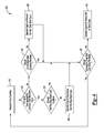
FIG. 4 shows an exemplary pump response method utilized by the vehicle of FIG. 1.
DETAILED DESCRIPTION
This disclosure relates to monitoring and reacting to conditions of a pump within a vehicle. Some pump conditions reflect a potentially recoverable fault associated with the pump. In response to such a pump condition, the vehicle may discontinue or prevent a stop-start cycle within a drive cycle, but permit a subsequent stop-start cycle later in the drive cycle.
Referring to FIG. 1, an example vehicle 10 includes an engine 14, a pump 18, and a vehicle controller 22. The example vehicle 10 is a stop-start vehicle that incorporates stop-start system. At least the engine 14, pump 18, and controller 22 provide portions of the stop-start system.
The engine 14 can be employed as a drive source for wheels 24 of the vehicle 10. The vehicle 10 can be a rear wheel drive, front wheel drive, or all-wheel drive vehicle.
In one embodiment, the engine 14 is an internal combustion engine. Although not shown, the vehicle 10 could include additional propulsion devices capable of driving wheels of the vehicle 10, such as an electric machine (i.e., a motor, generator, or combined motor generator), within hybrid vehicle embodiments. That is the vehicle 10 could be an electrified vehicle, or another type of vehicle incorporating a stop-start system. In one specific example, the vehicle 10 is a micro-hybrid vehicle. Other examples can include mild-hybrids and rolling stop-start vehicles.
The example pump 18 is an electric transmission pump (epump) that maintains pressure of a fluid within the vehicle 10. The fluid can circulate through portions of the engine 14 and through other areas of the vehicle 10, such as through a transmission associated with the engine 14. The pump 18 can circulate the fluid in some examples in addition to maintaining fluid pressure.
The pump 18 is typically used to maintain pressure on the fluid and circulate the fluid when the engine 14 is not able to do so, such as when the engine 14 is commanded off during a stop-start cycle.
The controller 22 is operably linked to the engine 14 and the pump 18. The controller 22 can cause the engine 14 to stop operating or can cause the engine 14 to start operating.
While schematically illustrated as a single controller, the controller 22 may be part of a larger control system within the vehicle 10 and may be controlled by various other controllers throughout the vehicle 10, such as a vehicle system controller (VSC) that includes a powertrain control unit, a transmission control unit, an engine control unit, etc. It should therefore be understood that the controller 22 can be referred to as a controller that controls, such as by a plurality of interrelated algorithms, various functions of the vehicle 10. Functions controlled by the controller 22 include stopping and starting the engine 14, and stopping and starting the pump 18. In one embodiment, the various controllers that make up the VSC may communicate with each other using a common bus protocol (e.g., CAN).
In an exemplary start-stop cycle of the vehicle 10, the engine 14 is automatically shut down during times when the vehicle 10 is not moving or does not require substantial torque from the engine 14. The engine 14 is then restarted as necessary when the vehicle 10 begins to move or is required to operate to drive accessories of the engine 14. The vehicle 10 including the stop-start functionality can shut down and restart the engine 14 to reduce the amount of time the engine 14 spends idling, which can desirably reduce fuel consumption and emissions. Automatically shutting down the engine 14 can be advantageous for vehicles that spend significant amounts of time waiting at traffic lights or frequently operate in stop-and-go traffic.
In some examples, the vehicle 10 may enter an auto-stop mode (i.e., the engine 14 is auto stopped when certain vehicle propulsion conditions are met), such as when the drive has applied the brakes and the speed of the vehicle 10 is below a predetermined speed threshold. Once the driver indicates a request for vehicle propulsion (e.g., by releasing a brake pedal), the controller 22 automatically commands a restart of the engine 14.
When the engine 14 is shut down, the pump 18 operates to maintain pressure and circulate fluid. The pump 18 is typically commanded on just before the engine 14 is shut down at the start of a stop-start cycle. Starting the pump 18 just prior to the stop-start cycle ensures that fluid pressure and circulation is sufficient during the stop-start cycle.
In the past, even if the controller 22 would detect an undesirable condition of the pump 18, the controller 22 would still permit the engine 14 to shut down and begin the stop-start cycle. The undesirable condition associated with the pump 18 would then result in insufficient fluid pressure, fluid circulation, or both. Insufficient fluid pressure or circulation can cause undesirable driveline clunk when the engine 14 is restarted at the conclusion of the stop-start cycle. The exemplary embodiment, among other things, addresses these issues by preventing a stop-start cycle of the engine 14 if certain conditions are detected from the pump 18.
Referring now to FIG. 2 with continued reference to FIG. 1, the example pump 18 is an auxiliary electric transmission fluid pump. The pump 18 can be referred to as an epump. The pump 18 includes a motor 26 that is powered to drive the pump 18. When powered, the pump 18 can maintain fluid pressure and circulate fluid within the engine 14, a transmission associated with the engine 14, or both.
The example vehicle controller 22 includes a processor 30 and a memory portion 34. The processor 30 can be programmed to execute a program stored in the memory portion 34. The program can be stored in the memory portion 34 as software code. The program stored in the memory portion 34 can include one or more additional or separate programs, each of which includes an ordered listing of executable instructions for implementing logical functions associated with, for example, controlling stop-start cycles of the engine 14 in response to conditions received from the pump 18.
Referring now to FIG. 3 with continuing reference to FIGS. 1 and 2, a graph 50 shows speeds of the vehicle 10 during a selected portion a drive cycle for the vehicle 10. Further, a graph 60 shows corresponding speeds of the engine 14, and a graph 70 shows corresponding speeds of the pump 18 during the selected portion of the drive cycle.
Generally, the drive cycle begins when a user powers on the vehicle 10 from a shutdown condition. The drive cycle continues until the user shuts down the vehicle 10 when, for example, the user has reached a desired destination. In some examples, the vehicle 10 is keyed on to start a drive cycle and keyed off to conclude a drive cycle. For purposes of this disclosure, a drive cycle should not be interpreted as referring to the general changes in operating states of the vehicle 10 as the vehicle 10 is driven. For example, when the vehicle 10 shuts down the engine 14 to begin a stop-start cycle, this is not a conclusion of a drive cycle unless the vehicle 10 is keyed off.
The selected portion of the drive cycle includes two separate stop-start cycles. The first stop-start cycle begins at time T2 and ends at time T3. The second stop-start cycle begins at time T5 and ends at time T6. The engine 14 is commanded off and is not operating during the two stop-start cycles. The engine 14 is commanded off at the time T2 to begin the first stop-start cycle and commanded on at time T3 to end the first stop-start cycle. The engine 14 is commanded off at the time T5 to begin the second stop-start cycle and commanded on at time T6 to end the second stop-start cycle.
The pump 18 is commanded on and starts increasing in speed at the time T1 to support the first stop-start cycle. The pump 18 is then commanded off at the time T3. The pump 18 is commanded on and starts increasing in speed at the time T4 to support the second stop-start cycle. The pump 18 is then commanded off at the time T6. The times from T1 to T2 and from T4 to T5 can be considered prestaging times for the respective stop-start cycles. In some examples, the pump 18 is commanded on 3 milliseconds prior to the start of a stop-start cycles.
The vehicle controller 22 continually monitors the pump 18 throughout the drive cycle. The pump 18 can convey specific pump conditions to the controller 22 via electronic communications. In some examples, the pump 18 may send a signal to the controller 22. The signal changes to represent a particular pump condition.
The signal sent to the controller 22 from the pump 18 can be a pulse width modulated signal. In such an example, the pump 18 may vary a duty cycle of the pulse with modulated signal to represent a particular pump condition.
Referring now to FIG. 4 with continuing reference to FIG. 2, an exemplary pump response method 100 begin at a step 110 where a pump condition is received at the controller 22. The method 100 then moves to step 120, which assesses whether the engine 14 is commanded off during a first stop-start cycle. The engine 14 is commanded off during a first stop-start cycle, in this example, from time T2 to T3. If the assessment determines that the engine 14 is off, the method 100 moves to a step 130. If the engine 14 is not commanded off, and thus operating, the method moves to a step 140.
At the step 130, the method 100 calculates whether the first stop-start cycle should continue. If yes, the method 100 continues to a step 150. If no, the method 100 continues to a step 160, which commands on the engine 14 so that the engine 14 operates and discontinues the first stop-start cycle. Assessing whether the first start-stop cycle should continue depends, at least in part, on the pump condition received at the step 110. Some pump conditions necessitate discontinuing a stop-start cycle, while others can permit the stop-start cycle to continue.
At the step 150, the method 100 calculates whether subsequent stop-start cycles should be permitted. If yes, the method 100 returns to the step 110. If no, the method 100 moves to a step 170, which causes the engine 14 to operate for a remainder of the drive cycle. Assessing whether the subsequent start-stop cycles should be permitted depends, at least in part, on the pump condition received at the step 110. Some pump conditions necessitate preventing stop-start cycles for a remainder of the drive cycle, while others, such as those indicating recoverable pump faults, can permit subsequent stop-start cycles to permit recovery from those faults.
Returning to the step 140, the engine 14 is commanded on and operating. At the step 140, the method 100 calculates whether a first stop-start cycle should be permitted. If yes, the method 100 moves to the step 150. If no, the method 100 progresses to a step 180, which continues operating the engine 14 to prevent the first stop-start cycle. Assessing whether the first start-stop cycle should be permitted depends, at least in part, on the pump condition received at the step 110. Some pump conditions necessitate preventing any stop-start cycles, while others, such as those indicating recoverable pump faults, can permit the first stop-start cycle and then prevent subsequent stop-start cycles if the pump has not recovered.
Pump conditions received by the controller 22 can represent a variety of conditions related to the pump 18 and operation of the pump 18. Some pump conditions indicate that the pump 18 is functioning properly. Others can represent pump faults that are potentially recoverable. That is, the pump 18 may self-correct during operation to recover from the pump fault. Other pump faults are not recoverable. Several example pump conditions are described below.
In one example, the controller 22 receives a pump condition indicating that the pump 18 has an undercurrent/load, but the speed of the motor 26 correct. This pump condition can mean that a current at the pump 18 is less than a threshold percent of a normal current (e.g., 10% of normal operating range of current at actual and normal speed, speed +/− 10%). If this pump condition is received outside of a stop-start cycle of the engine 14, the controller 22 may prevent an upcoming stop-start cycle of the engine 14 by continuing to keep the engine 14 operating. Since the engine 14 continues to operate, driveline clunk, or other undesirable factors due to restarting the engine 14 are avoided. If this pump condition is detected when the engine 14 is shut down during a stop-start cycle, the controller 22 may permit the stop-start cycle to continue and the stop-start cycle is not interrupted. This pump condition is considered a recoverable fault. That is, if the condition is detected after the engine 14 is shut down, the condition may self-correct during a subsequent start-stop cycle later in the drive cycle where repriming is most likely to occur. After the condition is self-corrected, the controller 22 would no longer detect the condition.
In another example, the controller 22 receives a pump condition indicating that the pump 18 has an overcurrent/load, but the speed of the motor 26 is correct. This pump condition can mean that a current at the pump 18 is greater than a threshold percent of a normal current (e.g., 10% of normal operating range of current at actual and normal speed, speed +/− 10%). In response to this pump condition, the controller 22 may shut down the motor 26 after a threshold delay, say ten seconds. Shutting down the motor 26 can protect the motor 26. In response to this pump condition, the controller 22 can further prevent any upcoming stop-start cycle of the engine 14 by continuing to keep the engine 14 operating for a remainder of the drive cycle. If this pump condition is detected when the engine 14 is shut down during a stop-start cycle, the controller 22 starts the engine 14 to discontinue the stop-start cycle. Restarting the engine 14 can prevent damage to the pump 18. This pump condition is generally considered a non-recoverable fault.
In another example, the controller 22 receives a pump condition indicating that a temperature associated with the pump 18 exceeds a threshold temperature. In response to this pump condition, the controller 22 may shut down the motor 26. The controller 22 could, for example, shut down the motor 26 if the pump temperature exceeds another threshold motor shutdown temperature. In response to this pump condition, the controller 22 can delay an upcoming stop-start cycle. This pump condition is, in some examples, a result of a heat source external to the pump 18. The heat source may lose heat causing a drop in the temperature associated with the pump 18 below the threshold temperature. The pump condition is thus potentially a recoverable fault. Notably, since the stop-start cycle is delayed or avoided until the temperature recovers and falls below the threshold temperature, an operator of the vehicle 10 may not perceive this pump condition, which can be desirable.
In another example, the controller 22 receives a pump condition indicating that a speed of the pump 18 is less than a threshold speed (e.g., a speed of 100 rpm after 300 msec of the speed being commanded). This pump condition can indicate that the pump 18 is stalled or otherwise unable to reach a targeted speed. In response to this pump condition, the controller 22 may shut down the motor 26 after a threshold delay, say 2000 milliseconds. In response to this pump condition, the controller 22 can further prevent any upcoming stop-start cycle of the engine 14 by continuing to keep the engine 14 operating for a remainder of the drive cycle. If this pump condition is detected when the engine 14 is shut down during a stop-start cycle, the controller 22 allows the stop-cycle to continue because restarting the engine while the condition is present may result in drive-line clunk. Since this pump condition is not likely to result in damage to the pump, the current stop-start cycle is allowed to continue in hopes that the fault will recover.
This pump condition is generally considered a non-recoverable fault. The controller 22 may permit one stop-start cycle, but then prevent any other stop-start cycles for a remainder of the drive cycle in response to this pump condition. Alternatively, the controller 22 may prevent the engine 14 from autostopping for the entire drive cycle in response to this condition.
In another example, the controller 22 receives a pump condition indicating that the pump 18 has a correct current and speed condition. The pump condition can reflect the pump 18 operating current to be within 10% of a normal operating range and an actual speed being within 10% of a commanded speed.
In another example, the controller 22 receives a pump condition indicating that the pump 18 is running over speed, but with a correct current. This pump condition can mean that a speed of the pump 18 is greater than a threshold percent of a commanded speed (e.g., 110% of a commanded speed). In response to this pump condition, the controller 22 may shut down the motor 26 after a threshold delay, say 15 seconds. If this pump condition is received, the controller 22 does not prevent or discontinue a stop-start cycle of the engine 14. This pump condition typically does not cause durability issues or functional issues perceived by a driver.
In another example, the controller 22 receives a pump condition indicating that the pump 18 is running under speed, but with correct current. The pump condition can mean that a speed of the pump 18 is less than a threshold percent of a commanded speed (e.g., 90% of a commanded speed. The operating current in this pump condition can be within 10% of a normal operating range. In response to this pump condition, the controller 22 can prevent any upcoming stop-start cycle of the engine 14 by continuing to keep the engine 14 operating for a remainder of the drive cycle. The pump condition can undesirably result in driveline clunk or other undesirable characteristics. Thus, avoiding upcoming stop-start cycles for the remainder of the drive cycle may be desirable. If this pump condition is detected when the engine 14 is shut down during a stop-start cycle, the controller 22 does not, in response to this pump condition, restart the engine 14 to discontinue the stop-start cycle. If detected when the engine 14 is shut down during a stop-cycle, restart is going to occur anyway, so permitting the stop-start cycle to continue may provide the pump 18 with time to recover from this pump condition.
In another example, the controller 22 receives a pump condition indicating that the pump 18 has a current and speed outside of a threshold range condition. This pump condition can be in response to a measured speed differing by more than 10% from a commanded speed, and a measured current differing by more than 10% from a current corresponding to the commanded speed. In response to this pump condition, the controller 22 may shut down the motor 26 after a threshold delay. The delay can be calibrated to protect the motor. In response to this pump condition, the controller 22 can avoid upcoming stop-start cycles for the remainder of the drive cycle, and can further restart the engine 14 to discontinue a stop-start cycle if the pump condition is received during a stop-start cycle. This pump condition can indicate that damage to the pump 18 can occur, thus operating the engine 14 so that the pump 18 is not required to operate can be desirable.
In another example, the controller 22 receives a pump condition indicating that the pump 18 has and a speed disabled condition where no command signal is received at the pump 18. The pump condition can indicate that the controller 22 is detecting no command signal sent to the controller 22 (e.g., powertrain control module) to the pump 18. In response to this pump condition, the controller 22 may shut down the motor 26 after a threshold delay, say 2000 milliseconds. This pump condition is generally considered a recoverable fault. Thus, in response to this pump condition, the controller 22 can start the engine 14 or continue to operate the engine 14 to discontinue a stop-start cycle and avoid upcoming stop-start cycles. The controller 22 continues to keep the engine 14 operating through the drive-cycle until the pump condition changes indicating that a command signal is received.
In another example, the controller 22 receives a pump condition indicating that the signal sent from the pump 18 to the controller 22 has a frequency that is outside of a set range. This pump condition is generally considered a recoverable fault. Thus, in response to this pump condition, the controller 22 can start the engine 14 or continue to operate the engine 14 to discontinue a stop-start cycle and avoid upcoming stop-start cycles. The controller 22 continues to keep the engine 14 operating through the drive-cycle until the pump condition changes indicating that a signal sent from the pump 18 to the controller 22 has returned to be within the set range.
In another example, the signal sent from the pump 18 to the controller 22 is a pulse width modulated signal having a duty cycle that is varied to represent particular pump conditions. The controller 22 can receive a pump condition indicating that the signal has a duty cycle that is outside of a set range. This pump condition is generally considered a recoverable fault. Thus, in response to this pump condition, the controller 22 can start the engine 14 or continue to operate the engine 14 to discontinue a stop-start cycle and avoid upcoming stop-start cycles. The controller 22 continues to keep the engine 14 operating through the drive-cycle until the pump condition changes indicating that a signal sent from the pump 18 to the controller 22 has a duty cycle falling within the set range such that the controller 22 can receive other pump conditions.
The preceding description is exemplary rather than limiting in nature. Variations and modifications to the disclosed examples may become apparent to those skilled in the art that do not necessarily depart from the essence of this disclosure. Thus, the scope of legal protection given to this disclosure can only be determined by studying the following claims.

Claims (20)

What is claimed is:
1. A pump condition response method, comprising:
in response to a pump condition, operating an engine to discontinue or prevent a first stop-start cycle during a drive cycle, and then permitting a second stop-start cycle during the drive cycle.
2. The method of claim 1, wherein the pump condition is a recoverable fault.
3. The method of claim 1, wherein the pump condition is a first pump condition, and further comprising, in response to a second pump condition, operating the engine for a remainder of the drive cycle to prevent any stop-start cycle during the drive cycle.
4. The method of claim 3, wherein the second pump condition is non-recoverable fault.
5. The method of claim 1, wherein the first stop-start cycle and the second stop-start cycle are within the same drive cycle.
6. The method of claim 1, wherein the operating comprises idling.
7. The method of claim 1, wherein the pump condition is a recoverable fault and is received when the pump is commanded on and the engine is commanded off, and the method further comprises starting the engine and then receiving an additional pump condition later in the drive cycle, the method permitting the second stop-start cycle if the additional pump condition indicates that the pump has recovered from the recoverable fault.
8. The method of claim 1, wherein the pump condition is first pump condition, and further comprising, in response to a second pump condition, preventing any stop-start cycle during a remainder of the drive cycle.
9. An electrified vehicle assembly, comprising:
a pump;
an engine; and
a vehicle controller configured to discontinue or prevent a first stop-start cycle by commanding the engine on in response to a pump condition received during a drive cycle, the vehicle controller further configured to permit a second stop-start cycle of the engine later in the drive cycle.
10. The assembly of claim 9, wherein the pump condition is a recoverable fault.
11. The assembly of claim 9, wherein the pump condition is a first pump condition, and the vehicle controller is further configured to command the engine to operate for a remainder of the drive cycle in response to a second pump condition.
12. The assembly of claim 11, wherein the second pump condition is a non-recoverable fault.
13. The assembly of claim 9, wherein the first stop-start cycle and the second stop-start cycle are within the same drive cycle.
14. The assembly of claim 9, wherein the pump condition is the recoverable fault and is received when the pump is commanded on and the engine is commanded off, and the controller is further configured to command the engine on and to permit the second stop-start cycle if an additional pump condition received later in the drive cycle indicates that the pump has recovered from the recoverable fault.
15. The assembly of claim 9, wherein the pump condition is first pump condition, and further comprising, in response to a second pump condition, preventing any stop-start cycle during a remainder of the drive cycle.
16. The assembly of claim 9, wherein the vehicle controller comprises a powertrain control module.
17. The assembly of claim 9, wherein the engine, the pump, and the vehicle controller are portions of a stop-start vehicle.
18. The assembly of claim 9, wherein the engine, the pump, and the vehicle controller are portions of an electrified vehicle.
19. The method of claim 1, further comprising communicating fluid through the engine using a pump, the pump condition a condition of the pump that communicates fluid through the engine.
20. The assembly of claim 9, wherein the pump operates to influence a pressure of a fluid within the engine.
US15/046,756 2016-02-18 2016-02-18 Vehicle pump condition response method and assembly Active US9821799B2 (en)

Priority Applications (3)

Application Number Priority Date Filing Date Title
US15/046,756 US9821799B2 (en) 2016-02-18 2016-02-18 Vehicle pump condition response method and assembly
CN201710076877.2A CN107089232B (en) 2016-02-18 2017-02-13 Vehicle pump condition response method and assembly
DE102017103218.5A DE102017103218B4 (en) 2016-02-18 2017-02-16 VEHICLE PUMP CONDITION REACTION METHOD AND ARRANGEMENT

Applications Claiming Priority (1)

Application Number Priority Date Filing Date Title
US15/046,756 US9821799B2 (en) 2016-02-18 2016-02-18 Vehicle pump condition response method and assembly

Publications (2)

Publication Number Publication Date
US20170240166A1 US20170240166A1 (en) 2017-08-24
US9821799B2 true US9821799B2 (en) 2017-11-21

Family

ID=59522290

Family Applications (1)

Application Number Title Priority Date Filing Date
US15/046,756 Active US9821799B2 (en) 2016-02-18 2016-02-18 Vehicle pump condition response method and assembly

Country Status (3)

Country Link
US (1) US9821799B2 (en)
CN (1) CN107089232B (en)
DE (1) DE102017103218B4 (en)

Cited By (1)

* Cited by examiner, † Cited by third party
Publication number Priority date Publication date Assignee Title
US11402017B1 (en) 2021-04-16 2022-08-02 Ford Global Technologies, Llc Systems and methods for operating transmission with auxiliary pump in power-limiting mode

Citations (18)

* Cited by examiner, † Cited by third party
Publication number Priority date Publication date Assignee Title
US6730000B1 (en) * 2002-12-09 2004-05-04 Daimlerchrysler Corporation Interactive process during engine idle stop mode
US20040144107A1 (en) * 2003-01-27 2004-07-29 Matthew Breton HVAC controls for a vehicle with start-stop engine operation
US20040153236A1 (en) * 2003-01-21 2004-08-05 Yoshiki Itoh Automatic stop/start controller for an engine
US20060137643A1 (en) * 2004-12-28 2006-06-29 Marleen Thompson Battery voltage threshold adjustment for automatic start and stop system
US20100217470A1 (en) * 2009-02-25 2010-08-26 Gm Global Technology Operations, Inc. Auxiliary pump diagnostic systems and methods
US20110077830A1 (en) * 2009-09-28 2011-03-31 Gm Global Technology Operations, Inc. Method and apparatus for neutral idle clutch control in a vehicle having an engine start-stop powertrain
US20110166727A1 (en) * 2010-08-30 2011-07-07 Ford Global Technologies, Llc Method And System For Controlling Operation Of An Electric Oil Pump In A Hybrid Electric Vehicle (HEV)
US8068966B2 (en) 2007-11-03 2011-11-29 GM Global Technology Operations LLC Method for monitoring an auxiliary pump for a hybrid powertrain
US8219291B2 (en) 2010-08-30 2012-07-10 GM Global Technology Operations LLC Method of controlling a vehicle during an auxiliary pump failure
US8608620B2 (en) 2010-12-08 2013-12-17 Hyundai Motor Company Control method of assist pump for automatic transmission of vehicle provided with ISG system
US8616323B1 (en) * 2009-03-11 2013-12-31 Echogen Power Systems Hybrid power systems
US20140309910A1 (en) * 2013-04-10 2014-10-16 Ford Global Technologies, Llc Method of controlling an engine of a motor vehicle
US8892339B2 (en) * 2010-06-01 2014-11-18 GM Global Technology Operations LLC Transmission load predicting system for a stop-start system and a hybrid electric vehicle
US9046047B2 (en) 2013-03-11 2015-06-02 Ford Global Technologies, Llc Control for stop/start vehicle when approaching controlled intersections
US20150159576A1 (en) 2013-12-06 2015-06-11 Ford Global Technologies, Llc Adaptive learning of duty cycle for a high pressure fuel pump
US20150219056A1 (en) * 2014-02-06 2015-08-06 Ford Global Technologies, Llc Combined coolant and transmission pump motor drive for stop-start vehicle
DE102015103270A1 (en) 2014-03-18 2015-09-24 Ford Global Technologies, Llc EXPAND RECUPERATION BRAKING IN HYBRID ELECTRIC VEHICLES
US20160281630A1 (en) * 2015-03-25 2016-09-29 Ford Global Technologies, Llc Method for mitigating cavitation

Family Cites Families (2)

* Cited by examiner, † Cited by third party
Publication number Priority date Publication date Assignee Title
DE102007001499B4 (en) * 2007-01-10 2022-09-15 Zf Friedrichshafen Ag Method for determining an operating state of a transmission device
DE102012201436A1 (en) * 2012-02-01 2013-08-01 Robert Bosch Gmbh A brake operation detecting apparatus and method for detecting an operation of a brake operating member of a brake system

Patent Citations (18)

* Cited by examiner, † Cited by third party
Publication number Priority date Publication date Assignee Title
US6730000B1 (en) * 2002-12-09 2004-05-04 Daimlerchrysler Corporation Interactive process during engine idle stop mode
US20040153236A1 (en) * 2003-01-21 2004-08-05 Yoshiki Itoh Automatic stop/start controller for an engine
US20040144107A1 (en) * 2003-01-27 2004-07-29 Matthew Breton HVAC controls for a vehicle with start-stop engine operation
US20060137643A1 (en) * 2004-12-28 2006-06-29 Marleen Thompson Battery voltage threshold adjustment for automatic start and stop system
US8068966B2 (en) 2007-11-03 2011-11-29 GM Global Technology Operations LLC Method for monitoring an auxiliary pump for a hybrid powertrain
US20100217470A1 (en) * 2009-02-25 2010-08-26 Gm Global Technology Operations, Inc. Auxiliary pump diagnostic systems and methods
US8616323B1 (en) * 2009-03-11 2013-12-31 Echogen Power Systems Hybrid power systems
US20110077830A1 (en) * 2009-09-28 2011-03-31 Gm Global Technology Operations, Inc. Method and apparatus for neutral idle clutch control in a vehicle having an engine start-stop powertrain
US8892339B2 (en) * 2010-06-01 2014-11-18 GM Global Technology Operations LLC Transmission load predicting system for a stop-start system and a hybrid electric vehicle
US8219291B2 (en) 2010-08-30 2012-07-10 GM Global Technology Operations LLC Method of controlling a vehicle during an auxiliary pump failure
US20110166727A1 (en) * 2010-08-30 2011-07-07 Ford Global Technologies, Llc Method And System For Controlling Operation Of An Electric Oil Pump In A Hybrid Electric Vehicle (HEV)
US8608620B2 (en) 2010-12-08 2013-12-17 Hyundai Motor Company Control method of assist pump for automatic transmission of vehicle provided with ISG system
US9046047B2 (en) 2013-03-11 2015-06-02 Ford Global Technologies, Llc Control for stop/start vehicle when approaching controlled intersections
US20140309910A1 (en) * 2013-04-10 2014-10-16 Ford Global Technologies, Llc Method of controlling an engine of a motor vehicle
US20150159576A1 (en) 2013-12-06 2015-06-11 Ford Global Technologies, Llc Adaptive learning of duty cycle for a high pressure fuel pump
US20150219056A1 (en) * 2014-02-06 2015-08-06 Ford Global Technologies, Llc Combined coolant and transmission pump motor drive for stop-start vehicle
DE102015103270A1 (en) 2014-03-18 2015-09-24 Ford Global Technologies, Llc EXPAND RECUPERATION BRAKING IN HYBRID ELECTRIC VEHICLES
US20160281630A1 (en) * 2015-03-25 2016-09-29 Ford Global Technologies, Llc Method for mitigating cavitation

Non-Patent Citations (1)

* Cited by examiner, † Cited by third party
Title
Cord Concentrates on Control Strategies for Low-Cost Start-Stop System for Fusion, Jul. 19, 2012, Retrieved from: http://www.greencarcongress.om/2012/07/ford-20120719.html.

Cited By (1)

* Cited by examiner, † Cited by third party
Publication number Priority date Publication date Assignee Title
US11402017B1 (en) 2021-04-16 2022-08-02 Ford Global Technologies, Llc Systems and methods for operating transmission with auxiliary pump in power-limiting mode

Also Published As

Publication number Publication date
CN107089232A (en) 2017-08-25
DE102017103218B4 (en) 2025-07-03
US20170240166A1 (en) 2017-08-24
DE102017103218A1 (en) 2017-08-24
CN107089232B (en) 2021-11-30

Similar Documents

Publication Publication Date Title
KR101199058B1 (en) Idle stop and go system and method for controlling thereof
JP6097023B2 (en) Hybrid vehicle engine stop state determination system and method
JP5286425B2 (en) Control apparatus and method for vehicle
US20140024492A1 (en) Hybrid electric vehicle controller and method of controlling a hybrid electric vehicle
JP2004003434A (en) Engine-starting system
JP6123783B2 (en) Negative pressure abnormality detection device and control device for internal combustion engine
EP3499010B1 (en) Method and device for controlling vehicle including idle stop and go function
JP5382260B1 (en) ENGINE RESTART CONTROL DEVICE, VEHICLE, AND VEHICLE CONTROL METHOD
JP4376749B2 (en) Control device for internal combustion engine and automobile equipped with the same
US9599088B2 (en) System for cranking internal combustion engine by engagement of pinion with ring gear
US9821799B2 (en) Vehicle pump condition response method and assembly
WO2017002228A1 (en) Vehicle control device and vehicle control method
KR20090040930A (en) Engine restart control method in case of electric oil pump failure of hybrid vehicle
JP2004092453A (en) Vehicle control device
JP2003232238A (en) Vehicle engine control device
US20150292465A1 (en) Vehicle starter activation counter
JP2004308511A (en) Idle stop vehicle control device
KR100844669B1 (en) Engine auto start stop control system and method for hybrid vehicle
EP2743480B1 (en) Vehicle control apparatus, vehicle, and vehicle control method
JP7102074B2 (en) Vehicle control device
CN108869065B (en) Control device and control method for vehicle
US20250242795A1 (en) System and method for engine stall recovery and restart for hybrid electric vehicle
JP2017008738A (en) Engine starting device
JP6007816B2 (en) Vehicle control device
JPH08164775A (en) Control unit of driving gear fo vehicle

Legal Events

Date Code Title Description
AS Assignment

Owner name: FORD GLOBAL TECHNOLOGIES, LLC, MICHIGAN

Free format text: ASSIGNMENT OF ASSIGNORS INTEREST;ASSIGNORS:KHAFAGY, HAFIZ SHAFEEK;PATTERSON, WILLIAM REY, JR.;LINT, BRANDON DAVID;AND OTHERS;REEL/FRAME:037764/0934

Effective date: 20160217

STCF Information on status: patent grant

Free format text: PATENTED CASE

CC Certificate of correction
MAFP Maintenance fee payment

Free format text: PAYMENT OF MAINTENANCE FEE, 4TH YEAR, LARGE ENTITY (ORIGINAL EVENT CODE: M1551); ENTITY STATUS OF PATENT OWNER: LARGE ENTITY

Year of fee payment: 4

MAFP Maintenance fee payment

Free format text: PAYMENT OF MAINTENANCE FEE, 8TH YEAR, LARGE ENTITY (ORIGINAL EVENT CODE: M1552); ENTITY STATUS OF PATENT OWNER: LARGE ENTITY

Year of fee payment: 8