US9818746B2 - Structure and method to suppress work function effect by patterning boundary proximity in replacement metal gate - Google Patents
Structure and method to suppress work function effect by patterning boundary proximity in replacement metal gate Download PDFInfo
- Publication number
- US9818746B2 US9818746B2 US14/994,650 US201614994650A US9818746B2 US 9818746 B2 US9818746 B2 US 9818746B2 US 201614994650 A US201614994650 A US 201614994650A US 9818746 B2 US9818746 B2 US 9818746B2
- Authority
- US
- United States
- Prior art keywords
- transistor
- metal gate
- nfet
- pfet
- dielectric
- Prior art date
- Legal status (The legal status is an assumption and is not a legal conclusion. Google has not performed a legal analysis and makes no representation as to the accuracy of the status listed.)
- Expired - Fee Related
Links
Images


Classifications
-
- H—ELECTRICITY
- H10—SEMICONDUCTOR DEVICES; ELECTRIC SOLID-STATE DEVICES NOT OTHERWISE PROVIDED FOR
- H10D—INORGANIC ELECTRIC SEMICONDUCTOR DEVICES
- H10D84/00—Integrated devices formed in or on semiconductor substrates that comprise only semiconducting layers, e.g. on Si wafers or on GaAs-on-Si wafers
- H10D84/80—Integrated devices formed in or on semiconductor substrates that comprise only semiconducting layers, e.g. on Si wafers or on GaAs-on-Si wafers characterised by the integration of at least one component covered by groups H10D12/00 or H10D30/00, e.g. integration of IGFETs
- H10D84/82—Integrated devices formed in or on semiconductor substrates that comprise only semiconducting layers, e.g. on Si wafers or on GaAs-on-Si wafers characterised by the integration of at least one component covered by groups H10D12/00 or H10D30/00, e.g. integration of IGFETs of only field-effect components
- H10D84/83—Integrated devices formed in or on semiconductor substrates that comprise only semiconducting layers, e.g. on Si wafers or on GaAs-on-Si wafers characterised by the integration of at least one component covered by groups H10D12/00 or H10D30/00, e.g. integration of IGFETs of only field-effect components of only insulated-gate FETs [IGFET]
- H10D84/85—Complementary IGFETs, e.g. CMOS
-
- H01L27/092—
-
- H01L21/823807—
-
- H01L21/823828—
-
- H01L29/42372—
-
- H01L29/4958—
-
- H01L29/4966—
-
- H01L29/517—
-
- H01L29/66545—
-
- H—ELECTRICITY
- H10—SEMICONDUCTOR DEVICES; ELECTRIC SOLID-STATE DEVICES NOT OTHERWISE PROVIDED FOR
- H10D—INORGANIC ELECTRIC SEMICONDUCTOR DEVICES
- H10D64/00—Electrodes of devices having potential barriers
- H10D64/20—Electrodes characterised by their shapes, relative sizes or dispositions
- H10D64/27—Electrodes not carrying the current to be rectified, amplified, oscillated or switched, e.g. gates
- H10D64/311—Gate electrodes for field-effect devices
- H10D64/411—Gate electrodes for field-effect devices for FETs
- H10D64/511—Gate electrodes for field-effect devices for FETs for IGFETs
- H10D64/517—Gate electrodes for field-effect devices for FETs for IGFETs characterised by the conducting layers
-
- H—ELECTRICITY
- H10—SEMICONDUCTOR DEVICES; ELECTRIC SOLID-STATE DEVICES NOT OTHERWISE PROVIDED FOR
- H10D—INORGANIC ELECTRIC SEMICONDUCTOR DEVICES
- H10D64/00—Electrodes of devices having potential barriers
- H10D64/60—Electrodes characterised by their materials
- H10D64/66—Electrodes having a conductor capacitively coupled to a semiconductor by an insulator, e.g. MIS electrodes
- H10D64/665—Electrodes having a conductor capacitively coupled to a semiconductor by an insulator, e.g. MIS electrodes the conductor comprising a layer of elemental metal contacting the insulator, e.g. tungsten or molybdenum
- H10D64/666—Electrodes having a conductor capacitively coupled to a semiconductor by an insulator, e.g. MIS electrodes the conductor comprising a layer of elemental metal contacting the insulator, e.g. tungsten or molybdenum the conductor further comprising additional layers
-
- H—ELECTRICITY
- H10—SEMICONDUCTOR DEVICES; ELECTRIC SOLID-STATE DEVICES NOT OTHERWISE PROVIDED FOR
- H10D—INORGANIC ELECTRIC SEMICONDUCTOR DEVICES
- H10D84/00—Integrated devices formed in or on semiconductor substrates that comprise only semiconducting layers, e.g. on Si wafers or on GaAs-on-Si wafers
- H10D84/01—Manufacture or treatment
- H10D84/0123—Integrating together multiple components covered by H10D12/00 or H10D30/00, e.g. integrating multiple IGBTs
- H10D84/0126—Integrating together multiple components covered by H10D12/00 or H10D30/00, e.g. integrating multiple IGBTs the components including insulated gates, e.g. IGFETs
- H10D84/0165—Integrating together multiple components covered by H10D12/00 or H10D30/00, e.g. integrating multiple IGBTs the components including insulated gates, e.g. IGFETs the components including complementary IGFETs, e.g. CMOS devices
- H10D84/0167—Manufacturing their channels
-
- H—ELECTRICITY
- H10—SEMICONDUCTOR DEVICES; ELECTRIC SOLID-STATE DEVICES NOT OTHERWISE PROVIDED FOR
- H10D—INORGANIC ELECTRIC SEMICONDUCTOR DEVICES
- H10D84/00—Integrated devices formed in or on semiconductor substrates that comprise only semiconducting layers, e.g. on Si wafers or on GaAs-on-Si wafers
- H10D84/01—Manufacture or treatment
- H10D84/0123—Integrating together multiple components covered by H10D12/00 or H10D30/00, e.g. integrating multiple IGBTs
- H10D84/0126—Integrating together multiple components covered by H10D12/00 or H10D30/00, e.g. integrating multiple IGBTs the components including insulated gates, e.g. IGFETs
- H10D84/0165—Integrating together multiple components covered by H10D12/00 or H10D30/00, e.g. integrating multiple IGBTs the components including insulated gates, e.g. IGFETs the components including complementary IGFETs, e.g. CMOS devices
- H10D84/0172—Manufacturing their gate conductors
- H10D84/0177—Manufacturing their gate conductors the gate conductors having different materials or different implants
-
- H—ELECTRICITY
- H10—SEMICONDUCTOR DEVICES; ELECTRIC SOLID-STATE DEVICES NOT OTHERWISE PROVIDED FOR
- H10D—INORGANIC ELECTRIC SEMICONDUCTOR DEVICES
- H10D84/00—Integrated devices formed in or on semiconductor substrates that comprise only semiconducting layers, e.g. on Si wafers or on GaAs-on-Si wafers
- H10D84/01—Manufacture or treatment
- H10D84/02—Manufacture or treatment characterised by using material-based technologies
- H10D84/03—Manufacture or treatment characterised by using material-based technologies using Group IV technology, e.g. silicon technology or silicon-carbide [SiC] technology
- H10D84/038—Manufacture or treatment characterised by using material-based technologies using Group IV technology, e.g. silicon technology or silicon-carbide [SiC] technology using silicon technology, e.g. SiGe
-
- H—ELECTRICITY
- H10—SEMICONDUCTOR DEVICES; ELECTRIC SOLID-STATE DEVICES NOT OTHERWISE PROVIDED FOR
- H10D—INORGANIC ELECTRIC SEMICONDUCTOR DEVICES
- H10D84/00—Integrated devices formed in or on semiconductor substrates that comprise only semiconducting layers, e.g. on Si wafers or on GaAs-on-Si wafers
- H10D84/80—Integrated devices formed in or on semiconductor substrates that comprise only semiconducting layers, e.g. on Si wafers or on GaAs-on-Si wafers characterised by the integration of at least one component covered by groups H10D12/00 or H10D30/00, e.g. integration of IGFETs
- H10D84/82—Integrated devices formed in or on semiconductor substrates that comprise only semiconducting layers, e.g. on Si wafers or on GaAs-on-Si wafers characterised by the integration of at least one component covered by groups H10D12/00 or H10D30/00, e.g. integration of IGFETs of only field-effect components
- H10D84/83—Integrated devices formed in or on semiconductor substrates that comprise only semiconducting layers, e.g. on Si wafers or on GaAs-on-Si wafers characterised by the integration of at least one component covered by groups H10D12/00 or H10D30/00, e.g. integration of IGFETs of only field-effect components of only insulated-gate FETs [IGFET]
- H10D84/83135—Integrated devices formed in or on semiconductor substrates that comprise only semiconducting layers, e.g. on Si wafers or on GaAs-on-Si wafers characterised by the integration of at least one component covered by groups H10D12/00 or H10D30/00, e.g. integration of IGFETs of only field-effect components of only insulated-gate FETs [IGFET] the IGFETs characterised by having different gate conductor materials or different gate conductor implants
-
- H—ELECTRICITY
- H10—SEMICONDUCTOR DEVICES; ELECTRIC SOLID-STATE DEVICES NOT OTHERWISE PROVIDED FOR
- H10D—INORGANIC ELECTRIC SEMICONDUCTOR DEVICES
- H10D64/00—Electrodes of devices having potential barriers
- H10D64/60—Electrodes characterised by their materials
- H10D64/66—Electrodes having a conductor capacitively coupled to a semiconductor by an insulator, e.g. MIS electrodes
- H10D64/667—Electrodes having a conductor capacitively coupled to a semiconductor by an insulator, e.g. MIS electrodes the conductor comprising a layer of alloy material, compound material or organic material contacting the insulator, e.g. TiN workfunction layers
- H10D64/669—Electrodes having a conductor capacitively coupled to a semiconductor by an insulator, e.g. MIS electrodes the conductor comprising a layer of alloy material, compound material or organic material contacting the insulator, e.g. TiN workfunction layers the conductor further comprising additional layers of alloy material, compound material or organic material, e.g. TaN/TiAlN
-
- H—ELECTRICITY
- H10—SEMICONDUCTOR DEVICES; ELECTRIC SOLID-STATE DEVICES NOT OTHERWISE PROVIDED FOR
- H10D—INORGANIC ELECTRIC SEMICONDUCTOR DEVICES
- H10D64/00—Electrodes of devices having potential barriers
- H10D64/60—Electrodes characterised by their materials
- H10D64/66—Electrodes having a conductor capacitively coupled to a semiconductor by an insulator, e.g. MIS electrodes
- H10D64/68—Electrodes having a conductor capacitively coupled to a semiconductor by an insulator, e.g. MIS electrodes characterised by the insulator, e.g. by the gate insulator
- H10D64/691—Electrodes having a conductor capacitively coupled to a semiconductor by an insulator, e.g. MIS electrodes characterised by the insulator, e.g. by the gate insulator comprising metallic compounds, e.g. metal oxides or metal silicates
Definitions
- the present invention relates to complementary metal oxide semiconductor (CMOS), and more specifically, to replacement metal gate structures and process flows.
- CMOS complementary metal oxide semiconductor
- CMOS is used for constructing integrated circuits.
- CMOS technology is used in microprocessors, microcontrollers, static RAM, and other digital logic circuits.
- CMOS designs may use complementary and symmetrical pairs of p-type and n-type metal oxide semiconductor field effect transistors (MOSFETs) for logic functions.
- MOSFETs metal oxide semiconductor field effect transistors
- the MOSFET is a transistor used for switching electronic signals.
- the MOSFET has a source, a drain, and a metal oxide gate electrode.
- the metal gate is electrically insulated from the main semiconductor n-channel or p-channel by a thin layer of insulating material, for example, silicon dioxide or high dielectric constant (high-k) dielectrics, which makes the input resistance of the MOSFET relatively high.
- the gate voltage controls whether the path from drain to source is an open circuit (“off”) or a resistive path (“on”).
- N-type field effect transistors and p-type field effect transistors (pFET) are two types of complementary MOSFETs.
- the nFET uses electrons as the current carriers and with n-doped source and drain junctions.
- the pFET uses holes as the current carriers and with p-doped source and drain junctions.
- One technique includes using a high-k dielectric material and replacement metal gate scheme.
- a semiconductor device includes a first transistor formed on a substrate, the first transistor including a channel region positioned on the substrate; a second transistor formed on the substrate, the second transistor including a channel region positioned on the substrate; a high-k dielectric layer disposed on the channel region of the first transistor and the channel region of the second transistor; a first transistor metal gate positioned in contact with the high-k dielectric on the first transistor; a second transistor metal gate positioned in contact with the high-k dielectric on the second transistor; an oxygen absorbing barrier disposed in contact with the high-k dielectric between the first transistor and the second transistor; and a conductive electrode material disposed on the first transistor, the second transistor, and the oxygen absorbing barrier.
- a semiconductor device includes an nFET formed on a substrate, the nFET including a channel region positioned on the substrate; a pFET formed on the substrate, the pFET including a channel region positioned on the substrate; a high-k dielectric layer disposed on the channel region of the nFET and the channel region of the pFET; an nFET metal gate positioned in contact with the high-k dielectric on the nFET; a pFET metal gate positioned in contact with the high-k dielectric on the pFET; an oxygen absorbing barrier disposed between the nFET and the pFET and in contact with the high-k dielectric; and a conductive electrode material disposed on the nFET metal gate and the pFET metal gate; wherein the oxygen absorbing barrier extends from a surface of the conductive electrode material to the high-k dielectric between the nFET and the pFET.
- a method of making a semiconductor device includes forming a first transistor channel region and a second transistor channel region on a substrate; disposing a high-k dielectric on the first transistor channel region and the second transistor channel region; forming a first transistor metal gate on the high-k dielectric on the first transistor; forming a second transistor metal gate on the high-k dielectric on the second transistor; depositing an oxygen absorbing barrier between the first transistor and the second transistor, the oxygen absorbing barrier positioned in contact with the high-k dielectric between the first transistor and the second transistor; and depositing a conductive electrode material on the first transistor and the second transistor to form a gate.
- FIG. 1 is a cross-sectional side view of a comparative semiconductor device with an oxygen absorbing transistor stack adjacent to an oxygen providing transistor stack;
- FIG. 2 is a cross-sectional side view of a semiconductor device according to various embodiments, in which an oxygen absorbing barrier is positioned between the oxygen absorbing transistor stack and an oxygen providing transistor stack;
- FIGS. 3-11 illustrate exemplary methods of making semiconductor devices according to an embodiment, in which:
- FIG. 3 is a cross-sectional side view after forming a trench over a first transistor and a second transistor in an inter-layer dielectric (ILD) and depositing a high-k in the trench;
- ILD inter-layer dielectric
- FIG. 4 is a cross-sectional side view after disposing a first transistor gate stack within the trench
- FIG. 5 is a cross-sectional side view after removing the first transistor gate stack from the second transistor
- FIG. 6 is a cross-sectional side view after depositing the second transistor gate stack in the trench
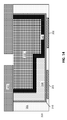
- FIG. 7 is a cross-sectional side view after disposing a sacrificial material in the trench and forming an opening between the first and second transistors;
- FIG. 8 is a cross-sectional side view after removing the sacrificial material to expose the high-k material between the transistors;
- FIG. 9 is a cross-sectional side view after disposing an oxygen absorbing barrier stack between the transistors.
- FIG. 10 is a cross-sectional side view after disposing a conductive electrode material in the trench over the oxygen absorbing barrier stack.
- FIG. 11 is a cross-sectional side view after performing a planarization process
- FIGS. 12-17 illustrate exemplary methods of making semiconductor devices according to another embodiment that follows FIG. 6 , in which:
- FIG. 12 is a cross-sectional side view after disposing a conductive electrode material over the second transistor gate stack of FIG. 6 ;
- FIG. 13 is a cross-sectional side view after performing a planarization process
- FIG. 14 is a cross-sectional side view after disposing a mask on the conductive electrode material and patterning the mask to form an opening between the transistors;
- FIG. 15 is a cross-sectional side view after transferring the pattern from the mask to expose the high-k dielectric between the transistors;
- FIG. 16 is a cross-sectional side view after depositing the oxygen absorbing barrier material in the opening between the transistors.
- FIG. 17 is a cross-sectional side view after performing a planarization process.
- FIG. 18 is a cross-sectional side view of a semiconductor device according to another embodiment.
- threshold voltage of the nFET and pFET can be set by modulating the oxygen vacancy creation in the high-k dielectric by metal gate stack. This can be achieved by using proper work function metals that can either create or preserve oxygen vacancies.
- an nFEt metal gate stack may include an oxygen scavenger/absorber, which creates an oxygen vacancy in the high-k dielectric and defines the nFET threshold voltage (Vt).
- Vt nFET threshold voltage
- the high-k dielectric under the nFET metal gate is thus oxygen depleted.
- the high-k material under pFET metal can be oxygen rich to set the necessary pFET threshold voltage (Vt).
- oxygen may diffuse into the high-k material of the nFET when the nFET and pFET share a metal gate.
- the nFET threshold voltage increases if the pFET metal gate approaches the nFET.
- the pFET threshold voltage increases when the nFET metal gate that includes an oxygen absorber approaches the pFET.
- an nFET 101 and a pFET 102 are formed on a substrate.
- the nFET 101 and pFET 102 include channel regions that are positioned on or within the substrate.
- a high-k dielectric 110 is formed on the channel regions of the nFET 101 and the pFET 102 .
- An nFET metal gate 121 is deposited on the high-k dielectric 110 over the nFET 101 .
- a pFET metal gate 140 is positioned in contact with the high-k dielectric 110 on the pFET 102 .
- the pFET metal gate 140 can also be deposited on the nFET metal gate 121 and between the nFET 101 and pFET 102 .
- nFET and pFET metal on the nFET 101 and the pFET 102 can be reversed. Because the pFET gate stack 140 is an oxygen provider, and the nFET gate stack 121 is an oxygen absorber, an oxygen concentration gradient is created between the transistors, and oxygen flows/diffuses through the high-k dielectric 110 in the direction 150 from the pFET 102 to the nFET 101 .
- various embodiments described herein provide semiconductor devices and methods of making semiconductor devices that suppress the above described effects shown in FIG. 1 between transistors when a replacement metal gate scheme is used.
- a boundary is patterned and formed between the transistors.
- the boundary includes a mild oxygen absorber that reduces the oxygen concentration difference between the nFET and the pFET.
- Like reference numerals refer to like elements across different embodiments.
- compositions comprising, “comprising,” “includes,” “including,” “has,” “having,” “contains” or “containing,” or any other variation thereof, are intended to cover a non-exclusive inclusion.
- a composition, a mixture, process, method, article, or apparatus that comprises a list of elements is not necessarily limited to only those elements but can include other elements not expressly listed or inherent to such composition, mixture, process, method, article, or apparatus.
- invention or “present invention” are non-limiting terms and not intended to refer to any single aspect of the particular invention but encompass all possible aspects as described in the specification and the claims.
- the term “about” modifying the quantity of an ingredient, component, or reactant of the invention employed refers to variation in the numerical quantity that can occur, for example, through typical measuring and liquid handling procedures used for making concentrates or solutions. Furthermore, variation can occur from inadvertent error in measuring procedures, differences in the manufacture, source, or purity of the ingredients employed to make the compositions or carry out the methods, and the like.
- the term “about” means within 10% of the reported numerical value.
- the term “about” means within 5% of the reported numerical value.
- the term “about” means within 10, 9, 8, 7, 6, 5, 4, 3, 2, or 1% of the reported numerical value.
- FIG. 2 is a cross-sectional side view of a semiconductor device with an oxygen absorbing barrier 250 positioned between an oxygen absorbing metal gate stack 221 of an nFET 201 and an oxygen providing metal gate stack 240 of a pFET 202 according to various embodiments.
- the nFET 201 and the pFET 202 include channel regions that are positioned on a substrate.
- the oxygen absorbing metal gate stack 221 (nFET stack) and the oxygen providing metal gate 202 (pFET stack) are not limited to these transistors and may be any gate stacks that create an oxygen gradient. Likewise, the nFET 201 and pFET 202 may be any other adjacent transistors.
- a high-k dielectric 210 is formed on the nFET 201 and the pFET 202 .
- the nFET metal gate 221 is positioned on the high-k dielectric 210 over the nFET 201 .
- the pFET metal gate 240 is positioned in contact with the high-k dielectric 210 on the pFET 202 .
- the pFET metal gate 240 can also be disposed on the nFET stack 221 .
- the oxygen absorbing barrier 250 is formed between the nFET 201 and the pFET 202 .
- the oxygen absorbing barrier 250 includes an oxygen absorber that separates the nFET 201 and the pFET 202 in the shared gate scheme.
- the oxygen absorbing barrier 250 reduces the oxygen concentration gradient between the nFET 201 (low oxygen concentration) and the pFET 202 (high oxygen concentration). Oxygen diffusion through the high-k dielectric 210 in the direction 251 is reduced, compared to FIG. 1 .
- FIGS. 3-11 illustrate exemplary methods of making semiconductor devices according to an embodiment of the invention.
- FIG. 3 is a cross-sectional side view after forming a trench 302 over an nFET 201 (first transistor) and a pFET 202 (second transistor) in an inter-layer dielectric (ILD) 301 and depositing a high-k dielectric 210 in the trench 302 on the nFET 201 and the pFET 202 .
- ILD inter-layer dielectric
- the nFET 201 and the pFET 202 may be formed on a substrate.
- the substrate material may differ between the nFET 201 and the pFET 202 .
- suitable substrate materials include Si (silicon), strained Si, SiC (silicon carbide), Ge (germanium), SiGe (silicon germanium), SiGeC (silicon-germanium-carbon), Si alloys, Ge alloys, III-V materials (e.g., GaAs (gallium arsenide), InAs (indium arsenide), InP (indium phosphide), aluminum arsenide (AlAs)), or any combination thereof.
- Other examples of suitable substrates include silicon-on-insulator (SOI) substrates and silicon-germanium on insulator substrates with buried oxide (BOX) layers.
- the nFET 201 and the pFET 202 may include epitaxial growth formed by an epitaxial growth process on the substrate.
- Epitaxial growth may be grown using, for example, vapor-phase epitaxy (VPE), molecular-beam epitaxy (MBE), liquid-phase epitaxy (LPE), or other suitable process.
- the epitaxial growth may be doped with an n-type dopant (e.g., phosphorus or arsenic) for the nFET 201 or a p-type dopant (e.g., boron or gallium) for the pFET 202 .
- the nFET 201 and the pFET 202 may include dopants that are introduced into the substrate.
- a trench 302 is formed in an ILD 301 .
- the trench 302 is formed after removing a sacrificial gate material (dummy gate material), for example, polysilicon, from the ILD 301 .
- the sacrificial gate material may be removed by performing a dry etch process, for example, a reactive ion etch (RIE), followed by a wet etch process.
- RIE reactive ion etch
- the ILD 301 may be formed from, for example, a low-k dielectric material (with k ⁇ 4.0), including but not limited to, silicon oxide, spin-on-glass, a flowable oxide, a high density plasma oxide, borophosphosilicate glass (BPSG), or any combination thereof.
- the ILD 301 may be deposited by a deposition process, including, but not limited to CVD, PVD, plasma enhanced CVD, atomic layer deposition (ALD), evaporation, chemical solution deposition, or like processes.
- An interfacial layer (not shown) may be formed in the trench 302 on the nFET 201 and pFET 202 beneath the high-k dielectric 210 .
- the interfacial layer may include a silicon oxide (SiO 2 ) layer.
- the interfacial layer may optionally include HfSiO or SiON.
- the interfacial layer may be formed by, for example, atomic layer deposition (ALD), chemical vapor deposition (CVD), thermal oxidation, wet oxidation, radical oxidation (RadOx), or combinations thereof.
- the high-k dielectric 210 is disposed in the trench 302 on the interfacial layer as a conformal layer that contacts the nFET 201 , the pFET 202 , and sidewalls of the trench 302 .
- the high-k dielectric 210 may be a dielectric material having a dielectric constant greater than 3.9, 7.0, or 10.0.
- suitable materials for the high-k dielectric material include oxides, nitrides, oxynitrides, silicates (e.g., metal silicates), aluminates, titanates, nitrides, or any combination thereof.
- high-k materials include, but are not limited to, metal oxides such as hafnium oxide, hafnium silicon oxide, hafnium silicon oxynitride, lanthanum oxide, lanthanum aluminum oxide, zirconium oxide, zirconium silicon oxide, zirconium silicon oxynitride, tantalum oxide, titanium oxide, barium strontium titanium oxide, barium titanium oxide, strontium titanium oxide, yttrium oxide, aluminum oxide, lead scandium tantalum oxide, and lead zinc niobate.
- the high-k material may further include dopants such as, for example, lanthanum and aluminum.
- the thickness of the high-k dielectric 210 may be in a range from about 0.5 to about 3 nm. In some embodiments, the thickness of the high-k dielectric 210 is in a range from about 1 to about 2 nm.
- FIG. 4 is a cross-sectional side view after disposing the nFET metal gate 221 (first transistor gate stack) within the trench 302 .
- the nFET metal gate 221 is disposed on the high-k dielectric 210 .
- the nFET metal gate 221 may include a single metal layer or multi-metal layer structure with a sufficiently low effective work function value.
- the nFET metal gate 221 may be, for example, a conductive transition metal nitride or a conductive transition metal carbide or the combination of both.
- the nFET metal gate 221 may be selected from TiN, TiC, TaN, TaC, Al, TiAl, Ti, Ni, Nb or a combination thereof.
- the nFET metal gate 221 may include any other high oxygen absorbing metals.
- the thickness of the nFET metal gate layer 221 is in a range from about 1 nm to about 100 nm. In other embodiments, the thickness of the first metal compound layer 220 is in a range from about 1 to about 10 nm.
- the nFET metal gate 221 may be formed using, for example, chemical vapor deposition (CVD), physical vapor deposition (PVD), or atomic layer deposition (ALD).
- the nFET metal gate 221 can contain element to absorb oxygen from neighboring metallic layers during subsequent processing.
- the nFET metal gate 221 may include a metal in an elemental form.
- the metal of the oxygen absorbing layer may be, but is not limited to, Al, Be, Mg, Ca, Sr, Ba, Sc, Y, La, Ti, Zr, Hf, Dy, Lu, Er, Pr, and Ce.
- the nFET metal gate layer 221 includes a transition metal carbide.
- the nFET metal gate layer 221 includes at least one alkaline earth metal. In another embodiment, the nFET metal gate layer 221 includes at least one transition metal. In yet another embodiment, the nFET metal gate layer 221 includes a mixture of at least one alkaline earth metal and at least one transition metal.
- FIG. 5 is a cross-sectional side view after patterning to remove the first transistor metal gate 221 from the second transistor (pFET 202 ) side.
- the high-k dielectric 210 is exposed over the pFET 202 .
- the patterning may be performed by lithography and etching.
- a mask such as a photoresist, may be disposed on the nFET metal gate 221 on the nFET 201 and pFET 202 .
- the photoresist may be patterned by exposing to the desired pattern of radiation. Then the exposed photoresist may be developed with a resist developer to provide a patterned photoresist.
- the photoresist pattern may expose the pFET 202 region, and the nFET metal gate 221 may be removed by etching through the nFET metal gate 221 over the pFET 202 . After etching to remove the nFET metal gate 221 over the pFET 202 , the mask may be removed.
- FIG. 6 is a cross-sectional side view after depositing the second transistor metal gate 240 in the trench 302 .
- the pFET metal gate 240 contacts the nFET metal gate 221 and the high-k dielectric 210 over the pFET 202 .
- the pFET metal gate 240 (second transistor gate stack) may include an oxygen providing material or a weak oxygen scavenger.
- the pFET metal gate 240 may include a single metal layer or multi-metal layer structure with a sufficiently high effective work function value.
- Non-limiting examples of materials for the pFET metal gate 240 include TiN, TaN, Ru, Mo, Al, WN, or combinations thereof.
- the pFET metal gate 240 may be formed by, for example, ALD, PVD, CVD, or other suitable process. In some embodiments, the thickness of the pFET metal gate 240 is in a range from about 1 to about 100 nm. In other embodiments, the thickness of the pFET metal gate 240 is in a range from about 1 to about 10 nm.
- FIG. 7 is a cross-sectional side view after disposing a sacrificial material 701 in the trench 302 and forming an opening 702 between the first (nFET 201 ) and second transistors (pFET 202 ).
- the sacrificial material 701 contacts and covers the pFET metal gate 240 disposed over the nFET 201 and the pFET 202 .
- the pFET metal gate 240 and the nFET metal gate 221 are removed beneath the opening 702 .
- the opening 702 extends through the sacrificial material 701 down to the level of the high-k dielectric 210 .
- the high-k dielectric 210 is exposed between the nFET 201 and the pFET 202 .
- the sacrificial material 701 may be, for example, C, SiO 2 , or a photoresist.
- the sacrificial material 701 may be formed by, for example, CVD, PVD, ALD, or spin coating.
- the opening 702 is formed in the sacrificial material 701 by performing an etch process, for example, a dry etch process (e.g., RIE).
- a dry etch process e.g., RIE
- the width of the opening 702 (trench) is in a range from about 1 to about 50 nm. In other embodiments, the width of the opening 702 is in a range from about 1 to about 10 nm.
- FIG. 8 is a cross-sectional side view after removing the sacrificial material 701 to expose the pFET metal gate 240 and the high-k dielectric 210 in the region between the nFET 201 and the pFET 202 .
- the sacrificial material 701 may be removed by performing an etch process, for example, ME, wet etching, or other processes.
- FIG. 9 is a cross-sectional side view after disposing an oxygen absorbing barrier 250 layer over the nFET 201 and the pFET 202 .
- the oxygen absorbing barrier 250 layer contacts the pFET metal gate 240 and the high-k dielectric 210 between the nFET 201 and the pFET 202 .
- the oxygen absorbing barrier 250 may be formed by, for example, CVD, PVD, or ALD.
- the oxygen absorbing barrier 250 may be a mild oxygen scavenging/absorbing material or material layers.
- the oxygen absorbing barrier 250 includes TiN, TiC, TiN, TiC, TaC, Ti, Al, TiAl, W, Ni, Nb, NbAl or any combination thereof.
- the oxygen absorbing barrier 250 may be TiN/TiC/TiN, a thin layer of TiC, or a thin layer of TaC.
- the oxygen absorbing barrier 250 may include a metal in an elemental form.
- the metal of the oxygen absorbing barrier 250 may be, but is not limited to, Al, Be, Mg, Ca, Sr, Ba, Sc, Y, La, Ti, Zr, Hf, Dy, Lu, Er, Pr, and Ce.
- the oxygen absorbing barrier 250 includes at least one alkaline earth metal.
- the oxygen absorbing barrier 250 includes at least one transition metal.
- the oxygen absorbing barrier 250 includes a mixture of at least one alkaline earth metal and at least one transition metal.
- the thickness of the oxygen absorbing barrier 250 is in a range from about 1 to about 50 nm. In other embodiments, the thickness of the oxygen absorbing barrier 250 is in a range from about 1 to about 10 nm.
- FIG. 10 is a cross-sectional side view after disposing a conductive electrode material 1001 on the oxygen absorbing barrier 250 .
- the oxygen absorbing barrier 250 is positioned between the conductive electrode material 1001 and the pFET stack 240 over the nFET 201 and the pFET 202 .
- the conductive electrode material 1001 covers the oxygen absorbing barrier 250 .
- the conductive electrode material 1001 may be deposited by, for example, CVD, PECVD, PVD, plating, thermal or e-beam evaporation, or sputtering.
- the conductive electrode material 1001 may include, but is not limited to, aluminum (Al), platinum (Pt), gold (Au), tungsten (W), titanium (Ti), or any combination thereof.
- FIG. 11 is a cross-sectional side view after performing a planarization process.
- the planarization process may be, for example, a chemical mechanical planarization (CMP) process.
- CMP chemical mechanical planarization
- the planarization process polishes down the surface of the conductive electrode material 1001 , as well as the nFET metal gate 221 and pFET metal gate 240 .
- the oxygen absorbing barrier 250 separates the nFET 201 (first transistor) and the pFET 202 (second transistor).
- the oxygen absorbing separation barrier reduces oxygen diffusion from the pFET 202 to the nFET 201 (direction 251 ).
- the oxygen absorbing barrier 250 is also in contact with the pFET metal gate 240 .
- the width of the oxygen absorbing barrier 250 is defined by the width of the trench 702 , as shown and described in FIG. 7 .
- FIGS. 12-16 illustrate exemplary methods of making semiconductor devices according to another embodiment that follows FIG. 6 .
- FIG. 12 is a cross-sectional side view after first disposing a conductive electrode material 1001 over the second transistor metal (pFET metal gate 240 ) of FIG. 6 , instead of disposing and patterning the sacrificial material 701 as in the first embodiment (see FIG. 7 ).
- the conductive electrode material 1001 is deposited before the oxygen absorbing barrier 250 .
- FIG. 13 is a cross-sectional side view after performing a planarization process, for example, a CMP process.
- the planarization process polishes down the surface of the conductive electrode material 1001 , as well as the nFET metal gate 221 and pFET metal gate 240 .
- FIG. 14 is a cross-sectional side view after disposing a mask 1401 on the conductive electrode material 1001 and patterning the mask 1401 .
- the mask 1401 may be, for example, a photoresist or a hard mask.
- the mask 1401 is patterned to form an opening between the nFET 201 and the pFET 202 .
- FIG. 15 is a cross-sectional side view after transferring the pattern from the mask 1401 to form an opening 1501 (trench) between the first transistor (nFET 201 ) and second transistor (pFET 202 ).
- the conductive electrode material 1001 , the nFET metal gate 221 , and the pFET metal gate 240 are removed between the nFET 201 and the pFET 202 to expose the high-k dielectric 210 in the region between the transistors. Then the mask 1401 is removed.
- FIG. 16 is a cross-sectional side view after depositing the oxygen absorbing barrier 250 in the opening 1501 between the nFET 201 and the pFET 202 .
- FIG. 17 is a cross-sectional side view after performing a planarization process.
- the planarization process may be, for example, a CMP process.
- the planarization process removes excess oxygen barrier material 250 from the surface of the conductive electrode material 1001 and polishes the surface of the conductive electrode material 1001 to form the final structure.
- the oxygen absorbing barrier 250 separates the nFET 201 (first transistor) and the pFET 202 (second transistor).
- the oxygen absorbing separation barrier reduces oxygen diffusion from the pFET 202 to the nFET 201 (direction 251 ).
- the oxygen absorbing barrier 250 is confined to the region between the nFET 201 and the pFET 202 .
- the oxygen absorbing barrier extends form the surface of the conductive electrode material 1001 to the high-k dielectric 210 between the nFET 201 and the pFET 202 .
- FIG. 18 is a cross-sectional side view of a semiconductor device according to another embodiment.
- the pFET metal gate 240 is first deposited and removed from the nFET side. Then the nFET metal gate 221 is deposited on the pFET metal gate 240 before forming the oxygen absorbing barrier.
- a boundary is patterned and formed between an nFET and a pFET.
- the boundary includes a mild oxygen absorber that reduces the oxygen concentration difference between the nFET and the pFET.
Landscapes
- Insulated Gate Type Field-Effect Transistor (AREA)
- Metal-Oxide And Bipolar Metal-Oxide Semiconductor Integrated Circuits (AREA)
- Chemical & Material Sciences (AREA)
- Engineering & Computer Science (AREA)
- Composite Materials (AREA)
- Materials Engineering (AREA)
Abstract
Description
Claims (5)
Priority Applications (3)
| Application Number | Priority Date | Filing Date | Title |
|---|---|---|---|
| US14/994,650 US9818746B2 (en) | 2016-01-13 | 2016-01-13 | Structure and method to suppress work function effect by patterning boundary proximity in replacement metal gate |
| US15/723,283 US10354999B2 (en) | 2016-01-13 | 2017-10-03 | Structure and method to suppress work function effect by patterning boundary proximity in replacement metal gate |
| US16/401,141 US20190259754A1 (en) | 2016-01-13 | 2019-05-02 | Structure and method to suppress work function effect by patterning boundary proximity in replacement metal gate |
Applications Claiming Priority (1)
| Application Number | Priority Date | Filing Date | Title |
|---|---|---|---|
| US14/994,650 US9818746B2 (en) | 2016-01-13 | 2016-01-13 | Structure and method to suppress work function effect by patterning boundary proximity in replacement metal gate |
Related Child Applications (1)
| Application Number | Title | Priority Date | Filing Date |
|---|---|---|---|
| US15/723,283 Division US10354999B2 (en) | 2016-01-13 | 2017-10-03 | Structure and method to suppress work function effect by patterning boundary proximity in replacement metal gate |
Publications (2)
| Publication Number | Publication Date |
|---|---|
| US20170200719A1 US20170200719A1 (en) | 2017-07-13 |
| US9818746B2 true US9818746B2 (en) | 2017-11-14 |
Family
ID=59275128
Family Applications (3)
| Application Number | Title | Priority Date | Filing Date |
|---|---|---|---|
| US14/994,650 Expired - Fee Related US9818746B2 (en) | 2016-01-13 | 2016-01-13 | Structure and method to suppress work function effect by patterning boundary proximity in replacement metal gate |
| US15/723,283 Expired - Fee Related US10354999B2 (en) | 2016-01-13 | 2017-10-03 | Structure and method to suppress work function effect by patterning boundary proximity in replacement metal gate |
| US16/401,141 Abandoned US20190259754A1 (en) | 2016-01-13 | 2019-05-02 | Structure and method to suppress work function effect by patterning boundary proximity in replacement metal gate |
Family Applications After (2)
| Application Number | Title | Priority Date | Filing Date |
|---|---|---|---|
| US15/723,283 Expired - Fee Related US10354999B2 (en) | 2016-01-13 | 2017-10-03 | Structure and method to suppress work function effect by patterning boundary proximity in replacement metal gate |
| US16/401,141 Abandoned US20190259754A1 (en) | 2016-01-13 | 2019-05-02 | Structure and method to suppress work function effect by patterning boundary proximity in replacement metal gate |
Country Status (1)
| Country | Link |
|---|---|
| US (3) | US9818746B2 (en) |
Families Citing this family (6)
| Publication number | Priority date | Publication date | Assignee | Title |
|---|---|---|---|---|
| US9818746B2 (en) * | 2016-01-13 | 2017-11-14 | International Business Machines Corporation | Structure and method to suppress work function effect by patterning boundary proximity in replacement metal gate |
| TWI713117B (en) * | 2017-01-05 | 2020-12-11 | 聯華電子股份有限公司 | Method for fabricating metal gate structure |
| US10535665B1 (en) * | 2018-09-07 | 2020-01-14 | Micron Technology, Inc. | Integrated assemblies having continuous high-dielectric films extending across channel regions of adjacent transistors |
| US11018139B2 (en) * | 2019-08-13 | 2021-05-25 | Micron Technology, Inc. | Integrated transistors and methods of forming integrated transistors |
| US11251092B2 (en) | 2020-06-29 | 2022-02-15 | Taiwan Semiconductor Manufacturing Co., Ltd. | Gate structure of a semiconductor device and method of forming same |
| US20240313081A1 (en) * | 2023-03-16 | 2024-09-19 | Murata Manufacturing Co., Ltd. | Low Leakage Replacement Metal Gate FET |
Citations (13)
| Publication number | Priority date | Publication date | Assignee | Title |
|---|---|---|---|---|
| US20070284671A1 (en) * | 2006-06-13 | 2007-12-13 | Renesas Technology Corp. | Semiconductor device including cmis transistor |
| US20080020535A1 (en) | 2005-01-27 | 2008-01-24 | International Business Machines Corporation | Silicide cap structure and process for reduced stress and improved gate sheet resistance |
| US20080157215A1 (en) | 2006-12-28 | 2008-07-03 | Toshiba America Electronic Components, Inc. | Inter-Diffusion Barrier Structures for Dopants in Gate Electrodes, and Method for Manufacturing |
| US7528451B2 (en) * | 2007-03-28 | 2009-05-05 | International Business Machines Corporation | CMOS gate conductor having cross-diffusion barrier |
| US20100059827A1 (en) * | 2008-03-14 | 2010-03-11 | Panasonic Corporation | Semiconductor device and method of manufacturing the same |
| US8183644B1 (en) * | 2011-02-11 | 2012-05-22 | Taiwan Semiconductor Manufacturing Company, Ltd. | Metal gate structure of a CMOS semiconductor device |
| US20120280328A1 (en) * | 2010-02-09 | 2012-11-08 | Panasonic Corporation | Semiconductor device |
| US8592296B2 (en) | 2010-06-16 | 2013-11-26 | International Business Machines Corporation | Gate-last fabrication of quarter-gap MGHK FET |
| US8597995B2 (en) | 2011-09-24 | 2013-12-03 | Taiwan Semiconductor Manufacturing Company, Ltd. | Metal gate device with low temperature oxygen scavenging |
| US20140124876A1 (en) | 2012-11-06 | 2014-05-08 | GlobalFoundries, Inc. | Metal gate structure for midgap semiconductor device and method of making same |
| US20150102453A1 (en) | 2013-10-15 | 2015-04-16 | International Business Machines Corporation | Fabricating Shallow-Trench Isolation Semiconductor Devices To Reduce Or Eliminate Oxygen Diffusion |
| US9105745B2 (en) | 2009-06-18 | 2015-08-11 | International Business Machines Corporation | Fabrication of low threshold voltage and inversion oxide thickness scaling for a high-k metal gate p-type MOSFET |
| US20160163603A1 (en) * | 2014-12-08 | 2016-06-09 | International Business Machines Corporation | Pfet gate stack materials having improved threshold voltage, mobility and nbti performance |
Family Cites Families (2)
| Publication number | Priority date | Publication date | Assignee | Title |
|---|---|---|---|---|
| US20120280288A1 (en) * | 2011-05-04 | 2012-11-08 | International Business Machines Corporation | Inversion thickness reduction in high-k gate stacks formed by replacement gate processes |
| US9818746B2 (en) | 2016-01-13 | 2017-11-14 | International Business Machines Corporation | Structure and method to suppress work function effect by patterning boundary proximity in replacement metal gate |
-
2016
- 2016-01-13 US US14/994,650 patent/US9818746B2/en not_active Expired - Fee Related
-
2017
- 2017-10-03 US US15/723,283 patent/US10354999B2/en not_active Expired - Fee Related
-
2019
- 2019-05-02 US US16/401,141 patent/US20190259754A1/en not_active Abandoned
Patent Citations (15)
| Publication number | Priority date | Publication date | Assignee | Title |
|---|---|---|---|---|
| US20080020535A1 (en) | 2005-01-27 | 2008-01-24 | International Business Machines Corporation | Silicide cap structure and process for reduced stress and improved gate sheet resistance |
| US20070284671A1 (en) * | 2006-06-13 | 2007-12-13 | Renesas Technology Corp. | Semiconductor device including cmis transistor |
| US20080157215A1 (en) | 2006-12-28 | 2008-07-03 | Toshiba America Electronic Components, Inc. | Inter-Diffusion Barrier Structures for Dopants in Gate Electrodes, and Method for Manufacturing |
| US7528451B2 (en) * | 2007-03-28 | 2009-05-05 | International Business Machines Corporation | CMOS gate conductor having cross-diffusion barrier |
| US20100059827A1 (en) * | 2008-03-14 | 2010-03-11 | Panasonic Corporation | Semiconductor device and method of manufacturing the same |
| US9105745B2 (en) | 2009-06-18 | 2015-08-11 | International Business Machines Corporation | Fabrication of low threshold voltage and inversion oxide thickness scaling for a high-k metal gate p-type MOSFET |
| US20120280328A1 (en) * | 2010-02-09 | 2012-11-08 | Panasonic Corporation | Semiconductor device |
| US8592296B2 (en) | 2010-06-16 | 2013-11-26 | International Business Machines Corporation | Gate-last fabrication of quarter-gap MGHK FET |
| US8786030B2 (en) | 2010-06-16 | 2014-07-22 | International Business Machines Corporation | Gate-last fabrication of quarter-gap MGHK FET |
| US8183644B1 (en) * | 2011-02-11 | 2012-05-22 | Taiwan Semiconductor Manufacturing Company, Ltd. | Metal gate structure of a CMOS semiconductor device |
| US8597995B2 (en) | 2011-09-24 | 2013-12-03 | Taiwan Semiconductor Manufacturing Company, Ltd. | Metal gate device with low temperature oxygen scavenging |
| US20140124876A1 (en) | 2012-11-06 | 2014-05-08 | GlobalFoundries, Inc. | Metal gate structure for midgap semiconductor device and method of making same |
| US20150102453A1 (en) | 2013-10-15 | 2015-04-16 | International Business Machines Corporation | Fabricating Shallow-Trench Isolation Semiconductor Devices To Reduce Or Eliminate Oxygen Diffusion |
| US9059244B2 (en) | 2013-10-15 | 2015-06-16 | International Business Machines Corporation | Fabricating shallow-trench isolation semiconductor devices to reduce or eliminate oxygen diffusion |
| US20160163603A1 (en) * | 2014-12-08 | 2016-06-09 | International Business Machines Corporation | Pfet gate stack materials having improved threshold voltage, mobility and nbti performance |
Also Published As
| Publication number | Publication date |
|---|---|
| US20180026035A1 (en) | 2018-01-25 |
| US20170200719A1 (en) | 2017-07-13 |
| US10354999B2 (en) | 2019-07-16 |
| US20190259754A1 (en) | 2019-08-22 |
Similar Documents
| Publication | Publication Date | Title |
|---|---|---|
| US9508825B1 (en) | Method and structure for forming gate contact above active area with trench silicide | |
| US10354999B2 (en) | Structure and method to suppress work function effect by patterning boundary proximity in replacement metal gate | |
| US9698230B2 (en) | MOSFET with asymmetric self-aligned contact | |
| US9870958B2 (en) | Forming CMOSFET structures with different contact liners | |
| US11038055B2 (en) | Method and structure of improving contact resistance for passive and long channel devices | |
| US9508833B1 (en) | Punch through stopper for semiconductor device | |
| US20170076993A1 (en) | Self-aligned punch through stopper liner for bulk finfet | |
| US10629721B2 (en) | Contact resistance reduction for advanced technology nodes | |
| US10355109B2 (en) | Spacer formation on semiconductor device | |
| US9337254B1 (en) | Integrated FinFET capacitor | |
| US9627497B1 (en) | Semiconductor device with trench epitaxy and contact | |
| US9312128B2 (en) | Compound semiconductor integrated circuit and method to fabricate same | |
| US9793161B2 (en) | Methods for contact formation for 10 nanometers and beyond with minimal mask counts | |
| US20200295200A1 (en) | Confined source drain epitaxy to reduce shorts in cmos integrated circuits | |
| US9941363B2 (en) | III-V transistor device with self-aligned doped bottom barrier |
Legal Events
| Date | Code | Title | Description |
|---|---|---|---|
| AS | Assignment |
Owner name: INTERNATIONAL BUSINESS MACHINES CORPORATION, NEW Y Free format text: ASSIGNMENT OF ASSIGNORS INTEREST;ASSIGNORS:BAO, RUQIANG;KWON, UNOH;ZHAO, KAI;SIGNING DATES FROM 20151214 TO 20151218;REEL/FRAME:037479/0916 |
|
| STCF | Information on status: patent grant |
Free format text: PATENTED CASE |
|
| AS | Assignment |
Owner name: ELPIS TECHNOLOGIES INC., CANADA Free format text: ASSIGNMENT OF ASSIGNORS INTEREST;ASSIGNOR:INTERNATIONAL BUSINESS MACHINES CORPORATION;REEL/FRAME:052561/0161 Effective date: 20200306 |
|
| FEPP | Fee payment procedure |
Free format text: MAINTENANCE FEE REMINDER MAILED (ORIGINAL EVENT CODE: REM.); ENTITY STATUS OF PATENT OWNER: LARGE ENTITY |
|
| FEPP | Fee payment procedure |
Free format text: SURCHARGE FOR LATE PAYMENT, LARGE ENTITY (ORIGINAL EVENT CODE: M1554); ENTITY STATUS OF PATENT OWNER: LARGE ENTITY |
|
| MAFP | Maintenance fee payment |
Free format text: PAYMENT OF MAINTENANCE FEE, 4TH YEAR, LARGE ENTITY (ORIGINAL EVENT CODE: M1551); ENTITY STATUS OF PATENT OWNER: LARGE ENTITY Year of fee payment: 4 |
|
| FEPP | Fee payment procedure |
Free format text: MAINTENANCE FEE REMINDER MAILED (ORIGINAL EVENT CODE: REM.); ENTITY STATUS OF PATENT OWNER: LARGE ENTITY |
|
| LAPS | Lapse for failure to pay maintenance fees |
Free format text: PATENT EXPIRED FOR FAILURE TO PAY MAINTENANCE FEES (ORIGINAL EVENT CODE: EXP.); ENTITY STATUS OF PATENT OWNER: LARGE ENTITY |
|
| STCH | Information on status: patent discontinuation |
Free format text: PATENT EXPIRED DUE TO NONPAYMENT OF MAINTENANCE FEES UNDER 37 CFR 1.362 |
|
| FP | Lapsed due to failure to pay maintenance fee |
Effective date: 20251114 |