US9816749B2 - Refrigerator and method for controlling the same - Google Patents

Refrigerator and method for controlling the same Download PDF

Info

Publication number
US9816749B2
US9816749B2 US13/520,058 US201113520058A US9816749B2 US 9816749 B2 US9816749 B2 US 9816749B2 US 201113520058 A US201113520058 A US 201113520058A US 9816749 B2 US9816749 B2 US 9816749B2
Authority
US
United States
Prior art keywords
refrigerant
evaporator
compressor
chamber evaporator
freezing chamber
Prior art date
Legal status (The legal status is an assumption and is not a legal conclusion. Google has not performed a legal analysis and makes no representation as to the accuracy of the status listed.)
Active, expires
Application number
US13/520,058
Other versions
US20120272674A1 (en
Inventor
Hyoung Keun Lim
Current Assignee (The listed assignees may be inaccurate. Google has not performed a legal analysis and makes no representation or warranty as to the accuracy of the list.)
LG Electronics Inc
Original Assignee
LG Electronics Inc
Priority date (The priority date is an assumption and is not a legal conclusion. Google has not performed a legal analysis and makes no representation as to the accuracy of the date listed.)
Filing date
Publication date
Application filed by LG Electronics Inc filed Critical LG Electronics Inc
Assigned to LG ELECTRONICS INC. reassignment LG ELECTRONICS INC. ASSIGNMENT OF ASSIGNORS INTEREST (SEE DOCUMENT FOR DETAILS). Assignors: LIM, HYOUNG KEUN
Publication of US20120272674A1 publication Critical patent/US20120272674A1/en
Application granted granted Critical
Publication of US9816749B2 publication Critical patent/US9816749B2/en
Active legal-status Critical Current
Adjusted expiration legal-status Critical

Links

Images

Classifications

    • FMECHANICAL ENGINEERING; LIGHTING; HEATING; WEAPONS; BLASTING
    • F25REFRIGERATION OR COOLING; COMBINED HEATING AND REFRIGERATION SYSTEMS; HEAT PUMP SYSTEMS; MANUFACTURE OR STORAGE OF ICE; LIQUEFACTION SOLIDIFICATION OF GASES
    • F25DREFRIGERATORS; COLD ROOMS; ICE-BOXES; COOLING OR FREEZING APPARATUS NOT OTHERWISE PROVIDED FOR
    • F25D29/00Arrangement or mounting of control or safety devices
    • FMECHANICAL ENGINEERING; LIGHTING; HEATING; WEAPONS; BLASTING
    • F25REFRIGERATION OR COOLING; COMBINED HEATING AND REFRIGERATION SYSTEMS; HEAT PUMP SYSTEMS; MANUFACTURE OR STORAGE OF ICE; LIQUEFACTION SOLIDIFICATION OF GASES
    • F25BREFRIGERATION MACHINES, PLANTS OR SYSTEMS; COMBINED HEATING AND REFRIGERATION SYSTEMS; HEAT PUMP SYSTEMS
    • F25B41/00Fluid-circulation arrangements
    • F25B41/20Disposition of valves, e.g. of on-off valves or flow control valves
    • FMECHANICAL ENGINEERING; LIGHTING; HEATING; WEAPONS; BLASTING
    • F25REFRIGERATION OR COOLING; COMBINED HEATING AND REFRIGERATION SYSTEMS; HEAT PUMP SYSTEMS; MANUFACTURE OR STORAGE OF ICE; LIQUEFACTION SOLIDIFICATION OF GASES
    • F25BREFRIGERATION MACHINES, PLANTS OR SYSTEMS; COMBINED HEATING AND REFRIGERATION SYSTEMS; HEAT PUMP SYSTEMS
    • F25B49/00Arrangement or mounting of control or safety devices
    • F25B49/02Arrangement or mounting of control or safety devices for compression type machines, plants or systems
    • FMECHANICAL ENGINEERING; LIGHTING; HEATING; WEAPONS; BLASTING
    • F25REFRIGERATION OR COOLING; COMBINED HEATING AND REFRIGERATION SYSTEMS; HEAT PUMP SYSTEMS; MANUFACTURE OR STORAGE OF ICE; LIQUEFACTION SOLIDIFICATION OF GASES
    • F25BREFRIGERATION MACHINES, PLANTS OR SYSTEMS; COMBINED HEATING AND REFRIGERATION SYSTEMS; HEAT PUMP SYSTEMS
    • F25B5/00Compression machines, plants or systems, with several evaporator circuits, e.g. for varying refrigerating capacity
    • F25B5/02Compression machines, plants or systems, with several evaporator circuits, e.g. for varying refrigerating capacity arranged in parallel
    • FMECHANICAL ENGINEERING; LIGHTING; HEATING; WEAPONS; BLASTING
    • F25REFRIGERATION OR COOLING; COMBINED HEATING AND REFRIGERATION SYSTEMS; HEAT PUMP SYSTEMS; MANUFACTURE OR STORAGE OF ICE; LIQUEFACTION SOLIDIFICATION OF GASES
    • F25BREFRIGERATION MACHINES, PLANTS OR SYSTEMS; COMBINED HEATING AND REFRIGERATION SYSTEMS; HEAT PUMP SYSTEMS
    • F25B2400/00General features or devices for refrigeration machines, plants or systems, combined heating and refrigeration systems or heat-pump systems, i.e. not limited to a particular subgroup of F25B
    • F25B2400/19Pumping down refrigerant from one part of the cycle to another part of the cycle, e.g. when the cycle is changed from cooling to heating, or before a defrost cycle is started
    • FMECHANICAL ENGINEERING; LIGHTING; HEATING; WEAPONS; BLASTING
    • F25REFRIGERATION OR COOLING; COMBINED HEATING AND REFRIGERATION SYSTEMS; HEAT PUMP SYSTEMS; MANUFACTURE OR STORAGE OF ICE; LIQUEFACTION SOLIDIFICATION OF GASES
    • F25BREFRIGERATION MACHINES, PLANTS OR SYSTEMS; COMBINED HEATING AND REFRIGERATION SYSTEMS; HEAT PUMP SYSTEMS
    • F25B2600/00Control issues
    • F25B2600/02Compressor control
    • F25B2600/025Compressor control by controlling speed
    • F25B2600/0251Compressor control by controlling speed with on-off operation
    • FMECHANICAL ENGINEERING; LIGHTING; HEATING; WEAPONS; BLASTING
    • F25REFRIGERATION OR COOLING; COMBINED HEATING AND REFRIGERATION SYSTEMS; HEAT PUMP SYSTEMS; MANUFACTURE OR STORAGE OF ICE; LIQUEFACTION SOLIDIFICATION OF GASES
    • F25BREFRIGERATION MACHINES, PLANTS OR SYSTEMS; COMBINED HEATING AND REFRIGERATION SYSTEMS; HEAT PUMP SYSTEMS
    • F25B2600/00Control issues
    • F25B2600/25Control of valves
    • F25B2600/2507Flow-diverting valves
    • FMECHANICAL ENGINEERING; LIGHTING; HEATING; WEAPONS; BLASTING
    • F25REFRIGERATION OR COOLING; COMBINED HEATING AND REFRIGERATION SYSTEMS; HEAT PUMP SYSTEMS; MANUFACTURE OR STORAGE OF ICE; LIQUEFACTION SOLIDIFICATION OF GASES
    • F25DREFRIGERATORS; COLD ROOMS; ICE-BOXES; COOLING OR FREEZING APPARATUS NOT OTHERWISE PROVIDED FOR
    • F25D11/00Self-contained movable devices, e.g. domestic refrigerators
    • F25D11/02Self-contained movable devices, e.g. domestic refrigerators with cooling compartments at different temperatures
    • F25D11/022Self-contained movable devices, e.g. domestic refrigerators with cooling compartments at different temperatures with two or more evaporators
    • YGENERAL TAGGING OF NEW TECHNOLOGICAL DEVELOPMENTS; GENERAL TAGGING OF CROSS-SECTIONAL TECHNOLOGIES SPANNING OVER SEVERAL SECTIONS OF THE IPC; TECHNICAL SUBJECTS COVERED BY FORMER USPC CROSS-REFERENCE ART COLLECTIONS [XRACs] AND DIGESTS
    • Y02TECHNOLOGIES OR APPLICATIONS FOR MITIGATION OR ADAPTATION AGAINST CLIMATE CHANGE
    • Y02BCLIMATE CHANGE MITIGATION TECHNOLOGIES RELATED TO BUILDINGS, e.g. HOUSING, HOUSE APPLIANCES OR RELATED END-USER APPLICATIONS
    • Y02B40/00Technologies aiming at improving the efficiency of home appliances, e.g. induction cooking or efficient technologies for refrigerators, freezers or dish washers
    • Y02B40/32

Definitions

  • the present invention relates to a refrigerator and a method for controlling a refrigerator, and more particularly to a refrigerator and a method for controlling a refrigerator in which unnecessary operation of a compressor is prevented for saving power consumption of the refrigerator.
  • the refrigerator is an appliance for refrigerated or frozen storage of storage things by means of a refrigerating cycle of compression, condensation, and evaporation.
  • the refrigerator is provided with the compressor for compressing refrigerant, a condenser for condensing the refrigerant compressed thus, an expansion device for causing adiabatic expansion of the refrigerant condensed thus to drop a temperature of the refrigerant, and a heat exchanger connected to the expansion device for causing heat exchange between low temperature refrigerant and air.
  • a storage chamber of the refrigerator is provided with a freezing chamber and a refrigerating chamber
  • the heat exchanger is provided to each of the freezing chamber and the refrigerating chamber for cooling the freezing chamber and the refrigerating chamber, independently.
  • the refrigerator with the independent cooling has a refrigerant valve for injecting the refrigerant to a freezing chamber evaporator and a refrigerating evaporator, alternately.
  • the compressor is operated, not in 24 hours, but is turned on/off at regular intervals, and, in general, the refrigerant is introduced to the refrigerating chamber evaporator after a predetermined time period is passed after the refrigerant is introduced to the freezing chamber evaporator under the control of the refrigerant valve at the time the compressor is turned on.
  • the refrigerant valve is closed for preventing the refrigerant valve from introducing the refrigerant from the expansion device to the freezing chamber evaporator (and the refrigerating chamber evaporator).
  • the compressor is driven for a preset time period for drawing in the low pressure refrigerant from the freezing chamber evaporator which failed to move to the compressor in a previous cycle due to the high pressure refrigerant in the refrigerating chamber evaporator.
  • the present invention is directed to a refrigerator.
  • An object of the present invention is to provide a refrigerator in which operation of the compressor in a time period not related to refrigerating operation or freezing operation is prevented, for saving power consumption.
  • a method for controlling a refrigerator having a compressor, a refrigerating chamber evaporator and a freezing chamber evaporator connected to the compressor, and a refrigerant valve for guiding refrigerant to the evaporators includes the steps of (A) opening the refrigerant valve which is in a closed state for introducing the refrigerant to at least the freezing chamber evaporator (or a second evaporator) of the evaporators in a turned state of the compressor, (B) putting the compressor into operation and controlling the refrigerant valve for introducing the refrigerant into the refrigerating chamber evaporator and blocking introduction of the refrigerant to the freezing chamber evaporator, and (C) blocking introduction of the refrigerant to the freezing chamber evaporator for maintaining an inside pressure of the freezing chamber evaporator higher than an inside pressure of the refrigerating chamber evaporator
  • the step (A) includes the steps of (A-1) determining whether a difference between a compressor operation starting time and the present time before opening the refrigerant valve to determine whether the difference is within a predetermined range or not, and (A-2) if it is determined that the difference of the times is within the predetermined time range, opening the refrigerant valve such that the refrigerant remained at an inlet side of the refrigerant valve due to turning off of the compressor and closure of the refrigerant valve is introduced to the refrigerating chamber evaporator and the freezing chamber evaporator or only to the freezing chamber evaporator.
  • a time period in which the refrigerant valve is kept opened in the step A-2 is matched to a time period required for elevating the inside pressure of the refrigerating chamber evaporator to be higher than the inside pressure of the freezing chamber evaporator in the step (B).
  • the time period in which the refrigerant valve is kept opened is one minute to one minute thirty seconds.
  • the method further includes the step (D) of guiding introduction of the refrigerant to the freezing chamber evaporator by blocking the introduction of the refrigerant to the refrigerating chamber evaporator and opening introduction of the refrigerant to the freezing chamber evaporator with the refrigerant valve, if it is determined that it is required to stop introduction of the refrigerant to the refrigerating chamber evaporator during operation of the compressor.
  • a time period in which the refrigerant is kept introduced to the refrigerating chamber evaporator is provided longer than a time period in which the refrigerant remained in the freezing chamber evaporator is drawn into the compressor, entirely.
  • a method for controlling a refrigerator having a first storage chamber, a second storage chamber having a temperature kept lower than the first storage chamber, a compressor, first and second evaporators connected to the compressor for forming cold air to be supplied to the first and second storage chambers respectively, and a refrigerant valve for guiding the refrigerant to the first and second evaporators includes the steps of (1) controlling the refrigerant valve for supplying the refrigerant to the second evaporator to elevate an inside pressure of the second evaporator in a state the compressor is turned, (2) supplying the refrigerant to the first evaporator by putting the compressor into operation and controlling the refrigerant valve if supply of the refrigerant to the first storage chamber is required, and (3) in order to recover the refrigerant from the second evaporator during supply of the refrigerant to the first evaporator, controlling the refrigerant valve to block introduction of the refrigerant to the second evaporator for elev
  • the step (1) includes the steps of opening the refrigerant valve for a predetermined time period before starting of the compressor such that the refrigerant remained at an inlet side of the refrigerant valve due to turning off of the compressor and closure of the refrigerant valve is introduced to the first evaporator and the second evaporator at a time or to the second evaporator.
  • the time period in which the refrigerant valve is kept opened in the step (1) is matched to a time period in which the inside pressure of the second evaporator is elevated higher than the inside pressure of the first evaporator formed in the step (2).
  • the method further includes the step (3) of guiding introduction of the refrigerant to the freezing chamber evaporator (or the second evaporator) by blocking the introduction of the refrigerant to the first evaporator and opening introduction of the refrigerant to the second evaporator with the refrigerant valve, if it is determined that it is required to stop introduction of the refrigerant to the second chamber evaporator during operation of the compressor.
  • a time period in which the refrigerant is kept introduced to the first evaporator is provided longer than a time period in which the refrigerant remained in the second evaporator is drawn into the compressor, entirely.
  • a refrigerator in another aspect of the present invention, includes a compressor, a refrigerating chamber evaporator and a freezing chamber evaporator connected to the compressor, a refrigerant valve for guiding refrigerant to the refrigerating chamber evaporator or the freezing chamber evaporator, and a control unit for controlling the refrigerant valve such that the refrigerant valve blocks or introduces the refrigerant to cause an inside pressure of the freezing chamber evaporator to be elevated higher than an inside pressure of the refrigerating chamber evaporator during evaporation at the refrigerating chamber evaporator for the compressor to draw in the refrigerant remained in the freezing chamber evaporator in which no evaporation takes place.
  • the control unit controls the refrigerant valve such that the refrigerant is introduced to the refrigerating chamber evaporator and the freezing chamber evaporator or to the freezing chamber evaporator at the time the compressor is turned off.
  • the control unit opens the refrigerant valve at the time the compressor is turned off in a time period required for the inside pressure of the freezing chamber evaporator to which the refrigerant is introduced at the time the compressor is turned off to be formed higher than the inside pressure of the refrigerating chamber evaporator to which the refrigerant is introduced at the time the compressor is in operation.
  • the refrigerant valve is opened to the refrigerating chamber evaporator and closed to the freezing chamber evaporator, wherein the refrigerant valve is kept closed to the freezing chamber evaporator until the introduction of the refrigerant to the refrigerating chamber evaporator is finished such that the inside pressure of the freezing chamber evaporator is kept higher than the inside pressure of the refrigerating chamber evaporator for drawing refrigerant remained in the freezing chamber evaporator is drawn to the compressor, entirely.
  • a refrigerator in another aspect of the present invention, includes a compressor, a first storage chamber and a second storage chamber having a temperature maintained lower than the first storage chamber, a first evaporator for providing cold air to the first storage chamber and a second evaporator for providing the cold air to the second storage chamber, a refrigerant valve for guiding refrigerant to the first evaporator or the second evaporator, and a control unit for controlling the refrigerant valve such that the refrigerant valve blocks or introduces the refrigerant to cause an inside pressure of the second evaporator to be elevated higher than an inside pressure of the first evaporator during evaporation at the first evaporator for the compressor to draw in the refrigerant remained in the second evaporator in which no evaporation take place.
  • the control unit controls the refrigerant valve such that the refrigerant is introduced to the first evaporator and the second evaporator or the second evaporator at the time the compressor is turned off.
  • the control unit opens the refrigerant valve at the time of turning off of the compressor in a time period required for the inside pressure of the second evaporator to which the refrigerant is introduced at the time of turning off of the compressor to be higher than the inside pressure of the first evaporator to which the refrigerant is introduced at the time of operation of the compressor.
  • the refrigerant valve is opened to the first evaporator and closed to the second evaporator, wherein the refrigerant valve is kept closed to the second evaporator until the introduction of the refrigerant to the first evaporator is finished such that the inside pressure of the second evaporator is kept higher than the inside pressure of the first evaporator for drawing the refrigerant remained in the second evaporator into the compressor, entirely.
  • the refrigerator and the method for controlling the same of the present invention have the following advantages.
  • the compressor may not be operated regardless of the cold air formation operation of the evaporator.
  • FIG. 1 illustrates a schematic view of a refrigerator in accordance with a preferred embodiment of the present invention.
  • FIG. 2 illustrates a block diagram for controlling a refrigerator in accordance with a preferred embodiment of the present invention.
  • FIG. 3 illustrates a schematic view showing a state in which a compressor is turned off and a refrigerant valve is closed in a refrigerator in accordance with a preferred embodiment of the present invention.
  • FIG. 4 illustrates a schematic view showing a state in which a compressor is turned off and a refrigerant valve is opened in a refrigerator in accordance with a preferred embodiment of the present invention.
  • FIG. 5 illustrates a schematic view showing a refrigerating chamber evaporator (or a first evaporator) forms cold air in a refrigerator in accordance with a preferred embodiment of the present invention.
  • FIG. 6 illustrates a schematic view showing a freezing chamber evaporator (or a second evaporator) forms cold air in a refrigerator in accordance with a preferred embodiment of the present invention.
  • FIG. 7 illustrates a graph showing changes of pressures at an inlet and an outlet of a compressor according to operation of the compressor and a refrigerant valve in a refrigerator in accordance with a preferred embodiment of the present invention.
  • FIGS. 8 and 9 illustrate a flow chart showing the steps of a method for controlling a refrigerator in accordance with a preferred embodiment of the present invention.
  • the refrigerator in accordance with a preferred embodiment of the present invention includes a compressor 10 for compressing refrigerant, a condenser 20 connected to an outlet side of the compressor 10 , a condenser fan 21 for dissipating heat from the condenser 20 , a refrigerant valve 30 for blocking a refrigerant flow or shifting a refrigerant flow passage, first and second expansion devices 41 and 42 provided to branch pipes connected to an outlet side of the refrigerant valve 30 , a refrigerating chamber evaporator 61 , and a freezing chamber evaporator 51 connected to the first and second expansion devices 41 and 42 , respectively.
  • a compressor 10 for compressing refrigerant
  • a condenser 20 connected to an outlet side of the compressor 10
  • a condenser fan 21 for dissipating heat from the condenser 20
  • a refrigerant valve 30 for blocking a refrigerant flow or shifting a refrigerant flow passage
  • the refrigerant valve 30 is a three-way valve for enabling to be in communication with the freezing chamber evaporator 51 and the refrigerating chamber evaporator 61 .
  • the freezing chamber evaporator 51 is provided in the freezing chamber F and the refrigerating chamber evaporator is provided in the refrigerating chamber R. And, provided to the freezing chamber F and the refrigerating chamber R, there are a freezing chamber cooling air fan 52 and a refrigerating chamber cooling air fan 62 for moving cold air, respectively.
  • the sorting of the evaporators can be applied if any one of a plurality of storage chambers has a temperature lower than the other storage chambers.
  • this principle can be applicable to a plurality of refrigerating chambers.
  • the evaporators can be sorted as a first evaporator for supplying cold air to the first storage chamber and a second evaporator for supplying the cold air to the second storage chamber.
  • the refrigerating chamber evaporator (or the first evaporator) 61 can be replaced with the first evaporator, and the freezing chamber evaporator (or the second evaporator) 51 can be replaced with the second evaporator.
  • the refrigerating chamber R can be a first storage chamber
  • the freezing chamber F can be a second storage chamber
  • the refrigerating chamber cooling air fan 62 can be a first cooling air fan
  • the freezing chamber cooling air fan 52 can be a second cooling air fan.
  • a display unit 70 connected to an output terminal of a control unit 1 , for displaying operation states of the compressor 10 , the condenser fan 21 , the refrigerant valve 30 , the refrigerating chamber cooling air fan (or the first cooling air fan) 62 , the freezing chamber cooling air fan (or the second cooling air fan) 52 , and the refrigerator.
  • control unit 1 serves to control above elements for forming the cold air in the freezing chamber (or the second storage chamber) (See FIG. 1 ) and the refrigerating chamber (or the first storage chamber).
  • the control unit 1 controls an operation staring time and opening direction and time of the refrigerant valve 30 .
  • FIG. 3 illustrates a schematic view of a state in which one cycle of operation of the compressor 10 is finished and the compressor 10 is turned off.
  • the refrigerant valve 30 is closed not to introduce the refrigerant to the evaporators 51 and 61 .
  • the refrigerant at a relatively high pressure is positioned at a region marked with an A from the compressor 10 to the refrigerant valve 30 through the condenser 20 mostly, and a portion of the refrigerant at a low pressure is positioned at regions except the A region.
  • FIG. 7 illustrates a graph showing changes of pressures at an inlet and an outlet of the compressor according to turn on/off states of the compressor and open states of the refrigerant valve in the refrigerator in accordance with a preferred embodiment of the present invention.
  • an outlet side pressure Pd of the compressor 10 is higher than an inlet side pressure Ps of the compressor 10 , significantly (Step I).
  • the inlet side pressure Ps of the compressor 10 is similar to an inside pressure of the freezing chamber evaporator (or the second evaporator) 51 or the refrigerating chamber evaporator (the first evaporator) 61 both having the refrigerant to be introduced to the inlet side of the compressor 10 contained therein.
  • the freezing chamber evaporator (or the second evaporator) 51 or the refrigerating chamber evaporator (the first evaporator) 61 is in communication with the inlet side of the compressor 10 .
  • the refrigerant valve 30 is operated to introduce the refrigerant to the freezing chamber evaporator (or the second evaporator) 51 .
  • a high pressure refrigerant is forwarded to the freezing chamber evaporator (or the second evaporator) 51 to mix with the refrigerant remained therein.
  • the refrigerant valve 30 is opened in both evaporator 51 and 61 directions (Refrigerant valve Both open in the step II, See FIG. 7 ).
  • opening of the refrigerant valve 30 in middle of a closed state is made a predetermined time period before starting of operation of the compressor 10 .
  • a time period the refrigerant valve 30 is kept opened from opening of the refrigerant valve 30 to starting of the compressor 10 is matched to a time period required for the inside pressure of the freezing chamber evaporator (or the second evaporator) 51 to be elevated higher than the inside pressure of the refrigerating chamber evaporator (the first evaporator) 61 at the time the compressor in operation.
  • the required time period is 1 minute ⁇ 1 minute and thirty seconds.
  • the refrigerant valve 30 is not opened.
  • the refrigerant valve 30 is opened to introduce the refrigerant to the freezing chamber evaporator (or the second evaporator) 51 .
  • the refrigerant is introduced from the freezing chamber evaporator (or the second evaporator) 51 which does not make any cold air forming action presently to the compressor 10 again and utilized in the refrigeration cycle.
  • the refrigerant valve 30 is opened for introducing the refrigerant in a refrigerating chamber evaporator (or the first evaporator) direction (Step III in FIG. 7 , the refrigerant valve is in a R open state).
  • the refrigerating chamber cooling air fan (or the first cooling air fan) 62 is come into operation for supplying the cold air to the refrigerating chamber (or the first storage chamber) R.
  • the refrigerant valve 30 since the refrigerant valve 30 is closed in a freezing chamber evaporator (or the second evaporator) direction, no refrigerant is introduced in the freezing chamber evaporator (or the second evaporator) direction (Step III in FIG. 7 , the refrigerant valve is in an F close state).
  • Formation of the cold air takes place at the refrigerating chamber evaporator (or the first evaporator) 61 owing to evaporation of the refrigerant and heat exchange of the air, but not at the freezing chamber evaporator (or the second evaporator) 51 .
  • the inside pressure of the refrigerating chamber evaporator (or the first evaporator) 61 is lower than the inside pressure of the freezing chamber evaporator (or the second evaporator) 51 .
  • the refrigerant is introduced to the compressor 10 from the freezing chamber evaporator (or the second evaporator) 51 prior to the refrigerating chamber evaporator (or the first evaporator) 61 .
  • the refrigerant moves from the freezing chamber evaporator (or the second evaporator) 51 to the compressor 10 , causing the pressure of the freezing chamber evaporator (or the second evaporator) 51 to drop lower than the pressure of the refrigerating chamber evaporator (or the first evaporator) 61 , starting from this time, the refrigerant is drawn into the compressor from an inside of the refrigerating chamber evaporator (or the first evaporator) 61 .
  • step III in a graph illustrating the Ps changes in FIG. 7 , there are a dashed line marked with F and a solid line marked with R, wherein the F is higher than R.
  • a time period for forming the cold air at the refrigerating chamber evaporator (or the first evaporator) 61 is a ten and a few minutes to a few ten minutes, the drawing in of the refrigerant remained in the freezing chamber evaporator (or the second evaporator) 51 to the compressor 10 can be made within the time period, adequately.
  • a requirement for cutting off the refrigerant introduction to the refrigerating chamber evaporator (or the first evaporator) 61 takes place due to formation of an environment, such as the inside temperature of the refrigerating chamber (or the first storage chamber) R reaches to a lower limit, or the like.
  • the refrigerant valve 30 blocks a flow passage to the refrigerating chamber evaporator (or the first evaporator) 61 (Step IV in FIG. 7 , the refrigerant valve is in a R close state), and opens a flow passage to the freezing chamber evaporator (or the second evaporator) 51 (The refrigerant valve is in an F open state).
  • the compressor 10 is turned off, requiring no more formation of the cold air at the freezing chamber evaporator (or the second evaporator) 51 .
  • the compressor 10 stops operation, and the refrigerant valve 30 blocks the introduction of the refrigerant to the refrigerating chamber evaporator (or the first evaporator) 61 and the freezing chamber evaporator (or the second evaporator) 51 (Step I in FIG. 7 , the refrigerant valve 30 is in a Both close state).
  • the compressor in a turned off state, and the refrigerant valve 30 is also in closed states to all of the evaporators. According to this, a difference of inside pressures takes place between the inlet side and the outlet side of the refrigerant valve 30 .
  • the outlet side pressure of the compressor in the step I is about 3.7 ⁇ 4.0 bar.
  • the inlet side pressure of the compressor is about 0.9 ⁇ 0.95 bar.
  • the outlet side pressure of the compressor and the inlet side pressure of the compressor becomes in a range of about 1.5 ⁇ 2.0 bar.
  • the compressor is turned on, and the refrigerant valve is opened in a refrigerating chamber evaporator (or the first evaporator) direction (R open), and blocked in a freezing chamber evaporator (or the second evaporator) direction (F close).
  • the inside pressure of the freezing chamber evaporator (or the second evaporator) is maintained the same with 1.5 ⁇ 2.0 bar in the step II, the inside pressure of the refrigerating chamber evaporator (or the first evaporator) becomes in a range of about 0.95 ⁇ 1.0 bar as the inside pressure of the refrigerating chamber evaporator (or the first evaporator) is dropped by evaporation for forming the cold air.
  • Such a pressure difference causes the refrigerant drawn into the compressor from the inside of the freezing chamber evaporator (or the second evaporator) prior to the refrigerant in the refrigerating chamber evaporator (or the first evaporator).
  • check valves on pipes connected to the outlets of the evaporators block introduction of the refrigerant from the evaporator which is at higher pressure to the evaporator which is at lower pressure.
  • the refrigerant valve is blocked in the refrigerating chamber evaporator (or the first evaporator) direction (R close) and opened in the freezing chamber evaporator (or the second evaporator) direction (F close). And, the freezing chamber cooling air fan comes into operation, to introduce the cold air into the freezing chamber. And, upon finishing the step IV, the step I state comes again.
  • the compressor in a state the compressor is turned off and the refrigerant valve is closed, i.e., in a state introduction of the refrigerant to the refrigerating chamber evaporator (or the first evaporator) and the freezing chamber evaporator (or the second evaporator) are blocked (S 801 ), the present time is compared to a compressor operation starting time, to determine whether the present time is within a predetermined time range or not (S 802 ).
  • the refrigerant valve is opened (S 803 ). Accordingly, the refrigerant is introduced to the freezing chamber evaporator (or the second evaporator) ⁇ and the refrigerating chamber evaporator (or the first evaporator) ⁇ (S 804 ).
  • the inside pressure of the freezing chamber evaporator (or the second evaporator) ⁇ and the refrigerating chamber evaporator (or the first evaporator) ⁇ is elevated.
  • the refrigerant valve is operated to block introduction of the refrigerant to the freezing chamber evaporator (or the second evaporator) ⁇ That is, the flow passage to the freezing chamber evaporator (or the second evaporator) is blocked ⁇ (S 806 ).
  • a refrigerant introducing state to the refrigerating chamber evaporator (or the first evaporator) is maintained or started ⁇ That is, the flow passage to the refrigerating chamber evaporator (or the first evaporator) is opened (S 807 ) ⁇ .
  • the refrigerating chamber cooling air fan is come into operation for introducing the cold air formed by the refrigerating chamber evaporator (or the first evaporator) to the inside of the refrigerating chamber.
  • the refrigerant can be drawn from the inside of the freezing chamber evaporator (or the second evaporator) to the compressor, causing most of, or entire refrigerant is drawn from the inside of the freezing chamber evaporator (or the second evaporator) to the compressor.
  • the refrigerant valve is put into operated again, to block the introduction of the refrigerant to the refrigerating chamber evaporator (or the first evaporator) ⁇ That is, the flow passage to the refrigerating chamber evaporator (or the first evaporator) is closed ⁇ (S 901 ).
  • the refrigerant valve is opened to the freezing chamber evaporator (or the second evaporator) for introduction of the refrigerant to the freezing chamber evaporator (or the second evaporator). ⁇ That is, the flow passage to the freezing chamber evaporator (or the second evaporator) is opened ⁇ (S 902 ).
  • the freezing chamber cooling air fan (or the second cooling air fan) is put into operation, for introducing the cold air formed by the freezing chamber evaporator (or the second evaporator) to the inside of the freezing chamber (or the second storage chamber).
  • the compressor is turned off (S 904 ).
  • the refrigerant valve is closed, preventing the refrigerant from introducing to the freezing chamber evaporator (or the second evaporator) and the refrigerating chamber evaporator (or the first evaporator) (S 905 ).

Landscapes

  • Engineering & Computer Science (AREA)
  • Physics & Mathematics (AREA)
  • Mechanical Engineering (AREA)
  • Thermal Sciences (AREA)
  • General Engineering & Computer Science (AREA)
  • Chemical & Material Sciences (AREA)
  • Combustion & Propulsion (AREA)
  • Devices That Are Associated With Refrigeration Equipment (AREA)

Abstract

The present invention relates to a refrigerator and a method for controlling a refrigerator, and more particularly to a refrigerator and a method for controlling a refrigerator in which unnecessary operation of a compressor is prevented for saving power consumption of the refrigerator. The refrigerator includes a compressor, a refrigerating chamber evaporator and a freezing chamber evaporator connected to the compressor, a refrigerant valve for guiding refrigerant to the refrigerating chamber evaporator or the freezing chamber evaporator, and a control unit for controlling the refrigerant valve such that the refrigerant valve blocks or introduces the refrigerant to cause an inside pressure of the freezing chamber evaporator to be elevated higher than an inside pressure of the refrigerating chamber evaporator during evaporation at the refrigerating chamber evaporator for the compressor to draw in the refrigerant remained in the freezing chamber evaporator which did not evaporate.

Description

TECHNICAL FIELD
The present invention relates to a refrigerator and a method for controlling a refrigerator, and more particularly to a refrigerator and a method for controlling a refrigerator in which unnecessary operation of a compressor is prevented for saving power consumption of the refrigerator.
BACKGROUND ART
The refrigerator is an appliance for refrigerated or frozen storage of storage things by means of a refrigerating cycle of compression, condensation, and evaporation. The refrigerator is provided with the compressor for compressing refrigerant, a condenser for condensing the refrigerant compressed thus, an expansion device for causing adiabatic expansion of the refrigerant condensed thus to drop a temperature of the refrigerant, and a heat exchanger connected to the expansion device for causing heat exchange between low temperature refrigerant and air.
In a case a storage chamber of the refrigerator is provided with a freezing chamber and a refrigerating chamber, it is preferable that the heat exchanger is provided to each of the freezing chamber and the refrigerating chamber for cooling the freezing chamber and the refrigerating chamber, independently.
The refrigerator with the independent cooling has a refrigerant valve for injecting the refrigerant to a freezing chamber evaporator and a refrigerating evaporator, alternately.
During operation of the refrigerator, the compressor is operated, not in 24 hours, but is turned on/off at regular intervals, and, in general, the refrigerant is introduced to the refrigerating chamber evaporator after a predetermined time period is passed after the refrigerant is introduced to the freezing chamber evaporator under the control of the refrigerant valve at the time the compressor is turned on.
DISCLOSURE OF INVENTION Technical Problem
In the meantime, if evaporation of the refrigerant takes place at the refrigerating chamber evaporator after finishing evaporation of the refrigerant at the freezing chamber evaporator, since a vapor pressure of the refrigerating chamber evaporator is higher than a vapor pressure of the freezing chamber evaporator, it is difficult for the refrigerant to move from the freezing chamber evaporator to an inlet of the compressor due to the refrigerant in the refrigerating chamber evaporator.
If this problem takes place, shortage of the refrigerant takes place in operation of the compressor and evaporation at the refrigerating chamber/freezing chamber evaporator in a next time cycle due to refrigerant recovery problem at the compressor.
Accordingly, in order to prevent this problem from taking place, for recovering the refrigerant from the freezing chamber evaporator which is at a relatively low pressure, after a time period which is required for evaporation at the freezing chamber evaporator is passed, the refrigerant valve is closed for preventing the refrigerant valve from introducing the refrigerant from the expansion device to the freezing chamber evaporator (and the refrigerating chamber evaporator).
Then, the compressor is driven for a preset time period for drawing in the low pressure refrigerant from the freezing chamber evaporator which failed to move to the compressor in a previous cycle due to the high pressure refrigerant in the refrigerating chamber evaporator.
Operation of the compressor only for such recovery of the refrigerant regardless of formation of the cold air is called as Pump Down. Such operation causes a problem in that power is consumed regardless of formation of the cold air, i.e., the refrigerating operation and freezing operation.
Solution to Problem
Accordingly, the present invention is directed to a refrigerator.
An object of the present invention is to provide a refrigerator in which operation of the compressor in a time period not related to refrigerating operation or freezing operation is prevented, for saving power consumption.
Additional advantages, objects, and features of the disclosure will be set forth in part in the description which follows and in part will become apparent to those having ordinary skill in the art upon examination of the following or may be learned from practice of the invention. The objectives and other advantages of the invention may be realized and attained by the structure particularly pointed out in the written description and claims hereof as well as the appended drawings.
To achieve these objects and other advantages and in accordance with the purpose of the invention, as embodied and broadly described herein, a method for controlling a refrigerator having a compressor, a refrigerating chamber evaporator and a freezing chamber evaporator connected to the compressor, and a refrigerant valve for guiding refrigerant to the evaporators, includes the steps of (A) opening the refrigerant valve which is in a closed state for introducing the refrigerant to at least the freezing chamber evaporator (or a second evaporator) of the evaporators in a turned state of the compressor, (B) putting the compressor into operation and controlling the refrigerant valve for introducing the refrigerant into the refrigerating chamber evaporator and blocking introduction of the refrigerant to the freezing chamber evaporator, and (C) blocking introduction of the refrigerant to the freezing chamber evaporator for maintaining an inside pressure of the freezing chamber evaporator higher than an inside pressure of the refrigerating chamber evaporator for recovering the refrigerant from the freezing chamber evaporator during a time period in which the refrigerant is introduced to the refrigerating chamber evaporator in the step (B).
The step (A) includes the steps of (A-1) determining whether a difference between a compressor operation starting time and the present time before opening the refrigerant valve to determine whether the difference is within a predetermined range or not, and (A-2) if it is determined that the difference of the times is within the predetermined time range, opening the refrigerant valve such that the refrigerant remained at an inlet side of the refrigerant valve due to turning off of the compressor and closure of the refrigerant valve is introduced to the refrigerating chamber evaporator and the freezing chamber evaporator or only to the freezing chamber evaporator.
A time period in which the refrigerant valve is kept opened in the step A-2 is matched to a time period required for elevating the inside pressure of the refrigerating chamber evaporator to be higher than the inside pressure of the freezing chamber evaporator in the step (B).
The time period in which the refrigerant valve is kept opened is one minute to one minute thirty seconds.
The method further includes the step (D) of guiding introduction of the refrigerant to the freezing chamber evaporator by blocking the introduction of the refrigerant to the refrigerating chamber evaporator and opening introduction of the refrigerant to the freezing chamber evaporator with the refrigerant valve, if it is determined that it is required to stop introduction of the refrigerant to the refrigerating chamber evaporator during operation of the compressor.
A time period in which the refrigerant is kept introduced to the refrigerating chamber evaporator is provided longer than a time period in which the refrigerant remained in the freezing chamber evaporator is drawn into the compressor, entirely.
And, in another aspect of the present invention, a method for controlling a refrigerator having a first storage chamber, a second storage chamber having a temperature kept lower than the first storage chamber, a compressor, first and second evaporators connected to the compressor for forming cold air to be supplied to the first and second storage chambers respectively, and a refrigerant valve for guiding the refrigerant to the first and second evaporators, includes the steps of (1) controlling the refrigerant valve for supplying the refrigerant to the second evaporator to elevate an inside pressure of the second evaporator in a state the compressor is turned, (2) supplying the refrigerant to the first evaporator by putting the compressor into operation and controlling the refrigerant valve if supply of the refrigerant to the first storage chamber is required, and (3) in order to recover the refrigerant from the second evaporator during supply of the refrigerant to the first evaporator, controlling the refrigerant valve to block introduction of the refrigerant to the second evaporator for elevating the inside pressure of the second evaporator higher than the inside pressure of the first evaporator.
The step (1) includes the steps of opening the refrigerant valve for a predetermined time period before starting of the compressor such that the refrigerant remained at an inlet side of the refrigerant valve due to turning off of the compressor and closure of the refrigerant valve is introduced to the first evaporator and the second evaporator at a time or to the second evaporator.
The time period in which the refrigerant valve is kept opened in the step (1) is matched to a time period in which the inside pressure of the second evaporator is elevated higher than the inside pressure of the first evaporator formed in the step (2).
The method further includes the step (3) of guiding introduction of the refrigerant to the freezing chamber evaporator (or the second evaporator) by blocking the introduction of the refrigerant to the first evaporator and opening introduction of the refrigerant to the second evaporator with the refrigerant valve, if it is determined that it is required to stop introduction of the refrigerant to the second chamber evaporator during operation of the compressor.
A time period in which the refrigerant is kept introduced to the first evaporator is provided longer than a time period in which the refrigerant remained in the second evaporator is drawn into the compressor, entirely.
And, in another aspect of the present invention, a refrigerator includes a compressor, a refrigerating chamber evaporator and a freezing chamber evaporator connected to the compressor, a refrigerant valve for guiding refrigerant to the refrigerating chamber evaporator or the freezing chamber evaporator, and a control unit for controlling the refrigerant valve such that the refrigerant valve blocks or introduces the refrigerant to cause an inside pressure of the freezing chamber evaporator to be elevated higher than an inside pressure of the refrigerating chamber evaporator during evaporation at the refrigerating chamber evaporator for the compressor to draw in the refrigerant remained in the freezing chamber evaporator in which no evaporation takes place.
The control unit controls the refrigerant valve such that the refrigerant is introduced to the refrigerating chamber evaporator and the freezing chamber evaporator or to the freezing chamber evaporator at the time the compressor is turned off.
The control unit opens the refrigerant valve at the time the compressor is turned off in a time period required for the inside pressure of the freezing chamber evaporator to which the refrigerant is introduced at the time the compressor is turned off to be formed higher than the inside pressure of the refrigerating chamber evaporator to which the refrigerant is introduced at the time the compressor is in operation.
At the time the compressor is started to operate, the refrigerant valve is opened to the refrigerating chamber evaporator and closed to the freezing chamber evaporator, wherein the refrigerant valve is kept closed to the freezing chamber evaporator until the introduction of the refrigerant to the refrigerating chamber evaporator is finished such that the inside pressure of the freezing chamber evaporator is kept higher than the inside pressure of the refrigerating chamber evaporator for drawing refrigerant remained in the freezing chamber evaporator is drawn to the compressor, entirely.
In another aspect of the present invention, a refrigerator includes a compressor, a first storage chamber and a second storage chamber having a temperature maintained lower than the first storage chamber, a first evaporator for providing cold air to the first storage chamber and a second evaporator for providing the cold air to the second storage chamber, a refrigerant valve for guiding refrigerant to the first evaporator or the second evaporator, and a control unit for controlling the refrigerant valve such that the refrigerant valve blocks or introduces the refrigerant to cause an inside pressure of the second evaporator to be elevated higher than an inside pressure of the first evaporator during evaporation at the first evaporator for the compressor to draw in the refrigerant remained in the second evaporator in which no evaporation take place.
The control unit controls the refrigerant valve such that the refrigerant is introduced to the first evaporator and the second evaporator or the second evaporator at the time the compressor is turned off.
The control unit opens the refrigerant valve at the time of turning off of the compressor in a time period required for the inside pressure of the second evaporator to which the refrigerant is introduced at the time of turning off of the compressor to be higher than the inside pressure of the first evaporator to which the refrigerant is introduced at the time of operation of the compressor.
At the time the compressor starts to operate, the refrigerant valve is opened to the first evaporator and closed to the second evaporator, wherein the refrigerant valve is kept closed to the second evaporator until the introduction of the refrigerant to the first evaporator is finished such that the inside pressure of the second evaporator is kept higher than the inside pressure of the first evaporator for drawing the refrigerant remained in the second evaporator into the compressor, entirely.
It is to be understood that both the foregoing general description and the following detailed description of the present invention are exemplary and explanatory and are intended to provide further explanation of the invention as claimed.
Advantageous Effects of Invention
As has been described, the refrigerator and the method for controlling the same of the present invention have the following advantages.
The compressor may not be operated regardless of the cold air formation operation of the evaporator.
Eventually, since the pump down, i.e., operation of the compressor for drawing in the refrigerant remained in the freezing chamber evaporator (or the second evaporator) to the compressor can be dispensed with, power consumption required in the pump down can be saved.
BRIEF DESCRIPTION OF DRAWINGS
The accompanying drawings, which are included to provide a further understanding of the disclosure and are incorporated in and constitute a part of this application, illustrate embodiment(s) of the disclosure and together with the description serve to explain the principle of the disclosure. In the drawings:
FIG. 1 illustrates a schematic view of a refrigerator in accordance with a preferred embodiment of the present invention.
FIG. 2 illustrates a block diagram for controlling a refrigerator in accordance with a preferred embodiment of the present invention.
FIG. 3 illustrates a schematic view showing a state in which a compressor is turned off and a refrigerant valve is closed in a refrigerator in accordance with a preferred embodiment of the present invention.
FIG. 4 illustrates a schematic view showing a state in which a compressor is turned off and a refrigerant valve is opened in a refrigerator in accordance with a preferred embodiment of the present invention.
FIG. 5 illustrates a schematic view showing a refrigerating chamber evaporator (or a first evaporator) forms cold air in a refrigerator in accordance with a preferred embodiment of the present invention.
FIG. 6 illustrates a schematic view showing a freezing chamber evaporator (or a second evaporator) forms cold air in a refrigerator in accordance with a preferred embodiment of the present invention.
FIG. 7 illustrates a graph showing changes of pressures at an inlet and an outlet of a compressor according to operation of the compressor and a refrigerant valve in a refrigerator in accordance with a preferred embodiment of the present invention.
FIGS. 8 and 9 illustrate a flow chart showing the steps of a method for controlling a refrigerator in accordance with a preferred embodiment of the present invention.
BEST MODE FOR CARRYING OUT THE INVENTION
Reference will now be made in detail to the specific embodiments of the present invention, examples of which are illustrated in the accompanying drawings. Wherever possible, the same reference numbers will be used throughout the drawings to refer to the same or like parts.
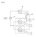
Referring to FIG. 1, the refrigerator in accordance with a preferred embodiment of the present invention includes a compressor 10 for compressing refrigerant, a condenser 20 connected to an outlet side of the compressor 10, a condenser fan 21 for dissipating heat from the condenser 20, a refrigerant valve 30 for blocking a refrigerant flow or shifting a refrigerant flow passage, first and second expansion devices 41 and 42 provided to branch pipes connected to an outlet side of the refrigerant valve 30, a refrigerating chamber evaporator 61, and a freezing chamber evaporator 51 connected to the first and second expansion devices 41 and 42, respectively.
It is preferable that the refrigerant valve 30 is a three-way valve for enabling to be in communication with the freezing chamber evaporator 51 and the refrigerating chamber evaporator 61.
The freezing chamber evaporator 51 is provided in the freezing chamber F and the refrigerating chamber evaporator is provided in the refrigerating chamber R. And, provided to the freezing chamber F and the refrigerating chamber R, there are a freezing chamber cooling air fan 52 and a refrigerating chamber cooling air fan 62 for moving cold air, respectively.
However, it is not necessary to sort the evaporators into the freezing chamber or the refrigerating chamber evaporators clearly, and the sorting of the evaporators can be applied if any one of a plurality of storage chambers has a temperature lower than the other storage chambers.
Moreover, this principle can be applicable to a plurality of refrigerating chambers.
Therefore, if there are a first storage chamber and a second storage chamber having a temperature lower than the first storage chamber, the evaporators can be sorted as a first evaporator for supplying cold air to the first storage chamber and a second evaporator for supplying the cold air to the second storage chamber.
Therefore, the refrigerating chamber evaporator (or the first evaporator) 61 can be replaced with the first evaporator, and the freezing chamber evaporator (or the second evaporator) 51 can be replaced with the second evaporator.
Moreover, the refrigerating chamber R can be a first storage chamber, the freezing chamber F can be a second storage chamber, the refrigerating chamber cooling air fan 62 can be a first cooling air fan, and the freezing chamber cooling air fan 52 can be a second cooling air fan.
It is apparent that the present invention having such elements replaced thus can also be within a scope of the present invention.
Referring to FIG. 2, there is a display unit 70 connected to an output terminal of a control unit 1, for displaying operation states of the compressor 10, the condenser fan 21, the refrigerant valve 30, the refrigerating chamber cooling air fan (or the first cooling air fan) 62, the freezing chamber cooling air fan (or the second cooling air fan) 52, and the refrigerator.
And, there are a power source unit 2 and an input unit 3 having a predetermined input buttons both provided to an input terminal of the control unit 1.
In this instance, the control unit 1 serves to control above elements for forming the cold air in the freezing chamber (or the second storage chamber) (See FIG. 1) and the refrigerating chamber (or the first storage chamber).
And, as described later, at the time an inside pressure of the freezing chamber evaporator (or the second evaporator) 51 is elevated higher than an inside pressure of the refrigerating chamber evaporator (the first evaporator) 61 (See FIG. 1) temporarily, for making the compressor 10 to draw in the remained refrigerant from the freezing chamber evaporator (or the second evaporator) 51, the control unit 1 controls an operation staring time and opening direction and time of the refrigerant valve 30.
FIG. 3 illustrates a schematic view of a state in which one cycle of operation of the compressor 10 is finished and the compressor 10 is turned off.
In this instance, the refrigerant valve 30 is closed not to introduce the refrigerant to the evaporators 51 and 61.
Accordingly, the refrigerant at a relatively high pressure is positioned at a region marked with an A from the compressor 10 to the refrigerant valve 30 through the condenser 20 mostly, and a portion of the refrigerant at a low pressure is positioned at regions except the A region.
FIG. 7 illustrates a graph showing changes of pressures at an inlet and an outlet of the compressor according to turn on/off states of the compressor and open states of the refrigerant valve in the refrigerator in accordance with a preferred embodiment of the present invention.
Referring to FIG. 7, in a state the compressor 10 is turned off and the refrigerant valve 30 is closed both to the freezing chamber evaporator (or the second evaporator) 51 and the refrigerating chamber evaporator (the first evaporator) 61 (Both close) as shown in FIG. 3, an outlet side pressure Pd of the compressor 10 is higher than an inlet side pressure Ps of the compressor 10, significantly (Step I).
The inlet side pressure Ps of the compressor 10 is similar to an inside pressure of the freezing chamber evaporator (or the second evaporator) 51 or the refrigerating chamber evaporator (the first evaporator) 61 both having the refrigerant to be introduced to the inlet side of the compressor 10 contained therein.
This is because the freezing chamber evaporator (or the second evaporator) 51 or the refrigerating chamber evaporator (the first evaporator) 61 is in communication with the inlet side of the compressor 10.
And, this is also because the refrigerant evaporated in the freezing chamber evaporator (or the second evaporator) 51 or the refrigerating chamber evaporator (the first evaporator) 61 is introduced to the inlet side of the compressor 10 without significant change of temperature or pressure in this state.
Therefore, an inside pressure change of the evaporators 51 and 61 will be described with reference to the inlet side pressure Ps of the compressor 10.
In the meantime, referring to FIG. 4, in a state shown in FIG. 3 (the compressor is in a turned off state), the refrigerant valve 30 is operated to introduce the refrigerant to the freezing chamber evaporator (or the second evaporator) 51.
In this instance, it is also made to introduce the refrigerant to the refrigerating chamber evaporator (the first evaporator) 61. However, since what is important is the introduction of the refrigerant to the freezing chamber evaporator (or the second evaporator) 51, the introduction of the refrigerant to the freezing chamber evaporator (or the second evaporator) 51 is required to be a core matter.
This is for elevating the inside pressure of the freezing chamber evaporator (or the second evaporator) 51 higher than the inside pressure of the refrigerating chamber evaporator (the first evaporator) 61. For this, a high pressure refrigerant is forwarded to the freezing chamber evaporator (or the second evaporator) 51 to mix with the refrigerant remained therein.
In this instance, since the refrigerant valve 30 is opened to at least one of the evaporators for introduction of the refrigerant while keeping the compressor 10 to be turned off, an entire refrigerating cycle is made to be in communication, causing the outlet side pressure and the inlet side pressure of the compressor 10 to become the same, substantially (Step II in FIG. 7).
In this instance, in order to introduce the refrigerant both to the freezing chamber evaporator (or the second evaporator) 51 and the refrigerating chamber evaporator (the first evaporator) 61, the refrigerant valve 30 is opened in both evaporator 51 and 61 directions (Refrigerant valve Both open in the step II, See FIG. 7).
However, it is preferable that opening of the refrigerant valve 30 in middle of a closed state is made a predetermined time period before starting of operation of the compressor 10.
If high temperature and high pressure refrigerant relative to the refrigerant remained in the freezing chamber evaporator (or the second evaporator) 51 and the refrigerating chamber evaporator (the first evaporator) 61 is introduced to the evaporators excessively, temperatures and inside pressures of the evaporators 51 and 61 can be elevated, significantly.
Therefore, it is preferable that a time period the refrigerant valve 30 is kept opened from opening of the refrigerant valve 30 to starting of the compressor 10 is matched to a time period required for the inside pressure of the freezing chamber evaporator (or the second evaporator) 51 to be elevated higher than the inside pressure of the refrigerating chamber evaporator (the first evaporator) 61 at the time the compressor in operation.
In detail, it is preferable that the required time period is 1 minute˜1 minute and thirty seconds.
For an example, if the present time is thirty minutes past one o'clock, and the starting time of the compressor 10 is thirty-two minutes past one o'clock, since there are two minutes until starting of the compressor 10, the refrigerant valve 30 is not opened.
However, if the present time is thirty minutes and thirty seconds past one o'clock, or thirty-one minutes past one o'clock, since the time is one minute or one minute and thirty seconds before the starting time of the compressor 10, the refrigerant valve 30 is opened to introduce the refrigerant to the freezing chamber evaporator (or the second evaporator) 51.
This is for introducing the refrigerant from the freezing chamber evaporator (or the second evaporator) 51 of which pressure is higher than the refrigerating chamber evaporator (or the first evaporator) 61 to the compressor entirely in a case the compressor 10 is in operation and evaporation takes place only at the refrigerating chamber evaporator (or the first evaporator) 61 for forming cold air.
According to this, the refrigerant is introduced from the freezing chamber evaporator (or the second evaporator) 51 which does not make any cold air forming action presently to the compressor 10 again and utilized in the refrigeration cycle.
Referring to FIG. 4, if formation of the cold air is required at the refrigerating chamber (or the first storage chamber) R, if the compressor 10 is put into operation, the refrigerant valve 30 is opened for introducing the refrigerant in a refrigerating chamber evaporator (or the first evaporator) direction (Step III in FIG. 7, the refrigerant valve is in a R open state).
Then, the refrigerating chamber cooling air fan (or the first cooling air fan) 62 is come into operation for supplying the cold air to the refrigerating chamber (or the first storage chamber) R.
In this instance, since the refrigerant valve 30 is closed in a freezing chamber evaporator (or the second evaporator) direction, no refrigerant is introduced in the freezing chamber evaporator (or the second evaporator) direction (Step III in FIG. 7, the refrigerant valve is in an F close state).
Formation of the cold air takes place at the refrigerating chamber evaporator (or the first evaporator) 61 owing to evaporation of the refrigerant and heat exchange of the air, but not at the freezing chamber evaporator (or the second evaporator) 51.
Therefore, since the temperature of the refrigerating chamber evaporator (or the first evaporator) 61 is lower than the temperature of the freezing chamber evaporator (or the second evaporator) 51, the inside pressure of the refrigerating chamber evaporator (or the first evaporator) 61 is lower than the inside pressure of the freezing chamber evaporator (or the second evaporator) 51.
This is because the inside pressure of the refrigerating chamber evaporator (or the first evaporator) 61 is dropped by the evaporation even though the inside of the freezing chamber evaporator (or the second evaporator) 51 is influenced by the high pressure refrigerant introduced thereto during the compressor is turned off.
Under this reason, the refrigerant is introduced to the compressor 10 from the freezing chamber evaporator (or the second evaporator) 51 prior to the refrigerating chamber evaporator (or the first evaporator) 61.
If the refrigerant moves from the freezing chamber evaporator (or the second evaporator) 51 to the compressor 10, causing the pressure of the freezing chamber evaporator (or the second evaporator) 51 to drop lower than the pressure of the refrigerating chamber evaporator (or the first evaporator) 61, starting from this time, the refrigerant is drawn into the compressor from an inside of the refrigerating chamber evaporator (or the first evaporator) 61.
Referring to the step III in a graph illustrating the Ps changes in FIG. 7, there are a dashed line marked with F and a solid line marked with R, wherein the F is higher than R.
This indicates that the inside pressure (marked with R) of the refrigerating chamber evaporator (or the first evaporator) under formation of the cold air is lower than the inside pressure of the freezing chamber evaporator (or the second evaporator) (marked with F) not under formation of the cold air.
By forming a pressure difference thus artificially, different from the related art in which additional operation of the compressor is required only for drawing in the refrigerant, by drawing in the refrigerant remained in the freezing chamber evaporator (or the second evaporator) 51 to the compressor 10 without any additional operation of the compressor, shortage of the refrigerant can be prevented.
Since a time period for forming the cold air at the refrigerating chamber evaporator (or the first evaporator) 61 is a ten and a few minutes to a few ten minutes, the drawing in of the refrigerant remained in the freezing chamber evaporator (or the second evaporator) 51 to the compressor 10 can be made within the time period, adequately.
In the meantime, referring to FIG. 6, a requirement for cutting off the refrigerant introduction to the refrigerating chamber evaporator (or the first evaporator) 61 takes place due to formation of an environment, such as the inside temperature of the refrigerating chamber (or the first storage chamber) R reaches to a lower limit, or the like.
And, if introduction of the refrigerant to the freezing chamber evaporator (or the second evaporator) 51 is required for supplying the cold air to the freezing chamber (or the second storage chamber) F, the refrigerant valve 30 blocks a flow passage to the refrigerating chamber evaporator (or the first evaporator) 61 (Step IV in FIG. 7, the refrigerant valve is in a R close state), and opens a flow passage to the freezing chamber evaporator (or the second evaporator) 51 (The refrigerant valve is in an F open state).
And, if a condition something like the inside temperature of the freezing chamber F reaches to a lower limit is met, the compressor 10 is turned off, requiring no more formation of the cold air at the freezing chamber evaporator (or the second evaporator) 51.
Accordingly, the compressor 10 stops operation, and the refrigerant valve 30 blocks the introduction of the refrigerant to the refrigerating chamber evaporator (or the first evaporator) 61 and the freezing chamber evaporator (or the second evaporator) 51 (Step I in FIG. 7, the refrigerant valve 30 is in a Both close state).
Referring to FIG. 7, in the step I, the compressor is in a turned off state, and the refrigerant valve 30 is also in closed states to all of the evaporators. According to this, a difference of inside pressures takes place between the inlet side and the outlet side of the refrigerant valve 30.
In detailed numerical values, the outlet side pressure of the compressor in the step I is about 3.7˜4.0 bar. And, the inlet side pressure of the compressor (substantially the same with the pressure of the evaporators) is about 0.9˜0.95 bar.
Then, if the refrigerant valve 30 is opened in all evaporator directions while the compressor maintains a turned off state in the step II, making all pressures in the cycle the same, the outlet side pressure of the compressor and the inlet side pressure of the compressor (evaporator pressure) becomes in a range of about 1.5˜2.0 bar.
And, in the step III, the compressor is turned on, and the refrigerant valve is opened in a refrigerating chamber evaporator (or the first evaporator) direction (R open), and blocked in a freezing chamber evaporator (or the second evaporator) direction (F close).
Owing to this, even though the inside pressure of the freezing chamber evaporator (or the second evaporator) is maintained the same with 1.5˜2.0 bar in the step II, the inside pressure of the refrigerating chamber evaporator (or the first evaporator) becomes in a range of about 0.95˜1.0 bar as the inside pressure of the refrigerating chamber evaporator (or the first evaporator) is dropped by evaporation for forming the cold air.
Such a pressure difference causes the refrigerant drawn into the compressor from the inside of the freezing chamber evaporator (or the second evaporator) prior to the refrigerant in the refrigerating chamber evaporator (or the first evaporator). In this instance, check valves on pipes connected to the outlets of the evaporators block introduction of the refrigerant from the evaporator which is at higher pressure to the evaporator which is at lower pressure.
In the meantime, after formation of the cold air is finished at the refrigerating chamber, in order to start formation of the cold air at the freezing chamber, an open direction of the refrigerant valve is changed in middle of operation of the compressor like the step IV.
According to this, the refrigerant valve is blocked in the refrigerating chamber evaporator (or the first evaporator) direction (R close) and opened in the freezing chamber evaporator (or the second evaporator) direction (F close). And, the freezing chamber cooling air fan comes into operation, to introduce the cold air into the freezing chamber. And, upon finishing the step IV, the step I state comes again.
Above operation will be summarized by using a flow chart.
Referring to FIG. 8, in a state the compressor is turned off and the refrigerant valve is closed, i.e., in a state introduction of the refrigerant to the refrigerating chamber evaporator (or the first evaporator) and the freezing chamber evaporator (or the second evaporator) are blocked (S801), the present time is compared to a compressor operation starting time, to determine whether the present time is within a predetermined time range or not (S802).
This is for determining a time for introducing the high pressure and high temperature refrigerant remained in an inlet side of the refrigerant valve to the freezing chamber evaporator (or the second evaporator) {and the refrigerating chamber evaporator (or the first evaporator)} during the compressor is turned off.
As a result of the determination, if it is determined that the present time is before a predetermined time range of starting operation of the compressor, the refrigerant valve is opened (S803). Accordingly, the refrigerant is introduced to the freezing chamber evaporator (or the second evaporator) {and the refrigerating chamber evaporator (or the first evaporator)} (S804).
Accordingly, the inside pressure of the freezing chamber evaporator (or the second evaporator) {and the refrigerating chamber evaporator (or the first evaporator)} is elevated.
In this state, it is determined whether the present time is the compressor operation starting time or not (S805), if it is determined that the present time is the compressor operation starting time, the refrigerant valve is operated to block introduction of the refrigerant to the freezing chamber evaporator (or the second evaporator) {That is, the flow passage to the freezing chamber evaporator (or the second evaporator) is blocked} (S806).
Then, a refrigerant introducing state to the refrigerating chamber evaporator (or the first evaporator) is maintained or started {That is, the flow passage to the refrigerating chamber evaporator (or the first evaporator) is opened (S807)}. And, the refrigerating chamber cooling air fan is come into operation for introducing the cold air formed by the refrigerating chamber evaporator (or the first evaporator) to the inside of the refrigerating chamber.
In this state, alike the step III in FIG. 7, since the inside pressure F of the freezing chamber evaporator (or the second evaporator) is higher than the inside pressure R of the refrigerating chamber evaporator (or the first evaporator), the refrigerant can be drawn from the inside of the freezing chamber evaporator (or the second evaporator) to the compressor, causing most of, or entire refrigerant is drawn from the inside of the freezing chamber evaporator (or the second evaporator) to the compressor.
Under this state, it is determined whether formation of the cold air at the refrigerating chamber is required no more or not, and formation of the cold air at the freezing chamber is required or not (S808).
As a result of the determination, if determined required, the refrigerant valve is put into operated again, to block the introduction of the refrigerant to the refrigerating chamber evaporator (or the first evaporator) {That is, the flow passage to the refrigerating chamber evaporator (or the first evaporator) is closed} (S901).
And, the refrigerant valve is opened to the freezing chamber evaporator (or the second evaporator) for introduction of the refrigerant to the freezing chamber evaporator (or the second evaporator). {That is, the flow passage to the freezing chamber evaporator (or the second evaporator) is opened} (S902).
And, the freezing chamber cooling air fan (or the second cooling air fan) is put into operation, for introducing the cold air formed by the freezing chamber evaporator (or the second evaporator) to the inside of the freezing chamber (or the second storage chamber).
After a certain time period is passed after the formation of the cold air takes place for cooling the freezing chamber (or the second storage chamber), whether a compressor turn off condition is met or not is determined owing to completion of a compressor operation time period or meeting a temperature condition of the freezing chamber (or the second storage chamber) or the refrigerating chamber (or the first storage chamber) (S903).
Accordingly, if it is determined that the compressor operation time period is completed, or the inside temperature of the freezing chamber (or the second storage chamber) or the refrigerating chamber (or the first storage chamber) meets a predetermined temperature condition, the compressor is turned off (S904).
Then, the refrigerant valve is closed, preventing the refrigerant from introducing to the freezing chamber evaporator (or the second evaporator) and the refrigerating chamber evaporator (or the first evaporator) (S905).
It will be apparent to those skilled in the art that various modifications and variations can be made in the present invention without departing from the spirit or scope of the inventions. Thus, it is intended that the present invention covers the modifications and variations of this invention provided they come within the scope of the appended claims and their equivalents.

Claims (11)

The invention claimed is:
1. A method for controlling a refrigerator having a compressor, a refrigerant valve connected to the compressor for guiding refrigerant from the compressor, and a refrigerating chamber evaporator and a freezing chamber evaporator provided to branch pipes connected to an outlet side of the refrigerant valve, comprising:
(A) a step of turning off the compressor and closing the refrigerant valve for blocking the refrigerant to the freezing chamber evaporator and the refrigerating chamber evaporator;
(B) a step of controlling the refrigerant valve for introducing the refrigerant to the freezing chamber evaporator during a turn off state of the compressor; and
(C) a step of putting the compressor into operation, and controlling the refrigerant valve for introducing the refrigerant into the refrigerating chamber evaporator and for blocking the refrigerant to the freezing chamber evaporator for maintaining an inside pressure of the freezing chamber evaporator higher than an inside pressure of the refrigerating chamber evaporator, such that the refrigerant from the freezing chamber evaporator is collected,
wherein the step (B) includes the steps of:
(B-1) determining whether or not a present time is within a predetermined time range from a compressor operation starting time, and
(B-2) when the present time is within the predetermined time range, opening the refrigerant valve to introduce the refrigerant, the refrigerant remained at an inlet side of the refrigerant valve due to turning off of the compressor and closure of the refrigerant valve, only to the freezing chamber evaporator.
2. The method as claimed in claim 1, wherein the predetermined time range in which the refrigerant valve is kept opened in the step (B-2) is a time period required for elevating the inside pressure of the freezing chamber evaporator to be higher than the inside pressure of the refrigerating chamber evaporator in the step (C).
3. The method as claimed in claim 2, wherein the predetermined time range is one minute to one minute thirty seconds.
4. The method as claimed in claim 1, further comprising:
(D) a step of controlling the refrigerant valve to block the introduction of the refrigerant to the refrigerating chamber evaporator and to open introduction of the refrigerant to the freezing chamber evaporator if stopping introduction of the refrigerant to the refrigerating chamber evaporator is required during operation of the compressor.
5. The method as claimed in claim 1, wherein a time period in which the refrigerant is kept introduced to the refrigerating chamber evaporator in the step (C) is provided longer than a time period in which the refrigerant remained in the freezing chamber evaporator is drawn into the compressor, entirely.
6. A method for controlling a refrigerator having a first storage chamber, a second storage chamber having a temperature kept lower than the first storage chamber, a compressor, a refrigerant valve connected to the compressor, and first and second evaporators provided to branch pipes connected to an outlet side of the refrigerant valve for forming cold air to be supplied to the first and second storage chambers respectively, wherein the refrigerant valve is for guiding the refrigerant to the first and second evaporators, the method comprising:
(1) a step of turning off the compressor and closing the refrigerant valve for blocking the refrigerant to the second evaporator and the first evaporator;
(2) a step of controlling the refrigerant valve to supply the refrigerant to the second evaporator to elevate an inside pressure of the second evaporator in a state the compressor is turned off;
(3) a step of controlling the refrigerant valve to supply the refrigerant to the first evaporator if supply of the refrigerant to the first storage chamber is required with putting the compressor into operation; and
(4) a step of controlling the refrigerant valve to block introduction of the refrigerant to the second evaporator for elevating the inside pressure of the second evaporator higher than the inside pressure of the first evaporator in order to recover the refrigerant from the second evaporator during the step (3),
wherein the step (2) includes the step of controlling the refrigerant valve to supply the refrigerant, remained at an inlet side of the refrigerant valve due to turning off of the compressor and closure of the refrigerant valve, only to the second evaporator for a predetermined time period before starting of the compressor.
7. The method as claimed in claim 6, wherein the time period in which the refrigerant valve is kept opened in the step (4) is a time period in which the inside pressure of the second evaporator is elevated higher than the inside pressure of the first evaporator formed in the step (3).
8. The method as claimed in claim 6, further comprising:
(5) a step of controlling the refrigerant valve to guide introduction of the refrigerant to the second evaporator and to block the introduction of the refrigerant to the first evaporator, if stopping introduction of the refrigerant to the first evaporator is required during operation of the compressor.
9. The method as claimed in claim 6, wherein a time period in which the refrigerant is kept introduced to the first evaporator in the step (3) is provided longer than a time period in which the refrigerant remained in the second evaporator is drawn into the compressor entirely.
10. A refrigerator comprising:
a compressor;
a refrigerating chamber evaporator and a freezing chamber evaporator;
refrigerant valve for guiding refrigerant to the refrigerating chamber evaporator or the freezing chamber evaporator; and
a control unit controlling the refrigerant valve and the compressor,
wherein the control unit controls:
the compressor being turned off and the refrigerant valve to block the refrigerant to the freezing chamber evaporator and the refrigerating chamber evaporator;
the refrigerant valve to introduce the refrigerant to the freezing chamber evaporator in a state the compressor is turned off; and
the compressor to be turned on and the refrigerant valve to block the refrigerant to the freezing chamber evaporator and to introduce the refrigerant to the refrigerating chamber evaporator to cause an inside pressure of the freezing chamber evaporator to be elevated higher than an inside pressure of the refrigerating chamber evaporator during evaporation at the refrigerating chamber evaporator for the compressor to draw in the refrigerant remained in the freezing chamber evaporator, and
wherein the control unit controls the refrigerant valve such that the refrigerant is introduced only to the freezing chamber evaporator at the time the compressor is turned off.
11. The refrigerator as claimed in claim 10, wherein at the time the compressor is started to operate, the refrigerant valve is opened to the refrigerating chamber evaporator and closed to the freezing chamber evaporator, and
wherein the refrigerant valve is kept closed to the freezing chamber evaporator until the inside pressure of the freezing chamber evaporator is kept higher than the inside pressure of the refrigerating chamber evaporator for drawing refrigerant remained in the freezing chamber evaporator is drawn to the compressor, entirely.
US13/520,058 2010-01-22 2011-01-19 Refrigerator and method for controlling the same Active 2034-03-26 US9816749B2 (en)

Applications Claiming Priority (3)

Application Number Priority Date Filing Date Title
KR1020100006024A KR101658552B1 (en) 2010-01-22 2010-01-22 A refrigerator and a control method thereof
KR10-2010-0006024 2010-01-22
PCT/KR2011/000380 WO2011090309A2 (en) 2010-01-22 2011-01-19 Refrigerator and method for controlling the same

Publications (2)

Publication Number Publication Date
US20120272674A1 US20120272674A1 (en) 2012-11-01
US9816749B2 true US9816749B2 (en) 2017-11-14

Family

ID=44307385

Family Applications (1)

Application Number Title Priority Date Filing Date
US13/520,058 Active 2034-03-26 US9816749B2 (en) 2010-01-22 2011-01-19 Refrigerator and method for controlling the same

Country Status (3)

Country Link
US (1) US9816749B2 (en)
KR (1) KR101658552B1 (en)
WO (1) WO2011090309A2 (en)

Families Citing this family (7)

* Cited by examiner, † Cited by third party
Publication number Priority date Publication date Assignee Title
US9618246B2 (en) * 2012-02-21 2017-04-11 Whirlpool Corporation Refrigeration arrangement and methods for reducing charge migration
US9733008B2 (en) * 2013-03-13 2017-08-15 Whirlpool Corporation Air flow design for controlling temperature in a refrigerator compartment
KR20140115838A (en) * 2013-03-22 2014-10-01 엘지전자 주식회사 Method for controlling refrigerator
US10697679B2 (en) * 2015-06-08 2020-06-30 Electrolux Appliances Aktiebolag Cooling system and a method for control thereof
KR20170067559A (en) * 2015-12-08 2017-06-16 엘지전자 주식회사 A refrigerator and a method for controlling the same
JP6803217B2 (en) * 2016-12-15 2020-12-23 三星電子株式会社Samsung Electronics Co.,Ltd. refrigerator
CN114562848A (en) * 2022-02-08 2022-05-31 珠海格力电器股份有限公司 Refrigerator refrigeration system with humidity adjustment function, refrigerator and control method

Citations (18)

* Cited by examiner, † Cited by third party
Publication number Priority date Publication date Assignee Title
US3448916A (en) * 1967-06-16 1969-06-10 Ingersoll Rand Co Unloading system for compressors
US4441335A (en) * 1982-08-19 1984-04-10 Honeywell Inc. Heat pump
US6253561B1 (en) * 1998-09-18 2001-07-03 Kabushiki Kaisha Toshiba Refrigerator with switching valve switching flow of refrigerant to one of refrigerant passages
US6370895B1 (en) * 1999-09-21 2002-04-16 Kabushiki Kaisha Toshiba Refrigerator with two evaporators
US20020043073A1 (en) * 2000-10-12 2002-04-18 Lg Electronics Inc. Apparatus and method for controlling refrigerating cycle of refrigerator
US6397608B1 (en) * 1999-11-30 2002-06-04 Kabushiki Kaisha Toshiba Refrigerator
US20020134095A1 (en) * 2001-03-21 2002-09-26 Minoru Temmyo Refrigerator with a plurality of parallel refrigerant passages
US20050086952A1 (en) * 2001-09-19 2005-04-28 Hikaru Nonaka Refrigerator-freezer controller of refrigenator-freezer, and method for determination of leakage of refrigerant
US20050103029A1 (en) * 2002-01-15 2005-05-19 Keizou Kawahara Refrigerator having alarm device for alarming leakage of refrigerant
US20060144063A1 (en) * 2004-12-30 2006-07-06 Samsung Electronics Co., Ltd. Method for controlling operation of refrigerator
US20070113567A1 (en) * 2005-11-23 2007-05-24 Samsung Electronics Co., Ltd. Refrigerator and control method thereof
DE102006015989A1 (en) 2006-04-05 2007-10-11 BSH Bosch und Siemens Hausgeräte GmbH Method for operating a refrigeration device with parallel-connected evaporators and refrigeration device therefor
EP2019275A1 (en) 2006-05-15 2009-01-28 Hoshizaki Denki Kabushiki Kaisha Cooling storage compartment and its operating method
WO2009051030A1 (en) 2007-10-19 2009-04-23 Ishida Co., Ltd. Strip pack device
US20090113904A1 (en) * 2007-11-05 2009-05-07 Young Hoon Yun Method for controlling a refrigerator
US20090282849A1 (en) * 2005-11-30 2009-11-19 Shuuji Fujimoto Refrigeration System
US20130340457A1 (en) * 2012-06-25 2013-12-26 Whirlpool Corporation Fault detection and diagnosis for refrigerator from compressor sensor
US20150000318A1 (en) * 2011-12-20 2015-01-01 Dometic S.A.R.L. Cooling device and method for controlling a cooling device

Patent Citations (20)

* Cited by examiner, † Cited by third party
Publication number Priority date Publication date Assignee Title
US3448916A (en) * 1967-06-16 1969-06-10 Ingersoll Rand Co Unloading system for compressors
US4441335A (en) * 1982-08-19 1984-04-10 Honeywell Inc. Heat pump
US6253561B1 (en) * 1998-09-18 2001-07-03 Kabushiki Kaisha Toshiba Refrigerator with switching valve switching flow of refrigerant to one of refrigerant passages
US6370895B1 (en) * 1999-09-21 2002-04-16 Kabushiki Kaisha Toshiba Refrigerator with two evaporators
US6397608B1 (en) * 1999-11-30 2002-06-04 Kabushiki Kaisha Toshiba Refrigerator
US20020043073A1 (en) * 2000-10-12 2002-04-18 Lg Electronics Inc. Apparatus and method for controlling refrigerating cycle of refrigerator
US20020134095A1 (en) * 2001-03-21 2002-09-26 Minoru Temmyo Refrigerator with a plurality of parallel refrigerant passages
US20050086952A1 (en) * 2001-09-19 2005-04-28 Hikaru Nonaka Refrigerator-freezer controller of refrigenator-freezer, and method for determination of leakage of refrigerant
US20050103029A1 (en) * 2002-01-15 2005-05-19 Keizou Kawahara Refrigerator having alarm device for alarming leakage of refrigerant
US20060144063A1 (en) * 2004-12-30 2006-07-06 Samsung Electronics Co., Ltd. Method for controlling operation of refrigerator
US20070113567A1 (en) * 2005-11-23 2007-05-24 Samsung Electronics Co., Ltd. Refrigerator and control method thereof
US20090282849A1 (en) * 2005-11-30 2009-11-19 Shuuji Fujimoto Refrigeration System
DE102006015989A1 (en) 2006-04-05 2007-10-11 BSH Bosch und Siemens Hausgeräte GmbH Method for operating a refrigeration device with parallel-connected evaporators and refrigeration device therefor
US20090173086A1 (en) * 2006-04-05 2009-07-09 Bsh Bosch Und Siemens Hausgerate Gmbh Method for operating a refrigerating device comprising evaporators which are connected in parallel and refrigerating device therefor
EP2019275A1 (en) 2006-05-15 2009-01-28 Hoshizaki Denki Kabushiki Kaisha Cooling storage compartment and its operating method
WO2009051030A1 (en) 2007-10-19 2009-04-23 Ishida Co., Ltd. Strip pack device
US20090113904A1 (en) * 2007-11-05 2009-05-07 Young Hoon Yun Method for controlling a refrigerator
KR20090046152A (en) 2007-11-05 2009-05-11 엘지전자 주식회사 Refrigerator Control Method
US20150000318A1 (en) * 2011-12-20 2015-01-01 Dometic S.A.R.L. Cooling device and method for controlling a cooling device
US20130340457A1 (en) * 2012-06-25 2013-12-26 Whirlpool Corporation Fault detection and diagnosis for refrigerator from compressor sensor

Also Published As

Publication number Publication date
WO2011090309A2 (en) 2011-07-28
US20120272674A1 (en) 2012-11-01
KR20110086343A (en) 2011-07-28
KR101658552B1 (en) 2016-09-21
WO2011090309A3 (en) 2012-08-09

Similar Documents

Publication Publication Date Title
US9816749B2 (en) Refrigerator and method for controlling the same
KR101314622B1 (en) Controlling method for the refrigerator
CN111692708B (en) Air conditioning system with frosting inhibition function and frosting inhibition control method
US11885518B2 (en) Air-conditioning apparatus
US8141372B2 (en) Method for operating a refrigerating device comprising evaporators which are connected in parallel and refrigerating device therefor
CN102102933B (en) The method of refrigerator and its operation of control
KR102122499B1 (en) A cooling system and a control method the same
US20130340469A1 (en) Refrigerator
CN1979064A (en) Refrigerator and method for controlling the same
JP4804528B2 (en) Refrigeration cycle apparatus and control method for refrigeration cycle apparatus
CN101344340B (en) Air conditioner
CN113701375A (en) Frostless type refrigeration house and control method thereof
KR20210075922A (en) A refrigerator
CN112611154A (en) Parallel double-system refrigerator and defrosting control method
KR101695689B1 (en) Refrigerator
CN105556221A (en) Refrigerating device
EP1376031A2 (en) Method for controlling operation of cooling system having two evaporators
US20140284024A1 (en) Method for controlling refrigerator
CN106091457B (en) Refrigeration system and its control method and control device, refrigerator
US11965683B2 (en) Cooling system for low temperature storage
JPH09210515A (en) Refrigeration equipment
CN206146042U (en) Heat pump system and refrigerating unit
CN113915784A (en) Refrigerator and refrigeration control method thereof
KR101908307B1 (en) Refrigeration system
KR20050063218A (en) Refrigerating cycle in direct cooling type refrigerator and method thereof

Legal Events

Date Code Title Description
AS Assignment

Owner name: LG ELECTRONICS INC., KOREA, REPUBLIC OF

Free format text: ASSIGNMENT OF ASSIGNORS INTEREST;ASSIGNOR:LIM, HYOUNG KEUN;REEL/FRAME:028478/0121

Effective date: 20120521

STCF Information on status: patent grant

Free format text: PATENTED CASE

MAFP Maintenance fee payment

Free format text: PAYMENT OF MAINTENANCE FEE, 4TH YEAR, LARGE ENTITY (ORIGINAL EVENT CODE: M1551); ENTITY STATUS OF PATENT OWNER: LARGE ENTITY

Year of fee payment: 4

MAFP Maintenance fee payment

Free format text: PAYMENT OF MAINTENANCE FEE, 8TH YEAR, LARGE ENTITY (ORIGINAL EVENT CODE: M1552); ENTITY STATUS OF PATENT OWNER: LARGE ENTITY

Year of fee payment: 8