US981663A - Straight hosiery-frame. - Google Patents
Straight hosiery-frame. Download PDFInfo
- Publication number
- US981663A US981663A US56338810A US1910563388A US981663A US 981663 A US981663 A US 981663A US 56338810 A US56338810 A US 56338810A US 1910563388 A US1910563388 A US 1910563388A US 981663 A US981663 A US 981663A
- Authority
- US
- United States
- Prior art keywords
- frame
- bar
- cam
- yarn guide
- slide
- Prior art date
- Legal status (The legal status is an assumption and is not a legal conclusion. Google has not performed a legal analysis and makes no representation as to the accuracy of the status listed.)
- Expired - Lifetime
Links
Images
Classifications
-
- D—TEXTILES; PAPER
- D04—BRAIDING; LACE-MAKING; KNITTING; TRIMMINGS; NON-WOVEN FABRICS
- D04B—KNITTING
- D04B15/00—Details of, or auxiliary devices incorporated in, weft knitting machines, restricted to machines of this kind
- D04B15/38—Devices for supplying, feeding, or guiding threads to needles
- D04B15/54—Thread guides
- D04B15/64—Thread guides for straight-bar knitting machines
Definitions
- I provide the straight hosiery framewith two main slides guided in the frame proper and operated by a screw-spindle with rightand lefthanded threads. Each main slide is provided with a subsidiary slide guided in it parallel to the yarn guide bars.
- each stop On each subsidiary slide as many adjustable stops are provided, as there are yarn guide bars, each stop being adapted to come in contact with one lug on any of the yarn guide bars and to move with same while retarding it, until both stop.
- a controlling slide In each main guide moreover a controlling slide is guided in a direction at right angles to the yarn guide bars and the controlling slide is provided with a crooked slot, in Whlch a pin on the subsidiary slide engages.
- I further provide the machine with a cam bar parallel to the yarn guide bars, which cam bar is guided in the frame proper and has two cams, over which rollers at the lower ends of the two controlling slides can roll, so that b the cams the controlling slides can be alternately raised and lowered, while at the same time by the controlling slides the subsidiary slidecrease longitudinally moved in one and the other direction.
- Means are provided for longitudinally rethat of the yarn guide bar and the motion; of the subsidiary slide is then reversed at the moment that its respective stop is about to come in contact with the corresponding lug of the yarn guide bar, so that the shock or blow produced by the lug striking.
- the stop is considerably softened or annihilated, the more so, since by the stop moving with the subsidiary slide in the same direction the motion of the lug and of its bar is gradually retarded, until both stop at the moment that the motion of the yarn guide bar is reversed.
- the said screw-spindle with rightand left-handed threads serves for feeding the two main slides in opposite direct-ions during the widening or narrowing of the goods, in other words for varying the stroke of the yarn guide bar.
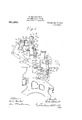
- Figure 1 is a vertical central cross section through a Cotton type straight hosiery frame provided with the improvements according to my invention, only so much of the machine being shown as is necessary for giving a sufficient idea.
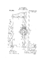
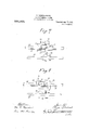
- Fig. 2 is a vertical longitudinal sect-ion through the broken line AB in Fig. 1 and shows the middle part of the machine.
- Fig. 3 is a plan viewo'f the parts shown at Fig. 2.
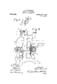
- Fig. 4 is a front elevation of the parts in the middle portion of the frame.
- Fig. 5 is a vertical cross section through the line C-D in Fig. 4, seen in the direction of the arrows.
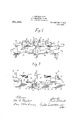
- Fig. 7 is a detail view of some of the parts shown in Fig. 2, with the cam bar in another position
- Fig. 8 is a similar view and shows the cam bar in athird position.
- a cam shaft 1 is mounted in the frame 2 to turn and is arranged to be driven from some countershaft by means of gearing (not shown) and carries various cam disks, of which only a few are shown at Fig. 1.
- the cam disks 3 are adapted to operate the machine needle bar 4 by means of rollers 5, arms 6, a rocking shaft 7 and arms 8.
- Fig. 6 is a The. frame needle bar 4 is fastened on'the upper short arms 9 of two-armed levers 9, 10, which are mounted to rock on plns 11 at the free ends of the arms 8, while their lower long arms are pivotally connected by rods 12 with pins 13 on arms 14 fastened on a rocking shaft 15.
- the arms 14 carry rollers 16 and are therewith pressed by helical springs 17 against the periphery of cam disks 18 on the cam shaft 1, while the above mentioned rollers 5 are pressed by helical springs 19 against their cam disks 3.
- the frame needle bar 4 can be raised and lowered by the parts3, 5, 6, 7, 8 and rocked about the pins 11 as usual.
- the frame needles ar denote by 2 I do not further describe them','nor the slnkers working them, as they are immaterial to my invention.
- Two parallel horizontal rods 21 and 22 are provided in the frame 2 andtwo opposite main slides 23 and 24 are mounted on the upper rod 22 to' longitudinally move.
- the two main slides 23 and 24 form nuts of a horizontal left and right-handed screwspindle 25, which is mounted to. turn in three bearings 26,26 loose on the rod 22.
- the bearings 26, 26 are rigidly connected with three supports 27, v27, which are loose on the lower. rod 21.
- the middle bearing 26 is assumed'to be located in the middle of the hosiery frame, and it will be seen, that by the three bearings 26, 26 and. the three supports 27, 27 the two main slides 23.and-' 24 are prevented from turning on the rod 22.
- the screw-spindle 25 carries at the right end in Fig. 3 a hand-crank 28 and at the left en'd'a ratchet wheel 29- with four teeth. Loose on a shaft 30 forming-part of the hosiery frame is a two-armed lever 31,
- a subsidiaryslide 47 is horizontally guided in one main slide 23 and has an arm 48, on
- cam disk 72 from opposite sides.
- a controlling slide 57 is verticallyguided in one main slide 23 and a second controlling t,
- the con-' trolllng slide 57 has a crooked oblique slot 59,
- the other controlling slide 58 has I an opposite slot 61, in which a pin 62 on the 90 other subsidiary slide 52 engages. The conengages.
- trolling slide 57 carries at its lower end a roller 63, which is adapted to'roll on a cam bar 64 and over a cam 65 provided on the latter.
- the other controlling. slide 58 likewise carries at its lower end a roller 66,
- the two controllingslides 57 and 58 may be pressed downward by their own weight or by. springs 100 of any known kind (not shown).
- the cam bar 64- is horizontally guided in the frame 2 and-carries apin 68 which is operated from the cam shaft 1 in the follow-v ing manner.
- a suitable part of the frame 2 carries a pin 73 on which a link 74 is mounted to rock, and another part of the frame 2 carries a pin 75, onwhich a lever 76 can rock. At the upper end. the lever 76 has a sl ot 77, in which the said pin 68 engages.
- the link 74 is pivotally connected with the lever 76 by a rod 78 carryonly difference being, that they actuate thev cam bar 64 and not the knownslide carrying .75 t and the other lug 41 is adapted to come in contact with the stop 49 for stopping the bar 35.
- the two lugs 43 and 44 the yarn guide-bars.
- the cam bar 64 car ries several bearings 81,81, in which a shaft 82 is mounted to rock, while it is in any known manner prevented from longitudinal motion so that it is obliged to partake in the reciprocating motion of the cam bar 64.
- the right end of the shaft 82 in Fig. 4 passes through the nave of an arm 83 (Fig. 5) and is provided with a groove, in which a feather in this nave engages.
- the arm 83 is in any known manner prevented from endwise motion and is pivotally connected with a vertical rod 84, which is operated from any known device that ordinarily serves for pcriodically changing the connection shown at 85, 88, 89 from one yarn guide bar to any of the other yarn guide bars.
- the three yarn guide bars 35, 36, 37 have fastened on them inclined forks 85, 86, 87 respectively, into any of which an arm 88 fastened on a sleeve 89 can engage.
- the sleeve 89 is in any known manner prevented from turning on the shaft 82 and is frictionally held thereon, so that it normally moves together with the latter, but on being stopped in a manner to be described later on it can slide on the shaft 82.
- the straight hosiery frame operates as follows: By turning the hand-crank 28 the two main slides 23 and 24 are moved away from one another into their initial position. When the machine is in working order and at a moment the arm 88 on the sleeve 89 engages the fork 85 on the front yarn guide bar 35 and the cam bar 64 is moved from right to left in the dirmtionof the arrow 90 in Figs. 7 and 8, about in the middle of the stroke of the cam bar 64 the roller 66 of the right controlling slide 58 will occupy the position shown at Fig.
- the left cam 65 is able to produce a gradual and silent stoppage of the front the cam shaft 1, so that the two main slides- 23 and 24 are simultaneously moved together through the distance of one or several pitches of the frame needles 20, as the case may be, whereby the stroke of any of the yarn guide bars 35, 36, 37 is graduallyshorte-ned as usual.
- the rod 84 (Fig.5) is so actuated, as to move by the arm 83 and the shaft 82;,the arm 88 of the sleeve 89 out of engagement with the fork 85 of the front yarn guide bar 35 into engagement with say the fork 87 ofthe rear yarn guide bar 37, the latter will be alternately and gradually stopped by the two adjustable stops 51 and 56 in a similar manner to that described above with reference to the front yarn guide 35.
- each controlling slide having an inclined slot opposite to that of the other controlling slide which slot is adapted to uide the pin of the corresponding subsi iary slide, stops on said two subsidiary slides, each stop being adapted to come in contact with one lug of the corresponding yarn guide bar and to move with same while retarding it until both stop, a mechanism for feeding said two main slides in opposite directions, means for yieldingly connecting any of said yam guide bars with said cam bar, and means for longitudinally reciprocating said cam bar.
Description
T. LIEBERKNEGHT. STRAIGHT HOSIERY FRAME.
APPLICATION FILED MAY 25,1910.
Patented Jan. 17, 1911.
5 SHEETS-SHEET 1.
T." LIEBERKNEUHT. STRAIGHT HOSIERY FRAME.
APPLIOATION FILED MAY 25,1910.
5 SHEETS-SHEET 2.
Away
1 663 Patented Jan. 17, 1911.
T. LIEBERKNEGHT. STRAIGHT HOSIERY FRAME. APPLICATION FILED MAY 25,1910.
Patented"Jan.;17,l1911.
T. LIEBERKNEGHT.
STRAIGHT HOSIBBY FRAME. APPLICATION FILED MAY 25, 1910.
Patented Jan. 17, 1911.
5 SHEETS-SHEET 4.
T. LIEBERKNBGHT. STRAIGHT HOSIERY FRAME.
APPLICATION FILED MAY 25,1910.
5 SHEETS-SHEET 5.
' Patented Jan. 17, 191 1.
UNITE THEODOR LIEBERKNECHT, OF HOHENSTEIN-ERNSTTHAL, GERMANY.
STRAIGHT HOSIERY-FRAME.
Specification of Letters Patent.
Application filed May 25, 1910. Serial No. 568,388.
Patented Jan. 17, 1911.
To all whom it may concern: 7
Be it known that I, THEODOR ,LIEBER- KNECHT, a citizen of the Empire of Germany, residing at Hohenstein-Ernstthal i. S., in the Empire of Germany, have in vented a new and useful Straight Hosiery- Fr'ame, of which the following is a specification.
, chines can be driven at a greater speed than My invention relates to improvements in straight hosiery frames adapted to simultaneously produce a number of like hosiery pieces, whereby the shocks or blows produced by the yarn guide bars striking the known shiftable stops are considerably softened or'nearly annihilated, so that the mahitherto and consequently their output will be increased. I provide the straight hosiery framewith two main slides guided in the frame proper and operated by a screw-spindle with rightand lefthanded threads. Each main slide is provided with a subsidiary slide guided in it parallel to the yarn guide bars. On each subsidiary slide as many adjustable stops are provided, as there are yarn guide bars, each stop being adapted to come in contact with one lug on any of the yarn guide bars and to move with same while retarding it, until both stop. In each main guide moreover a controlling slide is guided in a direction at right angles to the yarn guide bars and the controlling slide is provided with a crooked slot, in Whlch a pin on the subsidiary slide engages. I further provide the machine with a cam bar parallel to the yarn guide bars, which cam bar is guided in the frame proper and has two cams, over which rollers at the lower ends of the two controlling slides can roll, so that b the cams the controlling slides can be alternately raised and lowered, while at the same time by the controlling slides the subsidiary slidesoare longitudinally moved in one and the other direction.
Means are provided for longitudinally rethat of the yarn guide bar and the motion; of the subsidiary slide is then reversed at the moment that its respective stop is about to come in contact with the corresponding lug of the yarn guide bar, so that the shock or blow produced by the lug striking. the stop is considerably softened or annihilated, the more so, since by the stop moving with the subsidiary slide in the same direction the motion of the lug and of its bar is gradually retarded, until both stop at the moment that the motion of the yarn guide bar is reversed. The said screw-spindle with rightand left-handed threads serves for feeding the two main slides in opposite direct-ions during the widening or narrowing of the goods, in other words for varying the stroke of the yarn guide bar.
I will now roceed to describe my invention with reference to the accompanying drawings, in which Figure 1 is a vertical central cross section through a Cotton type straight hosiery frame provided with the improvements according to my invention, only so much of the machine being shown as is necessary for giving a sufficient idea. Fig. 2 is a vertical longitudinal sect-ion through the broken line AB in Fig. 1 and shows the middle part of the machine. Fig. 3 is a plan viewo'f the parts shown at Fig. 2. Fig. 4 is a front elevation of the parts in the middle portion of the frame. Fig. 5 is a vertical cross section through the line C-D in Fig. 4, seen in the direction of the arrows. vertical cross section through the straight hosiery frame on a line to the left of the parts shown in Fig. 4, only those portions of the mechanism required to illustrate the invention being shown. Fig. 7 is a detail view of some of the parts shown in Fig. 2, with the cam bar in another position, and Fig. 8 is a similar view and shows the cam bar in athird position.
Similar characters of reference refer to similar parts throughout the several views.
In the drawings I have shownfor example a straight hosiery frame of the known Cottons construction, which is adapted to simultaneously produce a number of like goods. A cam shaft 1 is mounted in the frame 2 to turn and is arranged to be driven from some countershaft by means of gearing (not shown) and carries various cam disks, of which only a few are shown at Fig. 1. The cam disks 3 are adapted to operate the machine needle bar 4 by means of rollers 5, arms 6, a rocking shaft 7 and arms 8.
Fig. 6 is a The. frame needle bar 4 is fastened on'the upper short arms 9 of two-armed levers 9, 10, which are mounted to rock on plns 11 at the free ends of the arms 8, while their lower long arms are pivotally connected by rods 12 with pins 13 on arms 14 fastened on a rocking shaft 15. The arms 14 carry rollers 16 and are therewith pressed by helical springs 17 against the periphery of cam disks 18 on the cam shaft 1, while the above mentioned rollers 5 are pressed by helical springs 19 against their cam disks 3. In this manner the frame needle bar 4 can be raised and lowered by the parts3, 5, 6, 7, 8 and rocked about the pins 11 as usual.
The frame needles ar denote by 2 I do not further describe them','nor the slnkers working them, as they are immaterial to my invention.
Two parallel horizontal rods 21 and 22 are provided in the frame 2 andtwo opposite main slides 23 and 24 are mounted on the upper rod 22 to' longitudinally move.
The two main slides 23 and 24 form nuts of a horizontal left and right-handed screwspindle 25, which is mounted to. turn in three bearings 26,26 loose on the rod 22. The bearings 26, 26 are rigidly connected with three supports 27, v27, which are loose on the lower. rod 21. The middle bearing 26 is assumed'to be located in the middle of the hosiery frame, and it will be seen, that by the three bearings 26, 26 and. the three supports 27, 27 the two main slides 23.and-' 24 are prevented from turning on the rod 22. The screw-spindle 25 carries at the right end in Fig. 3 a hand-crank 28 and at the left en'd'a ratchet wheel 29- with four teeth. Loose on a shaft 30 forming-part of the hosiery frame is a two-armed lever 31,
32, of which the upper arm 31- carries a long pawl 34 engaging the ratchet wheel 29 and the lower arm 32 carries a roller 33 adapted to roll on. one of the cam disks 3.
Itgwill be imderstood, that by means of the pawl 34, the ratchet wheel 29 and the screw- 1 spindle 25 the two main slides 23 and 24 can be fed toward one another to control thetraverse of the yarn guides when narrowing the goods and after finishing the gobds or their portions the two main slides can be returned to their initial position by turning the hand-crank 28. Three. yarn gulde bars 35, 36, 37 parallel-to the two rods 21 and 22 and to the series of frame needles 20 are shown to be provided, which are mounted in the frame 2 to longitudinallyreciprocate and carry yarn guides 38, 39, 40 (Fig. 1), of which onl one '38 is shown in Fig. 4. The yarn gulde bars 35, 36, 37 have fastened on them near their middle two lugs each, viz'. 41 and 42 nthe bar 35, 43 and 44 on the bar 36, v 45 and 46 on the bar ,37.
A subsidiaryslide 47 is horizontally guided in one main slide 23 and has an arm 48, on
the cam disk 72 from opposite sides.
which three vertically adjustable stops 49, v 50, 51 are shown to be provided about in the vertical planes of the three yarn guide bars 35, 36, 37. Another subsidiary slide 52 opposite to the first one 47 is guided in the 70 other main slide 24 and has an arm 53, on which three vertically adjustable stops 54, 55, 56 are provided. The lug-42 of'the yarn guide bar 35 is adapted to come in contact with the stop 54, whereby the bar is stopped,
o the second yarn guide bar 36 are in a similar m'anner adapted to work with the stops and. 55, and the two lugs 45 and 46 of the third yarn guide bar 37 are adapted to workwith the two stops .51 and 56 respectively. A controlling slide 57 is verticallyguided in one main slide 23 and a second controlling t,
in which a pin 60 on the subsidiary slide 47 s The other controlling slide 58 has I an opposite slot 61, in which a pin 62 on the 90 other subsidiary slide 52 engages. The conengages.
trolling slide 57 carries at its lower end a roller 63, which is adapted to'roll on a cam bar 64 and over a cam 65 provided on the latter. The other controlling. slide 58 likewise carries at its lower end a roller 66,
which is adapted to roll' on the cam bar 64 and over; a. second camv 67. The two controllingslides 57 and 58 may be pressed downward by their own weight or by. springs 100 of any known kind (not shown).
The cam bar 64-is horizontally guided in the frame 2 and-carries apin 68 which is operated from the cam shaft 1 in the follow-v ing manner. A small bevel wheel 69 splined, 1 5:
on the cam shaft 1 meshes with a large bevel I wheel 70 keyed upon a shaft 71, which turns in the frame 2 and has fastened on it --at the rear end a cam-disk 72. A suitable part of the frame 2 carriesa pin 73 on which a link 74 is mounted to rock, and another part of the frame 2 carries a pin 75, onwhich a lever 76 can rock. At the upper end. the lever 76 has a sl ot 77, in which the said pin 68 engages. The link 74 is pivotally connected with the lever 76 by a rod 78 carryonly difference being, that they actuate thev cam bar 64 and not the knownslide carrying .75 t and the other lug 41 is adapted to come in contact with the stop 49 for stopping the bar 35. The two lugs 43 and 44 the yarn guide-bars. The cam bar 64 car ries several bearings 81,81, in which a shaft 82 is mounted to rock, while it is in any known manner prevented from longitudinal motion so that it is obliged to partake in the reciprocating motion of the cam bar 64. The right end of the shaft 82 in Fig. 4 passes through the nave of an arm 83 (Fig. 5) and is provided with a groove, in which a feather in this nave engages. The arm 83 is in any known manner prevented from endwise motion and is pivotally connected with a vertical rod 84, which is operated from any known device that ordinarily serves for pcriodically changing the connection shown at 85, 88, 89 from one yarn guide bar to any of the other yarn guide bars. The three yarn guide bars 35, 36, 37 have fastened on them inclined forks 85, 86, 87 respectively, into any of which an arm 88 fastened on a sleeve 89 can engage. The sleeve 89 is in any known manner prevented from turning on the shaft 82 and is frictionally held thereon, so that it normally moves together with the latter, but on being stopped in a manner to be described later on it can slide on the shaft 82.
The straight hosiery frame operates as follows: By turning the hand-crank 28 the two main slides 23 and 24 are moved away from one another into their initial position. When the machine is in working order and at a moment the arm 88 on the sleeve 89 engages the fork 85 on the front yarn guide bar 35 and the cam bar 64 is moved from right to left in the dirmtionof the arrow 90 in Figs. 7 and 8, about in the middle of the stroke of the cam bar 64 the roller 66 of the right controlling slide 58 will occupy the position shown at Fig. 2, so that it is about to roll on the cam 67 Then it will raise the controlling slide 58 and at the-same time the subsidiary'slide 52 will be moved by its pin 62 engaging in the slot 61 of the controlling slide 58 in'a direction opposite to that of the arrow 90.- On about 70% of the stroke being completed, the roller 66 will be on the summit of the cam 67, so that the pin 62 engages in the deepest portion of the crooked slot 61 and consequently the subsidiary slide 432 occupies its extreme position on the right and its stop 54 willbe but at a small distance from the lug 42 of the yarn guide bar 35, which latter has been moved along'with the cam bar 64. Shortly afterward. the roller 66 commences to descend, as is shown at Fig. 7, so that the pin 62 of the-subsidiary slide 52 engages in the crooked slot 61 at a point above the lower end of the latter, which means, that the subsidiary slide 52 has been moved through a small distance in the direction of the arrow 90. At the same time by the cam bar 64 the front yarn guide bar-35 has also been moved forward in the same direction, so that its lug 42 just comes in contact with the stop 54, as is clearly shown at Fig. 7. During the continued motion of the cam bar 64 in the direction of the arrow 90 the pin 62 of the subsidiary slide 52 will relatively move in the slot 61 of the controlling slide 58 upward, which means, that the subsidiary slide 52 will move more slowly in the direction of the arrow 90 than the cam bar '64 and the yarn guide bar 35 and conse:
quently it will retard by its stop 54 and the lug 42 the yarn guide bar 35. At the moment that the roller 66 is about to leave the cam 67 (see Fig. 8), the pin 62 of the subsidiary slide 52 engages in the upper end of the crooked slot 61, so that both the stop 54 and the lug 42 will stop and the yarn guide bar 35 will be prevented from further moving, while the cam bar 64 may continue moving farther, before it stops and its motion is reversed. It is obvious, that in this man nor any shock or blow between the stop 54 and the lug 42 can be avoided.
During the described motion of the cam bar 64 in the direction of the arrow 90, of course also the roller 63 of the left controllingslide 57 willhave rolled over the left cam 65, so that the oppositely inclined slot 59 in the left controlling slide will by the pin 60.have moved the left subsidiary slide 47 first in the direction of the arrow and afterward in the opposite direction. As, however, in the meantime the other lug 41 of the front yarn guide bar 35 remains out of reach of the stop 49, no effect will be produced-by the left cam 65 during the stroke in the direction of the arrow 90. It is only 7 during the stroke in the opposite direction, that the left cam 65 is able to produce a gradual and silent stoppage of the front the cam shaft 1, so that the two main slides- 23 and 24 are simultaneously moved together through the distance of one or several pitches of the frame needles 20, as the case may be, whereby the stroke of any of the yarn guide bars 35, 36, 37 is graduallyshorte-ned as usual.
hen by the mentioned known device the rod 84 (Fig.5) is so actuated, as to move by the arm 83 and the shaft 82;,the arm 88 of the sleeve 89 out of engagement with the fork 85 of the front yarn guide bar 35 into engagement with say the fork 87 ofthe rear yarn guide bar 37, the latter will be alternately and gradually stopped by the two adjustable stops 51 and 56 in a similar manner to that described above with reference to the front yarn guide 35.
Vhen by turning the hand crank 28 the two main slides 23 and 24: are moved away from one another and brought into their initial position, and the cam bar 64 occupies its extreme right position, about as is shown at Fig. 2, the rollers 63 and 66 of the two controlling slides 57 and 58 may occupy about the position shown at Fig.2, so thatat the end of the stroke of the cam bar 64: in the direction of the arrow 90 the right roller 66 will be on the right side of the cam 67 at a distance from the commencement of the cam,
which distance may be about like the length of the cam 67 Then during the narrowing of the goods .the distance of the two main slides 23 and 24 will be gradually diminished, until for the minimum distance of the two main slides 23 and 24 and for the extreme left position of the cam bar-r64; the right roller 66 is about above the commencement of the cam 67 on its right side in Fig. 2. In a similar manner the left cam 65 may be proportioned with regard to the right roller" 63.
The new mechanism described can be varied in many respects without departing from the spirit of my invention.
I claim:-
1. In a straight, hosiery frame, the combination with a frame, of two main slides guided in said frame, yarn guide bars guided in said frame and having two lugs each, two subsidiary slides guided in said two main slides, a cam bar guided in said frame parallel to said yarn guide bars and provided with two cams means operated from said cam bar and its two cams for re-. ciprocating said two subsidiary slides, stops' on said two subsidiary sli es, each stop 'being adapted to come in contact with one lug of the corresponding yarn guide bar and to move with same while retarding it until both stop, a mechanism for feeding said two main slides in opposite directions, means for yieldingly connecting any of said yarn guide bars with said cam bar, and means for longitudinally reciprocating said cam bar.
2. In a straight-hosiery frame, the combination with a frame, of two main slides guided in' said frame, yarn guide bars guided in said frame and provided with two lugs each, two subsidiary slides guided in said two main slides parallel to said yarn guide bars and having each a in, a cam bar guided in said frame paralle to said yarn guide bars and provided with two cams, two controlling slides guided in said two main slides at right angles to. said cam bar and adapted to bear on sameand its two cams, each controlling slide having an inclined slot opposite to that of the other controlling slide which slot is adapted to uide the pin of the corresponding subsi iary slide, stops on said two subsidiary slides, each stop being adapted to come in contact with one lug of the corresponding yarn guide bar and to move with same while retarding it until both stop, a mechanism for feeding said two main slides in opposite directions, means for yieldingly connecting any of said yam guide bars with said cam bar, and means for longitudinally reciprocating said cam bar. I a
3. In a straight hosiery frame, the combination with a frame, of two main slides guided in said frame, a screw-spindle with rightand lefthanded threads mounted in said frame to turn and engaging said two main slides, means for feeding. said screwspindle; yarn guide bars guided in said frame and provided with two lugs each, two subsidiary slides guided in said two main slides parallel to said yarn guide bars and having each a pin, a cam bar guided insaid frame parallel to said yarn guide bars and provided with two cams, two controlling slides guided in said two main slides at right angles to said cambar, two rollers at said two controlling slides adapted to roll on said cam barmand its two cams, each controlling slide having an inclined slot op 0- site to that of the other controlling slide which slot is adapted to guide the pin of the corresponding subsidiary slide, stops on said 4. In a mechanism of the character described, the combination with a frame, of a reciprocatory yarn guide bar mounted in the frame and provided with two suitably spaced lugs, two stops mounted, on the frame and adapted to cooperate with the lugs on said yarn guide bar to limit the reclprocatory movement of said bar, and means for imparting a relativemovement between each of said stops and the cooperating lug, independent of the movement of the yarn guide and in the direction of the length of said bar, as thebar approaches the limit of its travel in either direction, whereby the'lug and stop will contact without appreciable jar or shock.
5; In a mechanism of the character described, the combination with a frame, of a reciprocatory yarn guide bar mounted in the frame and provided with two suitably spaced lugs, two stops mounted on the frame and iii adapted to"'co6'perate with the lugs on said yarn guide bar to limit the rec1procatory movement of said bar, and means for alternately reciprocating the stops in the direction of the length of .the yarn guide bar as the bar approaches the limit of its movement in opposite directions to cause the lugs. and stops to contact Without appreciable shock.
-6. In a mechanism. of the character described, the combination with a frame, of a reciprocatory yarn, guide bar mounted in the frame and provided with two suitably spaced lugs, two stops mounted on the frame and adapted to cooperate with the lugs on said yarn guide bar to limit the re ciprocatory movement of said bar, means for simultaneously moving said stops in opposite directions, and means for alternately moving said stops in a direction opposite to that in which the bar is moving, and toward the cooperating lug on said bar, the stop being returned to its previous position by the movement of said bar.
7. In a knitting machine having a traversin'g yarn guide, the combination'of a bar for traversing said guide, friction driving means for traversing said bar, abutment stops to limit the traverse of said yarn guide, and means to cause said stops to move with the bar but at a less rate when the end of the traverse is approached to gradually cheek and stop said movement.
T-HEODOR LIEBERKNECHT.
Witnesses:
MAX F. BENNDORF, WILLIAM J. KOUJSTSOY.
Priority Applications (1)
| Application Number | Priority Date | Filing Date | Title |
|---|---|---|---|
| US56338810A US981663A (en) | 1910-05-25 | 1910-05-25 | Straight hosiery-frame. |
Applications Claiming Priority (1)
| Application Number | Priority Date | Filing Date | Title |
|---|---|---|---|
| US56338810A US981663A (en) | 1910-05-25 | 1910-05-25 | Straight hosiery-frame. |
Publications (1)
| Publication Number | Publication Date |
|---|---|
| US981663A true US981663A (en) | 1911-01-17 |
Family
ID=3050027
Family Applications (1)
| Application Number | Title | Priority Date | Filing Date |
|---|---|---|---|
| US56338810A Expired - Lifetime US981663A (en) | 1910-05-25 | 1910-05-25 | Straight hosiery-frame. |
Country Status (1)
| Country | Link |
|---|---|
| US (1) | US981663A (en) |
-
1910
- 1910-05-25 US US56338810A patent/US981663A/en not_active Expired - Lifetime
Similar Documents
| Publication | Publication Date | Title |
|---|---|---|
| US981663A (en) | Straight hosiery-frame. | |
| US1902151A (en) | Knitting machine | |
| US2625961A (en) | Wire netting machine | |
| US1806391A (en) | Skip-feed attachment for slotting and creasing machines | |
| US2006694A (en) | Straight knitting machine | |
| US2320934A (en) | Accumulator | |
| US2240985A (en) | Yarn carrier stop for flat knitting machines | |
| US2022468A (en) | Flat knitting machine | |
| US3416641A (en) | Multi duty rake type batch collator | |
| US1752206A (en) | Attachment for flat-knitting machines | |
| US2625024A (en) | Knitting machine | |
| US463560A (en) | Island | |
| US1780740A (en) | Knotting device for machines for manufacturing knotted carpets | |
| US1120332A (en) | Knitting-machine. | |
| US2463904A (en) | Bobbin replenishing mechanism for looms | |
| US2002070A (en) | Knitting machine | |
| US2222918A (en) | Hosiery knitting frame | |
| US1850736A (en) | Straight knitting machine | |
| US2170278A (en) | Knitting machine | |
| US2213005A (en) | Knitting machine | |
| US2509032A (en) | Knitting machine | |
| US288497A (en) | schultz | |
| US614113A (en) | Feed mechanism for clothes-pin lathes | |
| US2613519A (en) | Thread carrier driving mechanism for straight bar knitting machines | |
| US1252604A (en) | Sheet-registering mechanism. |