US9815315B2 - Locking ring metal - Google Patents
Locking ring metal Download PDFInfo
- Publication number
- US9815315B2 US9815315B2 US13/827,559 US201313827559A US9815315B2 US 9815315 B2 US9815315 B2 US 9815315B2 US 201313827559 A US201313827559 A US 201313827559A US 9815315 B2 US9815315 B2 US 9815315B2
- Authority
- US
- United States
- Prior art keywords
- frames
- binder
- ring
- trigger
- travel bar
- Prior art date
- Legal status (The legal status is an assumption and is not a legal conclusion. Google has not performed a legal analysis and makes no representation as to the accuracy of the status listed.)
- Expired - Fee Related, expires
Links
- 239000002184 metal Substances 0.000 title claims abstract description 111
- 229910052751 metal Inorganic materials 0.000 title claims abstract description 111
- 239000011230 binding agent Substances 0.000 claims abstract description 112
- 230000000903 blocking effect Effects 0.000 claims abstract description 33
- 238000010276 construction Methods 0.000 claims abstract description 14
- 230000000295 complement effect Effects 0.000 claims abstract description 8
- 230000006835 compression Effects 0.000 claims 3
- 238000007906 compression Methods 0.000 claims 3
- 230000000694 effects Effects 0.000 claims 1
- 239000000463 material Substances 0.000 description 3
- 238000007142 ring opening reaction Methods 0.000 description 3
- 230000006978 adaptation Effects 0.000 description 1
- 238000009434 installation Methods 0.000 description 1
- 230000013011 mating Effects 0.000 description 1
- 150000002739 metals Chemical class 0.000 description 1
Images


Classifications
-
- B—PERFORMING OPERATIONS; TRANSPORTING
- B42—BOOKBINDING; ALBUMS; FILES; SPECIAL PRINTED MATTER
- B42F—SHEETS TEMPORARILY ATTACHED TOGETHER; FILING APPLIANCES; FILE CARDS; INDEXING
- B42F13/00—Filing appliances with means for engaging perforations or slots
- B42F13/16—Filing appliances with means for engaging perforations or slots with claws or rings
- B42F13/20—Filing appliances with means for engaging perforations or slots with claws or rings pivotable about an axis or axes parallel to binding edges
- B42F13/22—Filing appliances with means for engaging perforations or slots with claws or rings pivotable about an axis or axes parallel to binding edges in two sections engaging each other when closed
- B42F13/26—Filing appliances with means for engaging perforations or slots with claws or rings pivotable about an axis or axes parallel to binding edges in two sections engaging each other when closed and locked when so engaged, e.g. snap-action
-
- B—PERFORMING OPERATIONS; TRANSPORTING
- B42—BOOKBINDING; ALBUMS; FILES; SPECIAL PRINTED MATTER
- B42F—SHEETS TEMPORARILY ATTACHED TOGETHER; FILING APPLIANCES; FILE CARDS; INDEXING
- B42F13/00—Filing appliances with means for engaging perforations or slots
- B42F13/36—Locking followers; Pressure bars
Definitions
- This invention relates to locking ring metals for use in loose leaf ring binders; and, more particularly, to an improved locking ring metal.
- a binder ring metal used to hold material, typically hole-punched sheets of paper or the like, so the material is readily available to a user and easily transported from one place to another.
- a ring metal has one or more binder rings with each ring comprising a pair of complementary shaped ring halves the outer ends of which are movable out of and into contact with each other. The holes in the paper or other material are inserted onto one of the ring halves when the binder is open, held in place when the binder is closed, and removed when the binder is again opened.
- a problem with conventional ring binders is that if they are dropped or otherwise mishandled, the rings of the metal can inadvertently open allowing the contents of the binder to spill out.
- One approach to preventing this from happening has been to somehow lock the rings in their closed position so even if the binder is jarred, the rings remain closed and the contents secure.
- Various metal constructions have been developed to achieve locking of the binder rings.
- the present invention is directed to a locking ring metal used in a loose leaf ring binder.
- the ring metal includes one or more binder rings each of which is formed by a pair of complementary shaped binder ring halves. One end of each ring half is attached to a frame and the frames are movable relative to each other within a housing in which they are installed thus to move the other ends of the associated ring halves out of and into contact with each other so to open and close the binder metal.
- a trigger is mounted on one end of the housing and its movement produces movement of the frames to open and close the binder ring(s).
- a travel bar is installed in the housing, above the frames, but it is not connected to the trigger. This simplifies construction and assembly of the ring metal and reduces assembly costs.
- the travel bar has at least one blocking element which, when the binder metal is closed, blocks movement of the frames to effectively lock the binder rings in their closed position and prevent the ring metal from being inadvertently or accidentally opened.
- Another improvement to the ring metal of the present invention is a spring which urges the travel bar in the direction to open rather than close the binder rings. This is contrary to other prior ring metal constructions, but this improvement simplifies operation of the ring metal.
- a further improvement to the ring metal is a “gap free” binder ring construction.
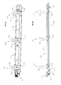
- FIG. 1A is a perspective view of an improved locking ring metal of the present invention having a vertically extending trigger, and FIG. 1B is an elevation view thereof;
- FIG. 2A is a perspective view of an improved locking ring metal of the present invention having a horizontally extending trigger, and FIG. 2B is an elevation view thereof;
- FIG. 3 is a view similar to FIG. 1B but in the ring metal open position
- FIG. 4 is a bottom plan view of the ring metal in its closed position
- FIG. 5 is a top plan view of the ring metal in its closed position
- FIG. 6 is an end view of the ring metal in its closed position
- FIG. 7 is an exploded view of the ring metal
- FIG. 8 is a perspective view of a vertically extending trigger installed in the ring metal
- FIG. 9 is a perspective view of a coil spring installed in the ring metal
- FIG. 10 is a perspective view of a travel bar installed in the ring metal
- FIG. 11 is an enlarged view of one end of the travel bar
- FIG. 12 is a perspective view of the underside of the ring metal
- FIG. 13 is a partial view of one end of the ring metal with one of the frames removed so to illustrate the position of the trigger and travel bar when the ring metal is closed;
- FIG. 14 is a view of an intermediate portion of the ring metal with one of the frames removed to further illustrate the position of the travel bar when the ring metal is closed;
- FIG. 15 is an enlarged view of one end of the ring metal illustrating the position of the trigger and travel bar when the ring metal is open;
- FIG. 16 is a perspective view of the underside of the ring metal when the ring metal is closed.
- FIG. 17 is a perspective view of the underside of the ring metal when the ring metal is open.
- a locking ring metal of the present invention for use in a ring binder (not shown) holding hole-punched sheets of paper and the like is indicated generally 10 in FIGS. 1A and 1B, and 10 ′ in FIGS. 2A and 2B .
- Ring metal 10 or 10 ′ is attached to the spine portion of the binder in a conventional manner using fasteners F.
- metal 10 or 10 ′ can be either of a metal or a plastic construction, or a combination of metal and plastic.
- metal 10 has a vertically extending trigger 11 installed at one end of it; while metal 10 ′ has a horizontally extending trigger 11 ′ installed at that end.
- the description which follows will be directed at metal 10 ; although, those skilled in the art will appreciate that the construction and operation of the invention can also be implemented with metal 10 ′.
- Ring metal 10 includes at least one, and preferably a plurality of binder rings. As shown in the drawings, ring metal 10 includes three spaced apart rings 12 , 14 , and 16 each of which is comprised of two complementary curved ring segments 12 a , 12 b , 14 a , 14 b , and 16 a , 16 b respectively.
- the rings 12 and 16 are located adjacent each end of the ring metal with ring 14 located approximately midway the length thereof.
- Each ring segment has one end attached to a hinge plate or frame 18 , 20 respectively.
- the frames are each a generally rectangular shaped plate and the frames extend side-by-side, parallel to each other, substantially the length of ring metal 10 .
- frames 18 , 20 are flexed. Movement of frames 18 , 20 in this regard causes the outer, mating ends of the respective rings to separate from each other and open the binder.
- ring metal 10 could have more or fewer rings than the rings 12 , 14 , 16 without departing from the scope of the invention.
- a post 21 P (see FIG. 15 ) is formed on the outer end of each ring half 12 a , 14 a , 16 a , and a socket 21 S (see FIG. 13 ) is formed in the outer end of the other ring half 12 b , 14 b , 16 b .
- This type of ring construction is commonly referred to as “gap free” in that the even if the outer ends of a ring start to pull apart, the post 21 P initially remains inserted in the socket 21 S so a gap does not form between the ends of the ring.
- Gap free ring metal constructions are known in the art. See, for example, U.S. Pat. No. 4,690,580 (the '580 patent) and D451,954. Since the gap free construction of ring metal 10 , 10 ′ is made in accordance with the teachings of the '580 U.S. patent, it will be not be described.
- each of the frames has cutout sections 18 a - 18 e and 20 a - 20 e formed along their inner reach.
- the corresponding sections on each frame are identical in size and shape with those in the other frame. These cutout sections are to accommodate installation of the frames in the ring metal assembly as well as facilitate opening and closing of the binder rings as described hereinafter.
- a cover, housing, or shield 22 extends the length of ring metal 10 .
- Frames 18 , 20 are installed within cover 22 and the cover has spaced openings 24 along each side through which the respective ring segments extend so to curve up and over the top of the housing.
- Shield 22 has a curved upper surface with flanks 22 a , 22 b that extend downwardly and inwardly from the sides of the shield.
- the outer edges of frames 18 , 20 extend along the length of cover 20 between the upper, curved top surface of the housing and flanks 22 a , 22 b of the housing.
- Posts F located at each end of the cover extend from the underside of the cover and are used for fastening ring metal 10 to the binder spine using rivets or the like, all as is well-known in the art.
- Trigger mechanism 11 is located at one end of ring metal 10 and is rotatably secured to the ring metal housing. Referring to FIG. 7 , respective brackets 26 extend downwardly from each side of cover 22 at the one end of the housing where trigger 11 is mounted to the housing. Each bracket has an opening 27 in its lower end. Trigger 11 has a generally vertical or finger pad section 11 a and a lower, horizontal section 11 b . A bore 28 extends through section 11 b and a pin 30 is inserted through this bore and the openings 27 in the respective brackets 26 to attach trigger 11 to the brackets and install the trigger to cover 22 . In operation, pushing against finger pad section 11 a of trigger 11 causes the trigger to rotate or pivot about pin 30 .
- Trigger section 11 b includes an upper horizontally extending projection 31 , and a lower horizontally extending projection or tongue 32 .
- Trigger 11 When trigger 11 is mounted to housing 22 , the ends of the frames 18 , 20 at the one end of ring metal 10 , are set between projection 31 and tongue 32 . This is as shown in FIG. 13 .
- a travel bar indicated generally 34 in the drawings is installed in ring metal 10 .
- travel bar 34 is not connected to trigger 11 , but rather overlays the frames 18 , 20 with its end adjacent the trigger spatially separated from the trigger as shown in FIG. 13 .
- the travel bar which extends substantially the length of housing 22 , is installed within the housing beneath the top surface of the cover, and above frames 18 , 20 so to overlay the frames.
- travel bar 34 moves toward trigger 11 even though the travel bar is not connected to the trigger.
- the end of travel bar 34 adjacent trigger 11 overlays projection 31 of the trigger as shown in FIG. 15 .
- travel bar 34 has a top 36 and side rails 38 extending beneath the top of the travel bar along each side thereof and extending the length of the travel bar.
- the width of travel bar 34 is greater than that of projection 31 of trigger 11 .
- the ends of the side rails adjacent trigger 11 are rounded as shown in FIGS. 10 and 11 .
- the travel bar Inwardly from this end of travel bar 34 , the travel bar as an oval shaped segment 40 which is open in its center. As shown in FIG. 13 , this allows travel bar 34 to move longitudinally of ring metal 10 about the upper end of the fastener F located at this end of the assembly.
- the travel bar has additional oval shaped openings 42 and 46 formed at spaced intervals along its length to accommodate movement of the travel bar back and forth underneath housing 22 , about the fastener F at the other end of the assembly, and protrusions on the underside of the top portion of the cover.
- the travel bar also has a rectangular shaped opening 44 formed approximately midway along its length for one end 47 of a coil spring 48 , which is mounted on travel bar 34 , to extend through top surface 36 of the travel bar and seat against a bracket 49 (see FIG. 14 ) formed on the underside of the top of cover 22 .
- spring 48 When spring 48 is mounted as shown in FIG. 14 , it biases travel bar 34 to move in the binder ring opening direction.
- At least one, and preferably a plurality of spaced blocking elements B are formed on the underside of travel bar 34 .
- Three blocking elements B are shown in the drawings.
- Each blocking element has an L shape including a base Bb which extends parallel to the travel bar and a vertical section By (see FIGS. 10 and 11 ) extending from the underside of the travel bar.
- the respective blocking elements B extend through the corresponding openings 18 b , 20 b , 18 d , 20 d , and 18 e , 20 e formed in frames 18 , 20 . These locations correspond to the locations of the rings 12 , 14 , and 16 when metal 10 is closed. As shown in FIG. 16 , when ring metal 10 is closed, the lower, base end of each blocking element B extends through these openings in frames 18 , 20 .
- a vertical plate 49 depends from the underside of the travel bar. Plate 49 is located midway along the length of travel bar 34 , but spaced from opening 44 in the travel bar as shown in FIG. 10 .
- a post 53 extends from the inner face of plate 49 which comprises the bracket for seating end 47 of coil spring 48 .
- the other end of coil spring 48 attaches to an L-shaped tab 51 formed on the underside of cover 22 (see FIG. 13 ) so to impart a bias force on the travel bar. Again, this bias force is in the direction to open, not close, ring metal 10 and the binder rings.
- each bracket 50 comprises identically formed segments on the underside of each frame 18 , 20 .
- the height of each bracket 50 is such that when ring metal 10 is closed, base Bb of the respective blocking elements B on travel bar 34 seats in one of the brackets. In this position, they are located on the underside of frames 18 , 20 and prevent any rotary movement of the frames. Accordingly, blocking elements B and brackets 50 comprise a co-operating means for effectively locking ring metal 10 in its closed position.
- each blocking element B moves with the travel bar.
- base Bb of each blocking element is drawn away from its associated bracket 50 .
- the blocking elements are drawn into the cutout sections 18 b , 18 d , 18 e of frame 18 , and the corresponding cutout sections 20 b , 20 d , 20 e of frame 20 .
- the base Bb of each blocking element B is completely withdrawn from its associated bracket 50 , they are also fully moved into the cutout sections of frames 18 , 20 . I.e., the blocking elements are no longer positioned under the frames. This is shown in FIG.
- the user can press the separated sections of one of the rings 12 , 14 , 16 back together.
- This movement pivots frames 18 , 20 back toward their original position.
- the underside of the frames push downwardly against tongue 32 of trigger 11 forcing the trigger back toward its original metal ring 10 closed position.
- This action further forces travel bar 34 to move in the direction away from trigger 11 to close the ring metal; which force is against the opening force provided by spring 48 .
- Continued movement of the travel bar moves the base portion of blocking elements B back toward their original positions in which they are again inserted into the space between the base of brackets 50 and the underside of frames 18 , 20 , locking the frames in the binder ring closed position.
Landscapes
- Sheet Holders (AREA)
Abstract
Description
Claims (20)
Priority Applications (2)
| Application Number | Priority Date | Filing Date | Title |
|---|---|---|---|
| US13/827,559 US9815315B2 (en) | 2012-11-19 | 2013-03-14 | Locking ring metal |
| US14/454,118 US9821594B2 (en) | 2012-11-19 | 2014-08-07 | Locking ring metal |
Applications Claiming Priority (2)
| Application Number | Priority Date | Filing Date | Title |
|---|---|---|---|
| US201261727944P | 2012-11-19 | 2012-11-19 | |
| US13/827,559 US9815315B2 (en) | 2012-11-19 | 2013-03-14 | Locking ring metal |
Related Child Applications (1)
| Application Number | Title | Priority Date | Filing Date |
|---|---|---|---|
| US14/454,118 Continuation-In-Part US9821594B2 (en) | 2012-11-19 | 2014-08-07 | Locking ring metal |
Publications (2)
| Publication Number | Publication Date |
|---|---|
| US20140140754A1 US20140140754A1 (en) | 2014-05-22 |
| US9815315B2 true US9815315B2 (en) | 2017-11-14 |
Family
ID=50728079
Family Applications (1)
| Application Number | Title | Priority Date | Filing Date |
|---|---|---|---|
| US13/827,559 Expired - Fee Related US9815315B2 (en) | 2012-11-19 | 2013-03-14 | Locking ring metal |
Country Status (2)
| Country | Link |
|---|---|
| US (1) | US9815315B2 (en) |
| CN (1) | CN103818149B (en) |
Families Citing this family (10)
| Publication number | Priority date | Publication date | Assignee | Title |
|---|---|---|---|---|
| US7731441B2 (en) | 2006-09-27 | 2010-06-08 | World Wide Stationery Mfg. Co., Ltd. | Ring binder mechanism |
| US8047737B2 (en) | 2006-09-27 | 2011-11-01 | World Wide Stationery Mfg. Co., Ltd. | Ring binder mechanism |
| CN102126374B (en) | 2010-01-14 | 2013-10-30 | 国际文具制造厂有限公司 | Ring Binder Mechanism with Dual Time Buffered Actuator |
| US9522561B2 (en) * | 2013-08-27 | 2016-12-20 | World Wide Stationery Mfg. Co., Ltd. | Ring binder mechanism |
| CA2932238C (en) * | 2013-10-04 | 2017-09-19 | Ccl Label, Inc. | Single booster binder mechanism |
| US9102187B1 (en) * | 2014-02-19 | 2015-08-11 | Chung Tin International, Inc. | Ring binder mechanism |
| CN203832042U (en) * | 2014-04-25 | 2014-09-17 | 钟家刿 | Automatic circulation clip |
| CN105365441A (en) * | 2014-08-07 | 2016-03-02 | 美国林·宾德有限公司 | Improved locking ring metal |
| JP6476804B2 (en) * | 2014-12-08 | 2019-03-06 | コクヨ株式会社 | Binding tool |
| CN110758884B (en) * | 2019-10-30 | 2020-12-22 | 范秀英 | Clinical thermometer storage device with ultraviolet disinfection function |
Citations (67)
| Publication number | Priority date | Publication date | Assignee | Title |
|---|---|---|---|---|
| US3097652A (en) * | 1959-09-03 | 1963-07-16 | Loose Leaf Metals Company | Transfer bar and locking mechanism |
| US5180247A (en) | 1991-05-06 | 1993-01-19 | World-Wide Stationery Manufacturing Co. Ltd. | Ring binder |
| US5354142A (en) | 1991-05-03 | 1994-10-11 | World Wide Stationery Manufacturing Company Limited | Ring binder |
| US5476335A (en) | 1995-03-31 | 1995-12-19 | U.S. Ring Binder Corp. | Locking mechanism for a ring binder |
| US5611633A (en) | 1996-06-27 | 1997-03-18 | Whaley; Paul | Ring binder assembly |
| US5816729A (en) | 1997-02-25 | 1998-10-06 | Us Ring Binder Corp. | Ring binder with low profile ring metal |
| US5924811A (en) | 1997-07-30 | 1999-07-20 | World Wide Stationery Mfg. Co., Ltd. | Assembling and disassembling device for ring binders |
| US5957611A (en) | 1997-08-12 | 1999-09-28 | U.S. Ring Binder Corporation | Ring binder with dual angle ring metal |
| US6062760A (en) | 1998-01-19 | 2000-05-16 | U.S. Ring Binder Corp. | Modular binder ring construction |
| US6270279B1 (en) | 2000-08-18 | 2001-08-07 | U.S. Ring Binder L.P. | Ring binder mechanism |
| US20030103798A1 (en) | 2001-11-30 | 2003-06-05 | World Wide Stationery Manufacturing Company, Ltd. | Ring binder mechanism |
| US20030103796A1 (en) | 2001-11-30 | 2003-06-05 | World Wide Stationery Manufacturing Company, Limited | Ring binder ring locking |
| US6749357B2 (en) | 2001-11-30 | 2004-06-15 | World Wide Stationery Manufacturing Company, Limited | Ring binder mechanism |
| US6840695B2 (en) | 2000-04-25 | 2005-01-11 | Esselte Leitz Gmbh & Co Kg | Ring-binder mechanism |
| US6916134B2 (en) | 2003-05-22 | 2005-07-12 | Hong Kong Stationery Manufacturing Co., Ltd. | Safety ring binder having sliding actuators |
| CA2493203A1 (en) | 2004-03-15 | 2005-09-15 | World Wide Stationery Manufacturing Company, Ltd. | Ready lock ring binder mechanism |
| US20050207826A1 (en) | 2004-03-15 | 2005-09-22 | World Wide Stationery Manufacturing Company, Limited | Soft close ring binder mechanism with mating ring tips |
| US20050271459A1 (en) | 2004-06-03 | 2005-12-08 | World Wide Stationery Mfg. Co., Ltd. | Interlocking ring tip formations for paired ring members of a ring binder mechanism |
| US6974273B2 (en) | 2002-07-16 | 2005-12-13 | World Wide Stationery Manufacturing Company Limited | Ring binder |
| US20060008318A1 (en) | 2004-07-07 | 2006-01-12 | World Wide Stationery Manufacturing Company Limited | Ring binder mechanism with reinforced hinge plates |
| CN1727206A (en) | 2004-07-27 | 2006-02-01 | 国际文具制造厂有限公司 | ring binder mechanism |
| US20060153630A1 (en) | 2005-01-11 | 2006-07-13 | World Wide Stationery Mfg. Co., Ltd. | Ring mechanism with collapsible ring members |
| US20070048077A1 (en) | 2005-08-31 | 2007-03-01 | World Wide Stationery Mfg. Co., Ltd. | Ring binder having a clip |
| US20070048071A1 (en) | 2005-08-31 | 2007-03-01 | World Wide Stationery Mfg. Co., Ltd. | Fastening system for a ring binder mechanism |
| US20070048072A1 (en) | 2005-08-29 | 2007-03-01 | World Wide Stationery Mfg. Co., Ltd. | Ring binder mechanism |
| US20070048079A1 (en) | 2005-08-31 | 2007-03-01 | World Wide Stationery Mfg. Co., Ltd. | Ring binder having a clip |
| US20070048080A1 (en) | 2005-08-31 | 2007-03-01 | World Wide Stationery Mfg. Co., Ltd. | Ring binder having a clip |
| US20070086836A1 (en) | 2005-09-19 | 2007-04-19 | World Wide Stationery Mfg. Co., Ltd. | Ring binder mechanism with operating lever and travel bar |
| CN1978214A (en) | 2005-12-09 | 2007-06-13 | 株式会社锦宫事务 | Binding apparatus of document |
| US20070134054A1 (en) * | 2005-12-08 | 2007-06-14 | Li Shan J | Ring binder mechanism |
| US20070140778A1 (en) | 2005-03-22 | 2007-06-21 | World Wide Stationery Mfg. Co., Ltd. | Lever for a Ring Binder Mechanism |
| US20070140780A1 (en) * | 2005-12-12 | 2007-06-21 | Staples The Office Superstore, Llc | Ring binder mechanism |
| US20070160415A1 (en) | 2005-03-22 | 2007-07-12 | World Wide Stationery Mfg. Co., Ltd. | Ring Binder Mechanism |
| US20070160416A1 (en) | 2004-03-15 | 2007-07-12 | World Wide Stationery Mfg. Co., Ltd. | Positive Lock Ring Binder Mechanism |
| US20070223990A1 (en) | 2006-03-24 | 2007-09-27 | World Wide Stationery Mfg. Co., Ltd. | Fastening System |
| US20080075527A1 (en) | 2006-09-27 | 2008-03-27 | World Wide Stationery Mfg. Co., Ltd. | Ring Binder Mechanism |
| US20080075526A1 (en) | 2006-09-27 | 2008-03-27 | World Wide Stationery Mfg. Co., Ltd. | Ring Binder Mechanism |
| US20080080926A1 (en) | 2006-09-28 | 2008-04-03 | World Wide Stationery Mfg. Co., Ltd. | Ring binder mechanism with sliding hinge plate |
| US20080080925A1 (en) | 2006-09-28 | 2008-04-03 | World Wide Stationery Mfg. Co., Ltd. | Ring Binder Mechanism with a Sliding Hinge Plate |
| US20080085145A1 (en) | 2006-09-27 | 2008-04-10 | World Wide Stationery Manufacturing Company Limited | Ring binder mechanism having plastic housing |
| US20080124166A1 (en) | 2006-09-27 | 2008-05-29 | World Wide Stationery Mfg. Co., Ltd. | Ring Binder Mechanism |
| US20080170905A1 (en) | 2007-01-15 | 2008-07-17 | World Wide Stationery Mfg. Co., Ltd. | Hangable Ring Mechanism |
| US20080175651A1 (en) | 2007-01-18 | 2008-07-24 | World Wide Stationery Mfg. Co., Ltd. | Ring Binder Mechanism with Transverse Actuator |
| US20080175652A1 (en) | 2007-01-18 | 2008-07-24 | World Wide Stationery Mfg. Co., Ltd. | Ring Binder Mechanism |
| US7404685B2 (en) | 2004-12-30 | 2008-07-29 | World Wide Stationery Manufacturing Company, Limited | Ring binder mechanism spring biased to a locked position when ring members close |
| US20080286035A1 (en) | 2007-05-16 | 2008-11-20 | World Wide Stationery Mfg. Co., Ltd. | Ring Binder Mechanism Having Blocking Device |
| US20080298883A1 (en) | 2007-05-29 | 2008-12-04 | World Wide Stationery Mfg. Co., Ltd. | Ring Binder Kit and Fastening System |
| US20090035053A1 (en) | 2007-07-30 | 2009-02-05 | World Wide Stationery Mfg. Co., Ltd. | Ring Binder Mechanism with Plastic Housing and Locking Structure |
| US20090041532A1 (en) | 2002-12-18 | 2009-02-12 | World Wide Stationery Mfg. Co., Ltd | Ready lock ring binder mechanism |
| US20090060631A1 (en) | 2007-08-31 | 2009-03-05 | World Wide Stationery Mfg. Co., Ltd. | Ring binder mechanism with polymeric housing and travel bar |
| US7513708B2 (en) | 2005-08-31 | 2009-04-07 | World Wide Stationery Mfg. Co., Ltd. | Ring binder mechanism having slide connector |
| US7524128B2 (en) | 2004-12-30 | 2009-04-28 | World Wide Stationery Manufacturing Company Limited | Ring binder mechanism spring biased to a locked position |
| US20090116896A1 (en) | 2007-11-07 | 2009-05-07 | World Wide Stationery Mfg. Co., Ltd. | Ring Binder Mechanism with Pen Holder |
| US7534064B2 (en) | 2005-01-12 | 2009-05-19 | World Wide Stationery Mfg. Co., Ltd. | Ring mechanism biased to closed and locked position |
| US20090285623A1 (en) | 2008-05-19 | 2009-11-19 | Paul Whaley | Locking ring metal |
| US20100003070A1 (en) | 2008-07-01 | 2010-01-07 | World Wide Stationery, Mfg. Co., Ltd. | Ring mechanism having fold-down rings |
| US7661898B2 (en) | 2004-03-15 | 2010-02-16 | World Wide Stationery Manufacturing Company, Limited | Soft close ring binder mechanism with reinforced travel bar |
| US7665926B2 (en) | 2005-05-06 | 2010-02-23 | World Wide Stationery Mfg. Co., Ltd. | Ring mechanism with spring biased travel bar |
| US7674062B2 (en) | 2005-04-12 | 2010-03-09 | Hans Johann Horn | Ring binder mechanism |
| US20100166490A1 (en) | 2008-12-30 | 2010-07-01 | World Wide Stationery, Mfg. Co., Ltd. | Actuator for a ring binder mechanism |
| US7748922B2 (en) | 2004-03-15 | 2010-07-06 | World Wide Stationery Manufacturing Company, Limited | Ring binder mechanism with dual pivot locking elements |
| US20110170942A1 (en) * | 2010-01-14 | 2011-07-14 | World Wide Stationery Mfg. Co., Ltd. | Ring binder mechanism having dual time buffer actuator |
| US8002488B2 (en) | 2004-03-15 | 2011-08-23 | World Wide Stationery Mfg. Co., Ltd. | Soft close ring binder mechanism |
| US20110305500A1 (en) | 2010-06-09 | 2011-12-15 | World Wide Stationery Manufacturing Co., Ltd. | Ring binder mechanism having unitary structure |
| US8186889B2 (en) | 2007-03-30 | 2012-05-29 | Hitachi Chemical Co., Ltd. | Optical connecting member and display apparatus |
| US8393819B2 (en) | 2010-11-12 | 2013-03-12 | Moore Wallace North America, Inc. | Binder apparatus |
| US20130061447A1 (en) | 2010-09-30 | 2013-03-14 | Samsill Corporation | Method of Providing a Spine Label Pocket on a Binding Cover |
-
2013
- 2013-03-14 US US13/827,559 patent/US9815315B2/en not_active Expired - Fee Related
- 2013-03-29 CN CN201310122561.4A patent/CN103818149B/en not_active Expired - Fee Related
Patent Citations (108)
| Publication number | Priority date | Publication date | Assignee | Title |
|---|---|---|---|---|
| US3097652A (en) * | 1959-09-03 | 1963-07-16 | Loose Leaf Metals Company | Transfer bar and locking mechanism |
| US5354142A (en) | 1991-05-03 | 1994-10-11 | World Wide Stationery Manufacturing Company Limited | Ring binder |
| US5180247A (en) | 1991-05-06 | 1993-01-19 | World-Wide Stationery Manufacturing Co. Ltd. | Ring binder |
| US5476335A (en) | 1995-03-31 | 1995-12-19 | U.S. Ring Binder Corp. | Locking mechanism for a ring binder |
| US5611633A (en) | 1996-06-27 | 1997-03-18 | Whaley; Paul | Ring binder assembly |
| US5816729A (en) | 1997-02-25 | 1998-10-06 | Us Ring Binder Corp. | Ring binder with low profile ring metal |
| US5924811A (en) | 1997-07-30 | 1999-07-20 | World Wide Stationery Mfg. Co., Ltd. | Assembling and disassembling device for ring binders |
| US5957611A (en) | 1997-08-12 | 1999-09-28 | U.S. Ring Binder Corporation | Ring binder with dual angle ring metal |
| US6062760A (en) | 1998-01-19 | 2000-05-16 | U.S. Ring Binder Corp. | Modular binder ring construction |
| US6840695B2 (en) | 2000-04-25 | 2005-01-11 | Esselte Leitz Gmbh & Co Kg | Ring-binder mechanism |
| US6270279B1 (en) | 2000-08-18 | 2001-08-07 | U.S. Ring Binder L.P. | Ring binder mechanism |
| US6749357B2 (en) | 2001-11-30 | 2004-06-15 | World Wide Stationery Manufacturing Company, Limited | Ring binder mechanism |
| US20030103796A1 (en) | 2001-11-30 | 2003-06-05 | World Wide Stationery Manufacturing Company, Limited | Ring binder ring locking |
| US20030103798A1 (en) | 2001-11-30 | 2003-06-05 | World Wide Stationery Manufacturing Company, Ltd. | Ring binder mechanism |
| US20110085846A1 (en) | 2001-11-30 | 2011-04-14 | World Wide Stationery Mfg. Co., Ltd. | Ring Binder Mechanism |
| US7878729B2 (en) | 2001-11-30 | 2011-02-01 | World Wide Stationery Manufacturing Company, Ltd. | Intermediate connector for a ring binder mechanism |
| US20080050171A1 (en) | 2001-11-30 | 2008-02-28 | World Wide Stationery Mfg. Co., Ltd. | Ring binder mechanism |
| US6974273B2 (en) | 2002-07-16 | 2005-12-13 | World Wide Stationery Manufacturing Company Limited | Ring binder |
| US7549817B2 (en) | 2002-12-18 | 2009-06-23 | World Wide Stationery Mfg. Co., Ltd. | Ready lock ring binder mechanism |
| US7744300B2 (en) | 2002-12-18 | 2010-06-29 | World Wide Stationery Mfg. Co., Ltd. | Ready lock ring binder mechanism |
| US20090041532A1 (en) | 2002-12-18 | 2009-02-12 | World Wide Stationery Mfg. Co., Ltd | Ready lock ring binder mechanism |
| US7891901B2 (en) | 2002-12-18 | 2011-02-22 | World Wide Stationery Mfg. Co., Ltd. | Ready lock ring binder mechanism |
| US8038361B2 (en) | 2002-12-18 | 2011-10-18 | World Wide Stationery Mfg. Co., Ltd. | Ready lock ring binder mechanism |
| US20110110703A1 (en) * | 2002-12-18 | 2011-05-12 | World Wide Stationery Mfg. Co., Ltd. | Ready lock ring binder mechanism |
| US6916134B2 (en) | 2003-05-22 | 2005-07-12 | Hong Kong Stationery Manufacturing Co., Ltd. | Safety ring binder having sliding actuators |
| US7748922B2 (en) | 2004-03-15 | 2010-07-06 | World Wide Stationery Manufacturing Company, Limited | Ring binder mechanism with dual pivot locking elements |
| US20070160416A1 (en) | 2004-03-15 | 2007-07-12 | World Wide Stationery Mfg. Co., Ltd. | Positive Lock Ring Binder Mechanism |
| CA2493203A1 (en) | 2004-03-15 | 2005-09-15 | World Wide Stationery Manufacturing Company, Ltd. | Ready lock ring binder mechanism |
| US8002488B2 (en) | 2004-03-15 | 2011-08-23 | World Wide Stationery Mfg. Co., Ltd. | Soft close ring binder mechanism |
| US20050207826A1 (en) | 2004-03-15 | 2005-09-22 | World Wide Stationery Manufacturing Company, Limited | Soft close ring binder mechanism with mating ring tips |
| US7661898B2 (en) | 2004-03-15 | 2010-02-16 | World Wide Stationery Manufacturing Company, Limited | Soft close ring binder mechanism with reinforced travel bar |
| CN1709711A (en) | 2004-03-15 | 2005-12-21 | 国际文具制造厂有限公司 | Quick-lock ring binder mechanism |
| US7597498B2 (en) | 2004-03-15 | 2009-10-06 | World Wide Stationery Mfg. Co., Ltd. | Positive lock ring binder mechanism |
| US20050271459A1 (en) | 2004-06-03 | 2005-12-08 | World Wide Stationery Mfg. Co., Ltd. | Interlocking ring tip formations for paired ring members of a ring binder mechanism |
| US20060008318A1 (en) | 2004-07-07 | 2006-01-12 | World Wide Stationery Manufacturing Company Limited | Ring binder mechanism with reinforced hinge plates |
| US20060024124A1 (en) * | 2004-07-27 | 2006-02-02 | World Wide Stationery Mfg. Co., Ltd. | Ring binder mechanism |
| US20070140779A1 (en) | 2004-07-27 | 2007-06-21 | World Wide Stationery Mfg. Co., Ltd. | Ring Binder Mechanism |
| US20070283542A1 (en) | 2004-07-27 | 2007-12-13 | World Wide Stationery Mfg. Co., Ltd. | Method of Manufacturing a Ring Mechanism |
| CN1727206A (en) | 2004-07-27 | 2006-02-01 | 国际文具制造厂有限公司 | ring binder mechanism |
| US20100278583A1 (en) | 2004-12-30 | 2010-11-04 | World Wide Stationery Mfg. Co., Ltd. | Ring binder mechanism |
| US20080267691A1 (en) | 2004-12-30 | 2008-10-30 | World Wide Stationery Mfg. Co., Ltd. | Ring binder mechanism |
| US7762734B2 (en) | 2004-12-30 | 2010-07-27 | World Wide Stationery Mfg. Co., Ltd. | Ring binder mechanism |
| US8043018B2 (en) | 2004-12-30 | 2011-10-25 | World Wide Stationery Manufacturing Co., Ltd. | Ring binder mechanism |
| US7524128B2 (en) | 2004-12-30 | 2009-04-28 | World Wide Stationery Manufacturing Company Limited | Ring binder mechanism spring biased to a locked position |
| US7404685B2 (en) | 2004-12-30 | 2008-07-29 | World Wide Stationery Manufacturing Company, Limited | Ring binder mechanism spring biased to a locked position when ring members close |
| US20060153630A1 (en) | 2005-01-11 | 2006-07-13 | World Wide Stationery Mfg. Co., Ltd. | Ring mechanism with collapsible ring members |
| US7758271B2 (en) | 2005-01-12 | 2010-07-20 | World Wide Stationery Mfg. Co., Ltd. | Ring mechanism biased to closed and locked position |
| US20090169287A1 (en) | 2005-01-12 | 2009-07-02 | World Wide Stationery Mfg. Co., Ltd. | Ring mechanism biased to closed and locked position |
| US7534064B2 (en) | 2005-01-12 | 2009-05-19 | World Wide Stationery Mfg. Co., Ltd. | Ring mechanism biased to closed and locked position |
| US20100054850A1 (en) | 2005-03-22 | 2010-03-04 | World Wide Stationery Mfg. Co., Ltd. | Lever for a ring binder mechanism |
| US7726897B2 (en) | 2005-03-22 | 2010-06-01 | World Wide Stationery Mfg. Co., Ltd. | Ring binder mechanism |
| US20100166491A1 (en) | 2005-03-22 | 2010-07-01 | World Wide Stationery Mfg. Co., Ltd. | Lever for a ring binder mechanism |
| US20070160415A1 (en) | 2005-03-22 | 2007-07-12 | World Wide Stationery Mfg. Co., Ltd. | Ring Binder Mechanism |
| US7661899B2 (en) | 2005-03-22 | 2010-02-16 | World Wide Stationery Mfg. Co., Ltd. | Lever for a ring binder mechanism |
| US20070140778A1 (en) | 2005-03-22 | 2007-06-21 | World Wide Stationery Mfg. Co., Ltd. | Lever for a Ring Binder Mechanism |
| US7950867B2 (en) | 2005-03-22 | 2011-05-31 | World Wide Stationery Mfg. Co., Ltd. | Lever for a ring binder mechanism |
| US7674062B2 (en) | 2005-04-12 | 2010-03-09 | Hans Johann Horn | Ring binder mechanism |
| US7665926B2 (en) | 2005-05-06 | 2010-02-23 | World Wide Stationery Mfg. Co., Ltd. | Ring mechanism with spring biased travel bar |
| US20070048072A1 (en) | 2005-08-29 | 2007-03-01 | World Wide Stationery Mfg. Co., Ltd. | Ring binder mechanism |
| US20070048071A1 (en) | 2005-08-31 | 2007-03-01 | World Wide Stationery Mfg. Co., Ltd. | Fastening system for a ring binder mechanism |
| US7513708B2 (en) | 2005-08-31 | 2009-04-07 | World Wide Stationery Mfg. Co., Ltd. | Ring binder mechanism having slide connector |
| US20070048077A1 (en) | 2005-08-31 | 2007-03-01 | World Wide Stationery Mfg. Co., Ltd. | Ring binder having a clip |
| US20070048078A1 (en) | 2005-08-31 | 2007-03-01 | World Wide Stationery Mfg. Co., Ltd. | Ring binder having a clip |
| US20070048079A1 (en) | 2005-08-31 | 2007-03-01 | World Wide Stationery Mfg. Co., Ltd. | Ring binder having a clip |
| US20070048080A1 (en) | 2005-08-31 | 2007-03-01 | World Wide Stationery Mfg. Co., Ltd. | Ring binder having a clip |
| US20070086836A1 (en) | 2005-09-19 | 2007-04-19 | World Wide Stationery Mfg. Co., Ltd. | Ring binder mechanism with operating lever and travel bar |
| US20070134054A1 (en) * | 2005-12-08 | 2007-06-14 | Li Shan J | Ring binder mechanism |
| CN1978214A (en) | 2005-12-09 | 2007-06-13 | 株式会社锦宫事务 | Binding apparatus of document |
| US20070134053A1 (en) * | 2005-12-09 | 2007-06-14 | King Jim Co., Ltd. | Binding tool for documents or the like |
| US20070140780A1 (en) * | 2005-12-12 | 2007-06-21 | Staples The Office Superstore, Llc | Ring binder mechanism |
| US20070223990A1 (en) | 2006-03-24 | 2007-09-27 | World Wide Stationery Mfg. Co., Ltd. | Fastening System |
| US8047737B2 (en) | 2006-09-27 | 2011-11-01 | World Wide Stationery Mfg. Co., Ltd. | Ring binder mechanism |
| US20080075527A1 (en) | 2006-09-27 | 2008-03-27 | World Wide Stationery Mfg. Co., Ltd. | Ring Binder Mechanism |
| US20120230755A1 (en) | 2006-09-27 | 2012-09-13 | World Wide Stationery Mfg. Co., Ltd. | Ring binder mechanism |
| US20120051830A1 (en) | 2006-09-27 | 2012-03-01 | World Wide Stationery Mfg. Co., Ltd. | Ring binder mechanism |
| US8052343B2 (en) | 2006-09-27 | 2011-11-08 | World Wide Stationery Mfg. Co., Ltd. | Ring binder mechanism |
| US20080124166A1 (en) | 2006-09-27 | 2008-05-29 | World Wide Stationery Mfg. Co., Ltd. | Ring Binder Mechanism |
| US20080085145A1 (en) | 2006-09-27 | 2008-04-10 | World Wide Stationery Manufacturing Company Limited | Ring binder mechanism having plastic housing |
| US7731441B2 (en) | 2006-09-27 | 2010-06-08 | World Wide Stationery Mfg. Co., Ltd. | Ring binder mechanism |
| US20090274508A1 (en) | 2006-09-27 | 2009-11-05 | World Wide Stationery Mfg. Co., Ltd. | Ring binder mechanism |
| US7648302B2 (en) | 2006-09-27 | 2010-01-19 | World Wide Stationery Mfg. Co., Ltd. | Ring binder mechanism |
| US20100232867A1 (en) | 2006-09-27 | 2010-09-16 | World Wide Stationery Mfg. Co., Ltd. | Ring binder mechanism |
| US20080075526A1 (en) | 2006-09-27 | 2008-03-27 | World Wide Stationery Mfg. Co., Ltd. | Ring Binder Mechanism |
| US20090274509A1 (en) | 2006-09-28 | 2009-11-05 | World Wide Stationery Mfg. Co., Ltd. | Ring binder mechanism with sliding hinge plate |
| US7600939B2 (en) | 2006-09-28 | 2009-10-13 | World Wide Stationery Mfg. Co., Ltd. | Ring binder mechanism with sliding hinge plate |
| US20080080926A1 (en) | 2006-09-28 | 2008-04-03 | World Wide Stationery Mfg. Co., Ltd. | Ring binder mechanism with sliding hinge plate |
| US20080080925A1 (en) | 2006-09-28 | 2008-04-03 | World Wide Stationery Mfg. Co., Ltd. | Ring Binder Mechanism with a Sliding Hinge Plate |
| US20080170905A1 (en) | 2007-01-15 | 2008-07-17 | World Wide Stationery Mfg. Co., Ltd. | Hangable Ring Mechanism |
| US20080175652A1 (en) | 2007-01-18 | 2008-07-24 | World Wide Stationery Mfg. Co., Ltd. | Ring Binder Mechanism |
| US20080175651A1 (en) | 2007-01-18 | 2008-07-24 | World Wide Stationery Mfg. Co., Ltd. | Ring Binder Mechanism with Transverse Actuator |
| US8186889B2 (en) | 2007-03-30 | 2012-05-29 | Hitachi Chemical Co., Ltd. | Optical connecting member and display apparatus |
| US20080286035A1 (en) | 2007-05-16 | 2008-11-20 | World Wide Stationery Mfg. Co., Ltd. | Ring Binder Mechanism Having Blocking Device |
| US7654764B2 (en) | 2007-05-16 | 2010-02-02 | World Wide Stationery Mfg. Co. Ltd. | Ring binder mechanism having blocking device |
| US20080298883A1 (en) | 2007-05-29 | 2008-12-04 | World Wide Stationery Mfg. Co., Ltd. | Ring Binder Kit and Fastening System |
| US20090035053A1 (en) | 2007-07-30 | 2009-02-05 | World Wide Stationery Mfg. Co., Ltd. | Ring Binder Mechanism with Plastic Housing and Locking Structure |
| US20090060631A1 (en) | 2007-08-31 | 2009-03-05 | World Wide Stationery Mfg. Co., Ltd. | Ring binder mechanism with polymeric housing and travel bar |
| US20090116896A1 (en) | 2007-11-07 | 2009-05-07 | World Wide Stationery Mfg. Co., Ltd. | Ring Binder Mechanism with Pen Holder |
| US20090285623A1 (en) | 2008-05-19 | 2009-11-19 | Paul Whaley | Locking ring metal |
| US20100003070A1 (en) | 2008-07-01 | 2010-01-07 | World Wide Stationery, Mfg. Co., Ltd. | Ring mechanism having fold-down rings |
| US8162556B2 (en) | 2008-12-30 | 2012-04-24 | World Wide Stationery Mfg. Co., Ltd. | Actuator for a ring binder mechanism |
| US20100166490A1 (en) | 2008-12-30 | 2010-07-01 | World Wide Stationery, Mfg. Co., Ltd. | Actuator for a ring binder mechanism |
| US20110170942A1 (en) * | 2010-01-14 | 2011-07-14 | World Wide Stationery Mfg. Co., Ltd. | Ring binder mechanism having dual time buffer actuator |
| US20110311301A1 (en) | 2010-06-09 | 2011-12-22 | World Wide Stationery Manufacturing Co., Ltd. | Ring binder mechanism having retaining system on ring members |
| US20110311302A1 (en) | 2010-06-09 | 2011-12-22 | World Wide Stationery Manufacturing Co., Ltd. | Ring binder mechanism having snap-in ring members |
| US20110311300A1 (en) | 2010-06-09 | 2011-12-22 | World Wide Stationery Manufacturing Co., Ltd. | Ring binder mechanism having unitary structure |
| US20110305500A1 (en) | 2010-06-09 | 2011-12-15 | World Wide Stationery Manufacturing Co., Ltd. | Ring binder mechanism having unitary structure |
| US20130061447A1 (en) | 2010-09-30 | 2013-03-14 | Samsill Corporation | Method of Providing a Spine Label Pocket on a Binding Cover |
| US8393819B2 (en) | 2010-11-12 | 2013-03-12 | Moore Wallace North America, Inc. | Binder apparatus |
Also Published As
| Publication number | Publication date |
|---|---|
| CN103818149B (en) | 2017-05-03 |
| CN103818149A (en) | 2014-05-28 |
| US20140140754A1 (en) | 2014-05-22 |
Similar Documents
| Publication | Publication Date | Title |
|---|---|---|
| US9815315B2 (en) | Locking ring metal | |
| US9821594B2 (en) | Locking ring metal | |
| US3098490A (en) | Loose leaf ring binder | |
| US8002488B2 (en) | Soft close ring binder mechanism | |
| CN101376310B (en) | Ring binder mechanism with plastic material housing and travel lever | |
| US7665926B2 (en) | Ring mechanism with spring biased travel bar | |
| US7661898B2 (en) | Soft close ring binder mechanism with reinforced travel bar | |
| US5354142A (en) | Ring binder | |
| US20070086836A1 (en) | Ring binder mechanism with operating lever and travel bar | |
| US2552076A (en) | Loose-leaf binder | |
| US20060088364A1 (en) | Easy open ring binder | |
| US20090285623A1 (en) | Locking ring metal | |
| US440278A (en) | Sample-case | |
| JP6713725B2 (en) | Window stay | |
| US5967690A (en) | Loose-leaf binder | |
| US20150104237A1 (en) | Low-profile ring binder mechanism | |
| US7758273B2 (en) | Binding device for files and binders | |
| US450870A (en) | Bag-fastening | |
| JP2015077789A (en) | Low profile ring binder mechanism | |
| US1473247A (en) | Quick-release means for loose-leaf books | |
| ZA200708073B (en) | Lever-arch type file mechanism | |
| US1189258A (en) | Coin-bank. | |
| US20070048072A1 (en) | Ring binder mechanism | |
| US954735A (en) | Bag-fastener. | |
| US468235A (en) | Edwin l |
Legal Events
| Date | Code | Title | Description |
|---|---|---|---|
| AS | Assignment |
Owner name: U.S. RING BINDER, L.P., MISSOURI Free format text: ASSIGNMENT OF ASSIGNORS INTEREST;ASSIGNOR:WHALEY, PAUL;REEL/FRAME:030578/0706 Effective date: 20130610 |
|
| STCF | Information on status: patent grant |
Free format text: PATENTED CASE |
|
| FEPP | Fee payment procedure |
Free format text: MAINTENANCE FEE REMINDER MAILED (ORIGINAL EVENT CODE: REM.); ENTITY STATUS OF PATENT OWNER: SMALL ENTITY |
|
| LAPS | Lapse for failure to pay maintenance fees |
Free format text: PATENT EXPIRED FOR FAILURE TO PAY MAINTENANCE FEES (ORIGINAL EVENT CODE: EXP.); ENTITY STATUS OF PATENT OWNER: SMALL ENTITY |
|
| STCH | Information on status: patent discontinuation |
Free format text: PATENT EXPIRED DUE TO NONPAYMENT OF MAINTENANCE FEES UNDER 37 CFR 1.362 |
|
| FP | Lapsed due to failure to pay maintenance fee |
Effective date: 20211114 |