US9815238B2 - Blown film with integral profiles - Google Patents
Blown film with integral profiles Download PDFInfo
- Publication number
- US9815238B2 US9815238B2 US14/788,274 US201514788274A US9815238B2 US 9815238 B2 US9815238 B2 US 9815238B2 US 201514788274 A US201514788274 A US 201514788274A US 9815238 B2 US9815238 B2 US 9815238B2
- Authority
- US
- United States
- Prior art keywords
- cooling
- tube
- film
- extrusion
- extruded
- Prior art date
- Legal status (The legal status is an assumption and is not a legal conclusion. Google has not performed a legal analysis and makes no representation as to the accuracy of the status listed.)
- Active, expires
Links
Images


Classifications
-
- B29C47/8835—
-
- B—PERFORMING OPERATIONS; TRANSPORTING
- B29—WORKING OF PLASTICS; WORKING OF SUBSTANCES IN A PLASTIC STATE IN GENERAL
- B29C—SHAPING OR JOINING OF PLASTICS; SHAPING OF MATERIAL IN A PLASTIC STATE, NOT OTHERWISE PROVIDED FOR; AFTER-TREATMENT OF THE SHAPED PRODUCTS, e.g. REPAIRING
- B29C48/00—Extrusion moulding, i.e. expressing the moulding material through a die or nozzle which imparts the desired form; Apparatus therefor
- B29C48/25—Component parts, details or accessories; Auxiliary operations
- B29C48/88—Thermal treatment of the stream of extruded material, e.g. cooling
- B29C48/885—External treatment, e.g. by using air rings for cooling tubular films
-
- B29C47/0026—
-
- B29C47/883—
-
- B—PERFORMING OPERATIONS; TRANSPORTING
- B29—WORKING OF PLASTICS; WORKING OF SUBSTANCES IN A PLASTIC STATE IN GENERAL
- B29C—SHAPING OR JOINING OF PLASTICS; SHAPING OF MATERIAL IN A PLASTIC STATE, NOT OTHERWISE PROVIDED FOR; AFTER-TREATMENT OF THE SHAPED PRODUCTS, e.g. REPAIRING
- B29C48/00—Extrusion moulding, i.e. expressing the moulding material through a die or nozzle which imparts the desired form; Apparatus therefor
- B29C48/03—Extrusion moulding, i.e. expressing the moulding material through a die or nozzle which imparts the desired form; Apparatus therefor characterised by the shape of the extruded material at extrusion
- B29C48/09—Articles with cross-sections having partially or fully enclosed cavities, e.g. pipes or channels
- B29C48/10—Articles with cross-sections having partially or fully enclosed cavities, e.g. pipes or channels flexible, e.g. blown foils
-
- B—PERFORMING OPERATIONS; TRANSPORTING
- B29—WORKING OF PLASTICS; WORKING OF SUBSTANCES IN A PLASTIC STATE IN GENERAL
- B29C—SHAPING OR JOINING OF PLASTICS; SHAPING OF MATERIAL IN A PLASTIC STATE, NOT OTHERWISE PROVIDED FOR; AFTER-TREATMENT OF THE SHAPED PRODUCTS, e.g. REPAIRING
- B29C48/00—Extrusion moulding, i.e. expressing the moulding material through a die or nozzle which imparts the desired form; Apparatus therefor
- B29C48/25—Component parts, details or accessories; Auxiliary operations
- B29C48/88—Thermal treatment of the stream of extruded material, e.g. cooling
- B29C48/89—Internal treatment, e.g. by applying an internal cooling fluid stream
-
- B—PERFORMING OPERATIONS; TRANSPORTING
- B29—WORKING OF PLASTICS; WORKING OF SUBSTANCES IN A PLASTIC STATE IN GENERAL
- B29C—SHAPING OR JOINING OF PLASTICS; SHAPING OF MATERIAL IN A PLASTIC STATE, NOT OTHERWISE PROVIDED FOR; AFTER-TREATMENT OF THE SHAPED PRODUCTS, e.g. REPAIRING
- B29C48/00—Extrusion moulding, i.e. expressing the moulding material through a die or nozzle which imparts the desired form; Apparatus therefor
- B29C48/25—Component parts, details or accessories; Auxiliary operations
- B29C48/88—Thermal treatment of the stream of extruded material, e.g. cooling
- B29C48/911—Cooling
- B29C48/9115—Cooling of hollow articles
- B29C48/912—Cooling of hollow articles of tubular films
-
- B29C47/003—
-
- B29C47/0057—
-
- B—PERFORMING OPERATIONS; TRANSPORTING
- B29—WORKING OF PLASTICS; WORKING OF SUBSTANCES IN A PLASTIC STATE IN GENERAL
- B29C—SHAPING OR JOINING OF PLASTICS; SHAPING OF MATERIAL IN A PLASTIC STATE, NOT OTHERWISE PROVIDED FOR; AFTER-TREATMENT OF THE SHAPED PRODUCTS, e.g. REPAIRING
- B29C48/00—Extrusion moulding, i.e. expressing the moulding material through a die or nozzle which imparts the desired form; Apparatus therefor
- B29C48/001—Combinations of extrusion moulding with other shaping operations
- B29C48/0018—Combinations of extrusion moulding with other shaping operations combined with shaping by orienting, stretching or shrinking, e.g. film blowing
-
- B—PERFORMING OPERATIONS; TRANSPORTING
- B29—WORKING OF PLASTICS; WORKING OF SUBSTANCES IN A PLASTIC STATE IN GENERAL
- B29C—SHAPING OR JOINING OF PLASTICS; SHAPING OF MATERIAL IN A PLASTIC STATE, NOT OTHERWISE PROVIDED FOR; AFTER-TREATMENT OF THE SHAPED PRODUCTS, e.g. REPAIRING
- B29C48/00—Extrusion moulding, i.e. expressing the moulding material through a die or nozzle which imparts the desired form; Apparatus therefor
- B29C48/03—Extrusion moulding, i.e. expressing the moulding material through a die or nozzle which imparts the desired form; Apparatus therefor characterised by the shape of the extruded material at extrusion
- B29C48/12—Articles with an irregular circumference when viewed in cross-section, e.g. window profiles
-
- B—PERFORMING OPERATIONS; TRANSPORTING
- B29—WORKING OF PLASTICS; WORKING OF SUBSTANCES IN A PLASTIC STATE IN GENERAL
- B29K—INDEXING SCHEME ASSOCIATED WITH SUBCLASSES B29B, B29C OR B29D, RELATING TO MOULDING MATERIALS OR TO MATERIALS FOR MOULDS, REINFORCEMENTS, FILLERS OR PREFORMED PARTS, e.g. INSERTS
- B29K2023/00—Use of polyalkenes or derivatives thereof as moulding material
- B29K2023/04—Polymers of ethylene
-
- B—PERFORMING OPERATIONS; TRANSPORTING
- B29—WORKING OF PLASTICS; WORKING OF SUBSTANCES IN A PLASTIC STATE IN GENERAL
- B29L—INDEXING SCHEME ASSOCIATED WITH SUBCLASS B29C, RELATING TO PARTICULAR ARTICLES
- B29L2007/00—Flat articles, e.g. films or sheets
Definitions
- the present invention generally relates to blown films having integral profiles such as for bags and packaging.
- Plastic bags having zippers and used for storing food and other items present unique manufacturing challenges because they have so-called “integral profiles” which are sections of the bag films which are thicker than other sections of the bag films.
- Zipper bags are generally manufactured by ether separately forming a bag body and zipper profile and appending the zipper profile to the bag body or forming the bag body and zipper profile together in one process. Extrusion is one method of forming a bag body and zipper profile in a single process. When a bag body and zipper profile are extruded together in the same process, the thicker sections that define the zipper profile cool more slowly than the thinner sections that define the bag body.
- the differential cooling rates impart stresses and can result in distortion of the profile shapes. Also, slower cooling rates can permit relaxation of shape which manifests itself as distortion.
- slower cooling segments In order to maintain dimensional integrity of the thicker profile, slower cooling segments, as a general proposition it is necessary to use slow forming speeds so that the thicker profile sections are sufficiently hardened before the films are collapsed to minimize damage and distortion.
- U.S. Pat. No. 3,875,281 describes generally some of the challenges in manufacturing blown films with integral profiles, such as distortion, closing of gaps, and manufacturing speed.
- the '281 patent proposes to address differential profile cooling challenges by establishing two control zones. Zone 1 is a region between the die head and the frost line and zone 2 is the region above the frost line. In zone 1 , air is moved rapidly along the sides of the film to create a venturi effect to lower the atmospheric pressure. The arrangement requires a lower air ring 38 and shield 48 , and in fact profiles were unsatisfactory in the absence of shield 48 .
- the invention is directed to an improved process and apparatus for manufacturing blown films having integral profiles such as zippers in plastic bag films which process and apparatus manifest high speed, simplicity, reliability, and integrity of profile dimensions.
- a method for manufacturing a blown plastic film having integral profiles using an extruder comprises extruding a tube of polyethylene-based resin including at least two thickened profile sections extending continuously in the direction of extrusion along a surface of the tube. Each thickened profile section is preferentially cooled by directing a jet of cooling gas toward each thickened profile section.
- the extruded tube defines a bubble extending from an extrusion die head at a bottom of the bubble to a film collector at a top of the bubble.
- an extrusion system comprises an extruder configured to extrude a plastic material in an extrusion direction.
- An extrusion die defines an extrusion passage having a least one thin segment and at least one thick segment.
- the extrusion die is operatively connected to the extruder to receive the plastic material therefrom such that the extruded plastic material passes through the extrusion passage.
- the extrusion passage is configured to shape the plastic material into a film tube having a thickened profile section aligned with the thick segment of the extrusion passage.
- a freezing control device is positioned relative to the extrusion die to be received in an interior of the film tube as the film tube is being extruded.
- the freezing control device comprise a cooling jet configured to deliver the cooling gas toward the thickened profile section of the film tube as the film tube is being extruded and thereby preferentially cool the thickened profile section.
- FIG. 1 is a fragmentary cross section of a zipper profile of a bag
- FIG. 2 is a schematic diagram of an extrusion system
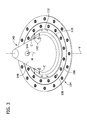
- FIG. 3 is a perspective of a freezing control device for use with the extrusion system.
- FIG. 4 is a perspective of another embodiment of a freezing control device for use with the extrusion system.
- the present disclosure is directed to systems and methods for manufacturing a blown plastic film having integral profiles.
- a sealable plastic bag generally indicated at reference number 10 , such as for food storage, specimen storage, or other storage wherein the bag has a zipper.
- Other types of blown plastic film with thickened profile sections can also be manufactured with the systems and methods described below without departing from the scope of the invention.
- the systems and methods described herein enable the extrusion of a blown plastic film with one or more thickened profile sections at a relatively high extrusion speed and while maintaining the desired integrity of the shape of the thickened profile sections.
- the bag 10 illustrated in FIG. 1 , is an example of one blown plastic film structure having a plurality of thickened profile sections.
- the bag 10 includes two primary bag panels 12 , 14 and a zipper 30 adapted to selectively close the bag 10 .
- the interlocking components of the zipper 30 have a thicker profile than the film that constitutes the side walls 12 , 14 , of the bag 10 .
- the bag includes zipper components 30 a , 30 b and gripper ribs 36 which form thickened profile sections of the bag. It will be understood that other embodiments of a bag or other film will have thickened profile sections of other shapes without departing from the scope of the invention.
- the bag panels 12 , 14 and thickened profile sections 30 a , 30 b , 36 can be extruded together such that the thickened profile sections extend continuously in the direction of extrusion along a surface of a tube, which is further processed to form the bag 10 .
- the zipper components 30 a and 30 b and gripper ribs 36 in FIG. 1 are examples of such thickened profile sections, wherein the thickened profile sections are co-extruded with a tube that eventually forms panels 12 , 14 .
- the invention is performed using an extrusion system 100 as shown schematically in FIG. 2 which has an extruder 102 in which polymer is melted and pumped into a tubular die 104 through which it is extruded.
- the die 104 defines a die passage, which defines the cross-sectional shape of the film as it exits the die.
- the die 104 includes a die head 106 , which defines the die passage 108 .
- dies 104 and die heads 106 should define an extrusion passage 108 with one or more thin segments 110 and one or more thick segments 112 .
- FIG. 2 which has an extruder 102 in which polymer is melted and pumped into a tubular die 104 through which it is extruded.
- the die 104 defines a die passage, which defines the cross-sectional shape of the film as it exits the die.
- the die 104 includes a die head 106 , which defines the die passage 108 .
- dies 104 and die heads 106 should define an ex
- the thin segments 110 are bag panel segments, which define the panels 12 , 14 of a bag 10 ;
- the thick segments 112 are zipper segments and gripper rib segments, which define the zipper components 30 a , 30 b and gripper ribs 36 , respectively.
- the extruder 102 pumps molten plastic materials through the die 104 to form an extruded tube or bubble 120 of plastic film. Air is blown up the middle of the extruded tube.
- the tube 120 is expanded in both the lengthwise and radial direction up until a so-called “frost line” F at which point the plastic film solidifies such that it no longer expands. But in other embodiments, the tube 120 does not expand radially after exiting the extrusion die 104 .
- the tube 120 narrows radially between the die 104 and frost line F. The height of the frost line F is measured as the distance from the die head 106 to the frost line.
- the change in radial dimension of the film tube 120 between the outlet of the die 104 and the frost line F is measured as a blow up ratio (BUR).
- BUR is the ratio of the diameter of the tube 120 at the frost line F to the diameter of the die passage 108 , and it manifests the amount of stretching the polymer is undergoing during the shaping of the film.
- the “lay-flat width” is the width of the film when collapsed into its flat bag conformation. If an extrusion system 100 has a blow up ratio that is greater than one, the tube 120 expands radially as it extends from the die 104 to the frost line F.
- the tube 120 shrinks radially as it extends from the die 104 to the frost line F.
- the film 120 is extruded at a much lower BUR than in those conventional applications.
- collector 126 there is a collector 126 above the frost line F for collecting the edges of the tube 120 , which collector is here depicted as nip rolls.
- the tube 120 travels upward from the frost line F to the collector 126 , which arranges the tubular film for subsequent processing.
- the illustrated collector 126 collapses the tube 120 such that the tube defines a bubble extending from the extrusion die head 106 at a bottom of the bubble to the film collector 126 at a top of the bubble.
- the die system 100 forms a film having one or more thickened profile sections (e.g., the bag 10 , with thickened profile sections 30 a , 30 b , 36 ). Each thickened profile section is extruded through the thick segments 112 of the die passage 108 . During extrusion, each thickened profile section is preferentially cooled by directing a jet of cooling gas toward each thickened profile section.
- the die system 100 includes a cooling cone 140 (broadly, a freezing control device) configured to direct cooling air toward the thickened profile sections of the film as indicated by the arrows labeled C.
- the cooling cone 140 is further configured to remove hot or warm air from inside the film bubble as indicated by the arrow labeled H.
- the cone 140 also has an outer air flow surface 146 that is shaped and arranged relative to the die 104 and the tube 120 to shape the profile of the air flowing between the cone and tube.
- the cooling cone 140 extends from a cooling cone base adjacent the extrusion die head 106 toward a cooling cone apex pointing in the direction of the collector 126 .
- the cooling cone 140 has one or more jets operatively connected to four cooling gas outlets 142 through which the jets blow a cooling gas such as air toward the thickened profile sections of the film.
- the cooling gas outlets 142 are oriented generally perpendicular to the air flow surface 146 and in line with the thick segments 112 of the extrusion passage 108 .
- at least one hot air intake 144 located in the side wall of the cooling cone 140 and operatively connected to a hot air remover such as a vacuum.
- the cooling cone 140 can include any number of hot air removers operatively connected to one, two, or more hot air intakes 144 arranged near the top of the cooling cone (e.g., above the cooling gas outlets 142 ) for collecting hot air and returning it to a heat exchanger for cooling or to simply exhaust it. It can be seen here that the at least one hot air intake 144 is located in the side wall of the cooling cone 140 at a location which is narrower than where the cooling gas openings 142 are.
- the air flow surface 146 of the cooling cone 140 flares outwardly from top to bottom at an angle of from about 15° to about 30° relative a vertical axis V.
- the cone 140 occupies space within the film tube 120 (not shown in FIG. 3 ) and thereby reduces the cross section in the bottom portion of the bubble. Since the cross section is reduced, the flow rate of the cooling gas jets over the thickened profile sections is advantageously increased to enhance the rate of cooling and heat removal.
- This cooling cone 140 is that it cools the thickened profile sections of the film but only has limited effect on the thinner portions of the film that may lower the frost line F.
- the cooling air focuses on the thickened profile sections but has restricted contact with the overall film so the height of frost line F can be raised.
- the frost line is at least about 13 inches above the extrusion die head 106 , such as from about 13 to about 20 inches above the die head. With this higher frost line, a greater production speed is possible such as at least about 100 feet/minute, such as at least about 110 feet per minute, or at least about 120 feet per minute (e.g., from about 120 to about 135 feet per minute).
- the air flow surface 146 of the cooling cone 140 is oriented generally parallel to a portion of the film tube 120 located below the frost line F. As discussed above, the air flow surface 146 narrows as it extends upward. Thus, in certain embodiments, the film tube 120 narrows as it extends from the die head 106 toward the frost line F (e.g., the tube has a BUR of less than one). In these embodiments, the wall of the film tube 120 is oriented at about the same angle relative to the vertical axis V as the air flow surface. The tube 120 and cooling cone 140 define a conical gap of substantially uniform thickness.
- the uniform thickness of the gap between the air flow surface 146 and the film tends to reduce turbulence in the gap and thereby promotes uniform cooling of the film as it is extruded.
- freezing control devices can include air flow surfaces of different shapes without departing from the scope of the invention.
- the air flow surface may widen as it extends upward to define a uniform air flow gap with a tube having a BUR of greater than 1.
- the freezing control device 150 is a cooling cone, in other embodiments, the freezing control device 150 can have other configurations without departing from the scope of the invention.
- the freezing control device 150 includes a plurality of radially oriented cooling nozzles 151 configured and arranged to direct cool air toward thickened portions of an extruded film tube 120 .
- the freezing control device 150 includes a plurality of hot air intakes 152 configured and arranged to remove hot air from the interior of the film tube 120 as it is extruded.
- outlets 142 for the cooling gas jets are all located in a common horizontal plane, and there is a separate outlet assigned to each thickened profile section. There are no cooling jets other than the ones on this common horizontal plan. This cooling rapidly freezes the thicker profile features such as zippers and freezes them substantially independently from the thinner film sections so the thicker profile sections do not lose the shape imparted by the die or deform in bubble collapsing.
- the material used to manufacture the films of the invention is, in one or more preferred embodiments, conventional polyethylene-based material selected from among low density polyethylene (LDPE), linear low density polyethylene (LLDPE), metallocene linear low density polyethylene (m-LLDPE), and blends thereof.
- LDPE low density polyethylene
- LLDPE linear low density polyethylene
- m-LLDPE metallocene linear low density polyethylene
- one embodiment uses a blend of about 70-75 wt % LDPE, about 15-25 wt % LLDPE, and about 5-10 wt % m-LLDPE.
- the compositions of the layers are described herein as containing various components by weight %. However, those skilled in the art understand that in a layer of the ultimate film, the specific compounds may not be separately identifiable or even necessarily separately present. Nonetheless, it is conventional in the art to refer to the final composition as containing a given % of the individual components that go into forming the film; so that is done here. From this perspective, the
- systems and methods of film extrusion according to the present invention form film tubes 120 having relatively low BUR.
- the process employs a BUR in the range of about 2 to 3, which corresponds to modest stretching. This is a lower BUR than one would typically use with HMW-HDPE blown films.
- parameters are used which manifest a BUR of less than 2, such as less than or equal to 1. Applicants have discovered that using a lower BUR such as this enhances dimensional stability of the thicker profile sections because the overall film is not stretched as much laterally after exiting the die as compared to higher BUR processes.
- a blown film using a die-to-frost line height of e.g. 10 inches will have greater MD orientation and less MD/TD orientation balance than a blown film with a die-to-frost line height of 15 inches.
- the bulk film here with the raised frost line F has more time to cool, the bulk film has a good balance of MD and TD orientation. So a higher BUR is not required to impart adequate impact strength. And a lower BUR can be used to enhance dimensional stability of thicker profile sections.
Landscapes
- Engineering & Computer Science (AREA)
- Mechanical Engineering (AREA)
- Physics & Mathematics (AREA)
- Thermal Sciences (AREA)
- Manufacturing & Machinery (AREA)
- Shaping By String And By Release Of Stress In Plastics And The Like (AREA)
- Extrusion Moulding Of Plastics Or The Like (AREA)
Abstract
Description
Claims (21)
Priority Applications (1)
| Application Number | Priority Date | Filing Date | Title |
|---|---|---|---|
| US14/788,274 US9815238B2 (en) | 2014-06-30 | 2015-06-30 | Blown film with integral profiles |
Applications Claiming Priority (2)
| Application Number | Priority Date | Filing Date | Title |
|---|---|---|---|
| US201462019168P | 2014-06-30 | 2014-06-30 | |
| US14/788,274 US9815238B2 (en) | 2014-06-30 | 2015-06-30 | Blown film with integral profiles |
Publications (2)
| Publication Number | Publication Date |
|---|---|
| US20150375438A1 US20150375438A1 (en) | 2015-12-31 |
| US9815238B2 true US9815238B2 (en) | 2017-11-14 |
Family
ID=54929549
Family Applications (1)
| Application Number | Title | Priority Date | Filing Date |
|---|---|---|---|
| US14/788,274 Active 2036-06-10 US9815238B2 (en) | 2014-06-30 | 2015-06-30 | Blown film with integral profiles |
Country Status (1)
| Country | Link |
|---|---|
| US (1) | US9815238B2 (en) |
Cited By (1)
| Publication number | Priority date | Publication date | Assignee | Title |
|---|---|---|---|---|
| US11135757B2 (en) | 2018-11-30 | 2021-10-05 | Inteplast Group Corporation | Extrusion system and method for blown film |
Families Citing this family (2)
| Publication number | Priority date | Publication date | Assignee | Title |
|---|---|---|---|---|
| US11072103B2 (en) * | 2017-06-26 | 2021-07-27 | Inteplast Group Corporation | Extrusion system and method for blown film with integral profiles |
| CN112622252B (en) * | 2020-12-30 | 2022-07-15 | 重庆瑞霆塑胶有限公司 | Five-layer coextrusion film blowing machine head |
Citations (11)
| Publication number | Priority date | Publication date | Assignee | Title |
|---|---|---|---|---|
| US3320340A (en) | 1964-07-20 | 1967-05-16 | Minigrip Inc | Controlled cooling of extruded plastic |
| US3340116A (en) | 1960-04-11 | 1967-09-05 | Seisan Nipponsha Kk | Method and apparatus for manufacturing synthetic resin tubular film having occludentmeans in the inside surface thereof |
| US3597795A (en) | 1968-10-07 | 1971-08-10 | Kakuji Naito | Die head for the continuous extrusion of plastic film with profiles for a closure for use in plastic bags |
| US3875281A (en) | 1970-12-21 | 1975-04-01 | Dow Chemical Co | Manufacture of film including integral zipper-like fasteners |
| US4003972A (en) | 1972-04-14 | 1977-01-18 | Minigrip, Inc. | Method of extruding tubing for fastener bags |
| US4115048A (en) | 1976-12-27 | 1978-09-19 | Union Carbide Corporation | Apparatus for internally cooling a plastic tubular film bubble |
| US4243363A (en) | 1979-03-12 | 1981-01-06 | Gloucester Engineering Co., Inc. | Control of tubular film size |
| US4443400A (en) | 1982-08-11 | 1984-04-17 | Mobil Oil Corporation | Method and apparatus for the formation of profiled thermoplastic film |
| US5676893A (en) | 1993-12-01 | 1997-10-14 | Addex Design, Inc. | Cooling and thickness control for extruded products |
| US6994535B2 (en) | 2002-06-27 | 2006-02-07 | S.C. Johnson Home Storage, Inc. | Method and apparatus for forming a guide rib on a section of plastic film |
| US7695263B2 (en) | 2001-03-05 | 2010-04-13 | Windmoeller And Hoelscher Kg | Blown film die for producing tubular film |
-
2015
- 2015-06-30 US US14/788,274 patent/US9815238B2/en active Active
Patent Citations (11)
| Publication number | Priority date | Publication date | Assignee | Title |
|---|---|---|---|---|
| US3340116A (en) | 1960-04-11 | 1967-09-05 | Seisan Nipponsha Kk | Method and apparatus for manufacturing synthetic resin tubular film having occludentmeans in the inside surface thereof |
| US3320340A (en) | 1964-07-20 | 1967-05-16 | Minigrip Inc | Controlled cooling of extruded plastic |
| US3597795A (en) | 1968-10-07 | 1971-08-10 | Kakuji Naito | Die head for the continuous extrusion of plastic film with profiles for a closure for use in plastic bags |
| US3875281A (en) | 1970-12-21 | 1975-04-01 | Dow Chemical Co | Manufacture of film including integral zipper-like fasteners |
| US4003972A (en) | 1972-04-14 | 1977-01-18 | Minigrip, Inc. | Method of extruding tubing for fastener bags |
| US4115048A (en) | 1976-12-27 | 1978-09-19 | Union Carbide Corporation | Apparatus for internally cooling a plastic tubular film bubble |
| US4243363A (en) | 1979-03-12 | 1981-01-06 | Gloucester Engineering Co., Inc. | Control of tubular film size |
| US4443400A (en) | 1982-08-11 | 1984-04-17 | Mobil Oil Corporation | Method and apparatus for the formation of profiled thermoplastic film |
| US5676893A (en) | 1993-12-01 | 1997-10-14 | Addex Design, Inc. | Cooling and thickness control for extruded products |
| US7695263B2 (en) | 2001-03-05 | 2010-04-13 | Windmoeller And Hoelscher Kg | Blown film die for producing tubular film |
| US6994535B2 (en) | 2002-06-27 | 2006-02-07 | S.C. Johnson Home Storage, Inc. | Method and apparatus for forming a guide rib on a section of plastic film |
Non-Patent Citations (1)
| Title |
|---|
| "Polyethylene Film Processing Guide: Quality, Value and Performance", Formosa Plastics Corporation; Jun. 2014, 7 pages. |
Cited By (1)
| Publication number | Priority date | Publication date | Assignee | Title |
|---|---|---|---|---|
| US11135757B2 (en) | 2018-11-30 | 2021-10-05 | Inteplast Group Corporation | Extrusion system and method for blown film |
Also Published As
| Publication number | Publication date |
|---|---|
| US20150375438A1 (en) | 2015-12-31 |
Similar Documents
| Publication | Publication Date | Title |
|---|---|---|
| CN105330876B (en) | Imitative paper membrane and its preparation method | |
| US4606879A (en) | High stalk blown film extrusion apparatus and method | |
| KR840001700B1 (en) | Method for cooling film bubble of low | |
| KR100297309B1 (en) | Method for producing thermoplastic film oriented by inflation method and apparatus therefor | |
| US11072103B2 (en) | Extrusion system and method for blown film with integral profiles | |
| US9815238B2 (en) | Blown film with integral profiles | |
| US20120228793A1 (en) | Method of forming blown polymeric foam film | |
| JPS60229733A (en) | Inflating method | |
| EP0180029B1 (en) | Method for controlled orientation of extruded resins and product produced | |
| CN109762313A (en) | A kind of preparation method of high magnification expanded polylactic acid sheet material | |
| US4842803A (en) | Method and apparatus for extruding blown thermoplastic film tubes | |
| US4174932A (en) | Apparatus for extruding tubular thermoplastic film | |
| CN219523034U (en) | Plastic bag's inflation film manufacturing extension device | |
| JPS58211422A (en) | Manufacture of polyester film | |
| CN110834453A (en) | High-temperature-resistant plastic film and production process thereof | |
| EP0099222A2 (en) | Internally cross-ribbed plastics material structure | |
| US11135757B2 (en) | Extrusion system and method for blown film | |
| CN211683453U (en) | Inner flow passage transformation die head | |
| JPS58219021A (en) | Molding method of inflation film | |
| JPH0152171B2 (en) | ||
| CN100551787C (en) | Multi-layer polymer composite packaging material with nano-layer texture and processing method thereof | |
| US8512030B2 (en) | Blow-molding machine for thermoplastic pieces and containers | |
| CN212764318U (en) | Three-stage wind temperature automatic wind ring | |
| JPH0885151A (en) | Method for producing inflation resin film | |
| JPH10272691A (en) | Apparatus and method for forming blown film |
Legal Events
| Date | Code | Title | Description |
|---|---|---|---|
| AS | Assignment |
Owner name: INTEPLAST GROUP, LTD., NEW JERSEY Free format text: ASSIGNMENT OF ASSIGNORS INTEREST;ASSIGNORS:KOSUB, ROY;MOSLEY, ALAN;BIELKE, GARTH;AND OTHERS;REEL/FRAME:036052/0727 Effective date: 20140716 |
|
| AS | Assignment |
Owner name: INTEPLAST GROUP CORPORATION, NEW JERSEY Free format text: MERGER AND CHANGE OF NAME;ASSIGNORS:INTEPLAST GROUP, LTD.;INTEPLAST GROUP HOLDINGS CORPORATION;REEL/FRAME:037793/0038 Effective date: 20151218 |
|
| AS | Assignment |
Owner name: MEGA INTERNATIONAL COMMERCIAL BANK CO., LTD., SILI Free format text: PATENT AND TRADEMARK SECURITY AGREEMENT;ASSIGNORS:COROPLAST LLC;INTEPLAST GROUP CORPORATION;INTEPLAST GROUP INC.;AND OTHERS;REEL/FRAME:038582/0326 Effective date: 20160426 |
|
| STCF | Information on status: patent grant |
Free format text: PATENTED CASE |
|
| AS | Assignment |
Owner name: MEGA INTERNATIONAL COMMERCIAL BANK CO., LTD., SILICON VALLEY BRANCH, CALIFORNIA Free format text: AMENDED AND RESTATED PATENT AND TRADEMARK SECURITY AGREEMENT;ASSIGNORS:INTEPLAST GROUP CORPORATION;COROPLAST LLC;INTEPLAST BUILDING PRODUCTS INC.;AND OTHERS;REEL/FRAME:047161/0001 Effective date: 20180928 Owner name: MEGA INTERNATIONAL COMMERCIAL BANK CO., LTD., SILI Free format text: AMENDED AND RESTATED PATENT AND TRADEMARK SECURITY AGREEMENT;ASSIGNORS:INTEPLAST GROUP CORPORATION;COROPLAST LLC;INTEPLAST BUILDING PRODUCTS INC.;AND OTHERS;REEL/FRAME:047161/0001 Effective date: 20180928 |
|
| MAFP | Maintenance fee payment |
Free format text: PAYMENT OF MAINTENANCE FEE, 4TH YEAR, LARGE ENTITY (ORIGINAL EVENT CODE: M1551); ENTITY STATUS OF PATENT OWNER: LARGE ENTITY Year of fee payment: 4 |
|
| MAFP | Maintenance fee payment |
Free format text: PAYMENT OF MAINTENANCE FEE, 8TH YEAR, LARGE ENTITY (ORIGINAL EVENT CODE: M1552); ENTITY STATUS OF PATENT OWNER: LARGE ENTITY Year of fee payment: 8 |