US9810100B2 - Barring gear assembly for driving in rotation a shaft of a turbo-alternator group - Google Patents
Barring gear assembly for driving in rotation a shaft of a turbo-alternator group Download PDFInfo
- Publication number
- US9810100B2 US9810100B2 US13/875,460 US201313875460A US9810100B2 US 9810100 B2 US9810100 B2 US 9810100B2 US 201313875460 A US201313875460 A US 201313875460A US 9810100 B2 US9810100 B2 US 9810100B2
- Authority
- US
- United States
- Prior art keywords
- shaft
- barring gear
- rotation
- gear assembly
- box
- Prior art date
- Legal status (The legal status is an assumption and is not a legal conclusion. Google has not performed a legal analysis and makes no representation as to the accuracy of the status listed.)
- Active, expires
Links
Images


Classifications
-
- F—MECHANICAL ENGINEERING; LIGHTING; HEATING; WEAPONS; BLASTING
- F01—MACHINES OR ENGINES IN GENERAL; ENGINE PLANTS IN GENERAL; STEAM ENGINES
- F01D—NON-POSITIVE DISPLACEMENT MACHINES OR ENGINES, e.g. STEAM TURBINES
- F01D25/00—Component parts, details, or accessories, not provided for in, or of interest apart from, other groups
- F01D25/34—Turning or inching gear
- F01D25/36—Turning or inching gear using electric motors
-
- F—MECHANICAL ENGINEERING; LIGHTING; HEATING; WEAPONS; BLASTING
- F05—INDEXING SCHEMES RELATING TO ENGINES OR PUMPS IN VARIOUS SUBCLASSES OF CLASSES F01-F04
- F05D—INDEXING SCHEME FOR ASPECTS RELATING TO NON-POSITIVE-DISPLACEMENT MACHINES OR ENGINES, GAS-TURBINES OR JET-PROPULSION PLANTS
- F05D2220/00—Application
- F05D2220/30—Application in turbines
- F05D2220/31—Application in turbines in steam turbines
-
- F—MECHANICAL ENGINEERING; LIGHTING; HEATING; WEAPONS; BLASTING
- F05—INDEXING SCHEMES RELATING TO ENGINES OR PUMPS IN VARIOUS SUBCLASSES OF CLASSES F01-F04
- F05D—INDEXING SCHEME FOR ASPECTS RELATING TO NON-POSITIVE-DISPLACEMENT MACHINES OR ENGINES, GAS-TURBINES OR JET-PROPULSION PLANTS
- F05D2260/00—Function
- F05D2260/40—Transmission of power
- F05D2260/403—Transmission of power through the shape of the drive components
- F05D2260/4031—Transmission of power through the shape of the drive components as in toothed gearing
Definitions
- the present invention relates to the field of turbo-alternator groups. It focuses in particular on steam turbines but could be applied to gas turbines. Such turbines are used in power plants, each turbine driving a generator producing electricity. This can be a plant operating on fossil or non-conventional energy.
- the invention relates to a barring gear assembly for driving in rotation a shaft comprising rotors of each module of the turbine as well as that of the generator. Rotation occurs by means of an auxiliary motor capable of overcoming the resistant couple of the shaft.
- the periods of turning take place during phases preceding or following periods of electricity production of the turbo-alternator group. Rotation of the shaft during startup and stopping periods of the group is necessary in light of homogenising the temperatures of the rotor and thus avoiding any flexion of the shaft under the effect of thermal dissymmetry.
- the barring gear assembly also initiates rotation of the shaft during a startup phase prior to injection of steam in the steam turbine.
- the rotation speed of the shaft during turning phases is low and constant. It varies from a few revolutions per minute to a few tens of revolutions per minute according to the turbo-alternator groups.
- the turning function is executed by an electric motor driving a first gear by means of a hydraulic coupler.
- This initial reduction is obtained through a pinion mounted on the shaft motor and a guided wheel fixed on a secondary shaft.
- the secondary shaft is connected to the shaft via a second gear whereof one wheel is fixed to a clutch.
- the clutch disconnects the barring gear assembly from the shaft. All the components are lodged into a box, except the electric motor and the hydraulic coupler.
- the object of the present invention is to rectify these disadvantages by improving accessibility, making maintenance easy, reducing bulk and simplifying equipment.
- the invention relates to a barring gear assembly and a turbo-alternator group such as defined in the claims.
- the barring gear assembly is designed to drive in rotation a shaft of a turbo-alternator group having an axis of rotation (A).
- the barring gear assembly comprises a main wheel fixed on the shaft and having lateral sides located on either side of the axis of rotation , a barring gear module having a support piece on which is mounted a clutch system for coupling and uncoupling a secondary shaft to and from the main wheel.
- the secondary shaft is driven by an auxiliary motor.
- the barring gear module is positioned on one of said lateral sides of the axis of rotation.
- the axial bulk of the shaft is reduced which in turn reduces the axial bulk of the machine shop and reduces the size of the concrete load-bearing structure of the turbo-alternator group.
- Interventions on the barring gear module are simplified as it is no longer necessary to intervene on the turbine shaft, but in retreat relative to the latter.
- the barring gear module can be prepared outside the installation.
- the invention makes it possible to place the barring gear assembly at any point on the shaft and not necessarily at an end of the shaft: as a consequence, the main wheel can be placed between two turbine rotors and the barring gear assembly can be arranged at that place.
- the clutch system is arranged at a level lower than that of the axis of rotation (A) of the turbine, which boosts rigidity and stability of the support of the barring gear assembly.
- the secondary shaft is located below the parting line. The support is much more rigid as it is lower.
- the clutch system is mounted on the secondary shaft brought to rotation on said support piece.
- the clutch system comprises a pinion mounted displaceable along the secondary shaft, the displacement of the pinion enabling coupling and uncoupling of said motor to and from the main wheel via the secondary shaft.
- the barring gear module comprises a gear reducer driving the secondary shaft, the gear reducer being mounted on said support piece. This feature gives appropriate reduction ratio and retains the modular construction of the barring gear.
- the gear reducer is a wheel gear reducer and endless screw whereof the wheel is mounted side by side with the clutch system.
- Such a construction completes the modular construction of the barring gear.
- the barring gear module is mounted in a box and an endless screw is extended by a shaft passing through the box. This characteristic takes the motor, the hydraulic coupler and the flexible coupling outside the box.
- the endless screw shaft passes through the box via a removable baffle. This installs and withdraws the barring gear module contiguously inside the box.
- the endless screw shaft has an end located outside the box, the end being coupled to said motor via a hydraulic coupler and a flexible coupling.
- the flexible coupling outside the box is no longer subjected to the corrosive atmosphere inside the box.
- turbo-alternator group for producing electricity comprising at least one turbine module with a shaft driven by steam, the shaft being adapted for being driven by the barring gear assembly.
- FIG. 1 illustrates in perspective a turbo-alternator group of electricity production according to the invention
- FIG. 2 illustrates the barring gear assembly according to the invention viewed in perspective from above
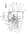
- FIG. 3 illustrates the barring gear assembly according to the invention viewed from above
- FIG. 4 illustrates in perspective the barring gear module according to the invention.
- FIG. 1 illustrates a turbo-alternator group for producing electricity comprising an assembly of steam turbine modules, in this case three turbine modules T 1 , T 2 , T 3 , driving a steam generator 3 .
- This turbo-alternator group rests on a rigid structural frame 5 , generally made of concrete.
- the power produced is between 500 MW and 2000 MW.
- the rotors of the modules of the steam turbine drive the generator 3 in rotation about the axis A.
- the generator is located to the rear of the turbo-alternator group.
- the shaft is extended to the front, at its end opposite the generator 3 , as far as the barring gear assembly 2 .
- the barring gear assembly 2 drives in rotation the shaft 1 via a clutch system 6 which connects or disconnects the shaft 1 to or from the motor 4 .
- the turbine is disconnected from the motor.
- the motor 4 is preferably electric.
- the barring gear assembly can also be placed between two modules of the turbine (T 1 , T 2 , T 3 ) or between the last module of the turbine (here T 3 ) and the generator 3 .
- FIGS. 2 and 3 illustrate more precisely a barring gear assembly 2 .
- a barring gear module 10 is mounted inside a box 7 from which the cover (not illustrated) has been removed to show the inner mechanism. This cover is fixed to the box at the level of the parting line 36 of this box.
- the box 7 has a base 38 extending outside the box, on each side of the shaft.
- the box 7 has two lateral walls 32 , 33 located on either side of the axis of turbine A, a rear wall 34 and a front wall 35 . In operation, the box 7 is closed and sealed, closed by the cover.
- the box has a bearing 8 which receives the rotating end of the shaft 1 .
- the bearing 8 is located against the front wall 35 of the box.
- a main cogged wheel 9 is fixed on the shaft 1 , here at an end. Because of the characteristics of the invention, the wheel 9 can advantageously be fixed on the shaft in a place different to said above end: Preferably, the main wheel 9 could be arranged between two turbine modules or between the last turbine module and the generator. Situated on the peripheral side of said main wheel 9 is the barring gear module 10 . More precisely, the main wheel 9 defines lateral sides C 1 , C 2 located on either side of the axis of rotation A and the barring gear module 10 is positioned on one of the lateral sides, here C 1 , of the axis of rotation A.
- the barring gear module 10 includes the clutch system 6 which comprises a cogged pinion 11 mounted on a secondary shaft 12 .
- the pinion 11 can be moved along said secondary shaft 12 but is connected in rotation to the secondary shaft 12 .
- FIGS. 2 and 3 show the pinion 11 disengaged from the main wheel 9 and the barring gear module 10 is then uncoupled from the shaft 1 .
- Displacement D grips the pinion 11 on the main wheel 9 , the barring gear module 10 then being coupled to the shaft of turbine 1 .
- the dentures of the main wheel 9 and of the pinion 11 are straight dentures for easy engagement of the pinion on the wheel.
- the secondary shaft 12 is mounted to rotate on two upper bearings 13 , 14 located on either side of the pinion 11 .
- the two upper bearings are mounted on the top of a support piece 15 which rests on receiving surfaces of the box 7 .
- the secondary shaft 12 can be set in rotation by a wheel gear reducer 17 and endless screw 18 mounted on the support piece 15 .
- the wheel of the gear reducer 17 is placed to the side of the pinion 11 and between the two upper bearings 13 , 14 of the secondary shaft 12 .
- the endless screw 18 is arranged under the wheel 17 and is located at a level lower than that of the secondary shaft 12 .
- the pinion 11 mounted mobile on the secondary shaft constitutes the clutch system 6 .
- the reduction ratio of the barring gear assembly 2 is decreased relative to that described in relation to the prior art: a motor 4 turning at 750 rpm (1500 rpm previously). Such a motor turning less quickly reduces the overall reduction ratio corresponding to the reduction ratio of the wheel gear reducer 17 and endless screw 18 and the reduction ratio of the wheel 9 and of the pinion 11 .
- the endless screw 18 is extended by a shaft 20 coupled to the motor 4 via the hydraulic coupler and the flexible coupling between the hydraulic coupler and the endless screw.
- the motor is fixed on the bed plate 21 of the box by way of an intermediate piece 37 supporting the motor 4 .
- the endless screw shaft 20 passes through a wall of the box. For this to occur, an opening has been made in the lateral wall 32 . This opening extends from the place of the passage of the shaft 20 as far as the parting line 36 of the box 7 .
- the opening is closed by a removable baffle 22 , here fixed by screws on the lateral wall 32 of the box 7 .
- FIG. 3 shows the compactness of the assembly gained from positioning the clutch system 6 on one side of the main wheel 9 , between the lateral baffle 32 and said main wheel.
- the secondary shaft 12 is arranged on the lateral side of the shaft of turbine 1 and parallel to the latter. Such a compactness can be further increased by having the clutch system 6 at a level lower than that of the shaft 1 .
- FIG. 2 shows the relative position of the secondary shaft 12 relative to the axis of turbine A.
- the secondary shaft 12 is arranged on the lateral side and below the axis of turbine A.
- the barring gear module 10 is preferably arranged at a level lower than that of the parting line of the box 7 .
- the shaft motor 20 is arranged perpendicularly to the shaft of turbine 1 .
- Placing the secondary shaft 12 on the side of the wheel 9 gains length and reduces the length of the shaft 20 and minimises problems due to alignment defaults. Also, placing the secondary shaft 12 below the axis of rotation A gains width.
- Fixing the barring gear module 10 in the box 7 at a level of elevation lower than that of the axis of rotation A of the shaft gives stability to the installation which then dispenses with long non-rigid support feet and likely to vibrate. Also, aligning all the components located on the endless screw shaft 20 (motor 4 , hydraulic coupler 24 , endless screw 18 ) is more stable since the motor is fixed on a more rigid support.
- the endless screw 18 is extended by the shaft 20 which projects outside the box 7 .
- the shaft 20 is located at a level lower than that of the secondary shaft 12 .
- the axis of rotation common to the shaft 20 and to the endless screw 18 is horizontal.
- the end of the shaft 20 is coupled to the motor 4 via a hydraulic coupler 24 and a flexible coupling 25 , both arranged outside the box 7 to minimise oil projections and oil vapour inside the box.
- the flexible coupling 25 tolerates slight alignment default between the motor 4 and the shaft 20 .
- the hydraulic coupler 24 starts up gently with transmitted torque progressively increasing.
- the coupler 24 also attenuates any possible vibrations in rotation. It also protects the motor in the event of blockage of the shaft 1 caused by excess friction.
- the shaft 20 passes through the box via the baffle 22 .
- This baffle is disassemblable by way of screws which aids in installing and removing the barring gear module 10 in the form of the unitary sub-assembly illustrated in FIG. 4 . It is evident that the secondary shaft 12 is on the side of the shaft, with the shaft 20 inside the box 7 being shorter. The consequences of poor alignment are thus reduced.
- the base piece 15 of the barring gear module 10 has on a lower face 27 four support surfaces S 1 , S 2 , S 3 , S 4 which are posed on four receiving surfaces R 1 , R 2 , R 3 , R 4 substantially horizontal in the box 7 .
- Such an arrangement enables easy installation or disassembling of the barring gear module 10 .
- the barring gear module 10 is put in place in the box 7 in the following order:
- the surfaces in contact between the barring gear module and the box could be made in the form of skids, slides or the equivalent to improve precision of displacement of the barring gear module 10 during adjusting.
- the support surfaces 51 , S 2 , S 3 , S 4 are advantageously arranged horizontally to make the barring gear module 10 slide better during adjusting.
- the intermediate piece 15 has the support surfaces S 1 , S 2 , S 3 , S 4 coming into contact with the receiving surfaces R 1 , R 2 , R 3 , R 4 .
- the support surfaces are located near the upper bearings 13 , 14 of the secondary shaft 12 .
- the support piece 15 has a rectangular shape and the support surfaces S 1 , S 2 , S 3 , S 4 are made on a lower face 27 at the four corners of the rectangle.
- the support piece 15 is advantageously made in the form of a plate. Such an arrangement makes both installation and adjustment easier.
- adjustment shims could be intercalated in between the support surfaces 51 , S 2 , S 3 , S 4 of the support plate 15 and the receiving surfaces of the box R 1 , R 2 , R 3 , R 4 . These shims align the dentures of the pinion 11 and of the main wheel 9 by acting on the vertical position of the barring gear module 10 .
- FIG. 4 shows the barring gear module 10 , the wheel 9 being shown only to illustrate the position of the module 10 relative to the axis of rotation A.
- the barring gear module 10 is made in the form of a pre-assembled module made in a single piece.
- the support piece 15 which bears the different constituents is used. It is evident that the support piece is in the form of a plate which bears at both ends the two upper bearings 13 , 14 receiving the secondary shaft 12 in rotation.
- the secondary shaft bears between the bearings 13 , 14 on one side the secondary wheel 17 mounted fixed on this shaft and on the other side the pinion 11 mounted mobile in translation on the secondary shaft 12 .
- the pinion 11 could be shifted by any appropriate device.
- the support piece 15 also receives on a lower face two lower bearings 30 , 31 supporting in rotation the endless screw 18 which is extended by the shaft 20 .
- the endless screw 18 is arranged between the lower bearings 30 , 31 .
Landscapes
- Engineering & Computer Science (AREA)
- Mechanical Engineering (AREA)
- General Engineering & Computer Science (AREA)
- Gear Transmission (AREA)
- Connection Of Motors, Electrical Generators, Mechanical Devices, And The Like (AREA)
Abstract
Description
-
- the presence of the clutch on the shaft makes maintenance operations of the barring gear assembly highly complex. Disassembling the barring gear assembly requires disassembling of the components located between this clutch and the closest end of the shaft. This especially implies long and complex adjustment operations as each component is reassembled. In particular, the presence of the clutch on the shaft disallows positioning of the barring gear assembly between two rotors of the shaft.
- the flexible coupling between the hydraulic coupler and the endless screw placed inside the box are subjected to the atmosphere caused by oil projections and oil vapour. Its shelf life is thus seriously shortened.
- accessibility to the clutch is very difficult,
- the arrangement is not optimal. The presence of the clutch on the shaft necessarily extends said shaft. The general bulk of the turbo-alternator group is thus increased.
-
- first, the barring
gear module 10 is placed above its placement in the box, - the barring
gear module 10 is lowered, during which thescrew shaft 20 descends into the opening of the box, - the piece of
base 15 of the barringgear module 10 is placed on the receiving surfaces R1, R2, R3, R4 of thebox 7, - the barring
gear module 10 is slid towards theshaft 1 and the relative position of the twoshafts pinion 11 andmain wheel 9, - the barring
gear module 10 is fixed on the receiving surfaces R1, R2, R3, R4 of thebox 7 for example by blocking screws, - the
baffle 22 which has an orifice is threaded onto theshaft motor 20, then is fixed on thebox 7, - the
motor 4 is fixed on thebed plate 21 and the motor is coupled to thescrew shaft 20 via thehydraulic coupler 24 and the flexible coupling.
- first, the barring
-
- alignment of the dentures between
pinion 11 andwheel 9 by means of adjustable shims positioned under theplate 15, - alignment of the
motor 4 with the axis of theendless screw 18.
- alignment of the dentures between
Claims (14)
Applications Claiming Priority (3)
| Application Number | Priority Date | Filing Date | Title |
|---|---|---|---|
| FR1059175 | 2010-11-05 | ||
| FR1059175A FR2967208A1 (en) | 2010-11-05 | 2010-11-05 | VIBRATOR ASSEMBLY FOR ROTATING A LINE OF TREE OF A TURBO-ALTERNATOR GROUP. |
| PCT/EP2011/069140 WO2012059471A1 (en) | 2010-11-05 | 2011-10-31 | Barring gear assembly for driving in rotation a shaft of a turbo-alternator group |
Related Parent Applications (1)
| Application Number | Title | Priority Date | Filing Date |
|---|---|---|---|
| PCT/EP2011/069140 Continuation WO2012059471A1 (en) | 2010-11-05 | 2011-10-31 | Barring gear assembly for driving in rotation a shaft of a turbo-alternator group |
Publications (2)
| Publication Number | Publication Date |
|---|---|
| US20130243579A1 US20130243579A1 (en) | 2013-09-19 |
| US9810100B2 true US9810100B2 (en) | 2017-11-07 |
Family
ID=43969401
Family Applications (1)
| Application Number | Title | Priority Date | Filing Date |
|---|---|---|---|
| US13/875,460 Active 2034-03-21 US9810100B2 (en) | 2010-11-05 | 2013-05-02 | Barring gear assembly for driving in rotation a shaft of a turbo-alternator group |
Country Status (6)
| Country | Link |
|---|---|
| US (1) | US9810100B2 (en) |
| EP (1) | EP2635774B1 (en) |
| CN (4) | CN102465724A (en) |
| FR (1) | FR2967208A1 (en) |
| RU (1) | RU112272U1 (en) |
| WO (1) | WO2012059471A1 (en) |
Cited By (1)
| Publication number | Priority date | Publication date | Assignee | Title |
|---|---|---|---|---|
| US11260516B1 (en) | 2020-02-18 | 2022-03-01 | Ryan Roberts | Barring device attachment for providing engine maintenance |
Families Citing this family (12)
| Publication number | Priority date | Publication date | Assignee | Title |
|---|---|---|---|---|
| FR2967208A1 (en) * | 2010-11-05 | 2012-05-11 | Alstom Technology Ltd | VIBRATOR ASSEMBLY FOR ROTATING A LINE OF TREE OF A TURBO-ALTERNATOR GROUP. |
| FR2985285A1 (en) * | 2011-12-29 | 2013-07-05 | Alstom Technology Ltd | DEVICE FOR ACTUATING ROTATION OF A TURBINE SHAFT LINE. |
| ITFI20120194A1 (en) * | 2012-10-01 | 2014-04-02 | Nuovo Pignone Srl | "A TURBINE-DRIVEN RECIPROCATING COMPRESSOR AND METHOD" |
| CN104100311B (en) * | 2014-07-22 | 2015-07-08 | 哈尔滨广瀚新能动力有限公司 | Hydraulic planetary drive type turning gear |
| WO2018124893A1 (en) * | 2016-12-27 | 2018-07-05 | General Electric Company | Adjustable locking block assembly for a toothed gear and methods of using same |
| CN109386322A (en) * | 2018-10-15 | 2019-02-26 | 青岛捷能汽轮机集团股份有限公司 | A kind of automatic barring gear and control method |
| CN109339876B (en) * | 2018-12-10 | 2025-05-16 | 上海风雷阀门集团有限公司 | High speed and high torque radial meshing gear type fully automatic turning device |
| CN110454245A (en) * | 2019-08-30 | 2019-11-15 | 福建福清核电有限公司 | A master cranking device equipped with a quick exhaust valve |
| CN113738459B (en) * | 2020-05-29 | 2024-07-19 | 上海梅山钢铁股份有限公司 | Intelligent jigger control device and control method |
| CN113187566B (en) * | 2021-05-11 | 2022-10-21 | 中国船舶重工集团公司第七0三研究所 | Gear box barring gear |
| CN116007485B (en) * | 2022-12-14 | 2025-09-16 | 国能大渡河检修安装有限公司 | Jigger device |
| CN120868149B (en) * | 2025-09-26 | 2025-12-26 | 湘投国际(衡东)燃气发电有限公司 | Clutch mechanism of low-speed hydraulic power-assisted jigger for power generation gas turbine accident |
Citations (14)
| Publication number | Priority date | Publication date | Assignee | Title |
|---|---|---|---|---|
| DE524329C (en) | 1928-08-31 | 1931-05-13 | Siemens Schuckertwerke Akt Ges | Device for slowly rotating a steam turbine shaft |
| FR1059175A (en) | 1952-06-24 | 1954-03-23 | Papeteries Du Sentier Herve Et | Method of joining together the bands constituting a continuous bundle and bundle thus constituted |
| GB1024895A (en) | 1964-02-13 | 1966-04-06 | Ass Elect Ind | Improved rotor-turning reciprocating mechanism |
| US3485041A (en) * | 1967-12-07 | 1969-12-23 | Westinghouse Electric Corp | Cranking system for a gas turbine |
| US3919894A (en) | 1974-09-30 | 1975-11-18 | Gen Electric | Pre-engagement turning gear |
| DE2422011A1 (en) | 1974-05-07 | 1975-11-20 | Kraftwerk Union Ag | Starting system for turbo generators under load - using a power transmission system operating hydro-dynamically capable of replacing a transmission gear box |
| US4211070A (en) | 1977-06-24 | 1980-07-08 | Bbc Brown Boveri & Company Limited | Start-up motor assembly for rotational machines |
| US4507926A (en) | 1983-05-06 | 1985-04-02 | Aeg-Kanis Turbinenfabrik Gmbh | Rotor rotating device for driving or driven machines |
| US5056989A (en) | 1990-10-01 | 1991-10-15 | Westinghouse Electric Corp. | Stage replacement blade ring flow guide |
| US5088341A (en) * | 1990-02-09 | 1992-02-18 | Westinghouse Electric Corp. | Engaging lever lock for rotor turning gear |
| US7309208B2 (en) * | 2005-02-22 | 2007-12-18 | General Electric Company | Turning gear drive system |
| CN101144510A (en) | 2007-10-18 | 2008-03-19 | 东方电气集团东方汽轮机有限公司 | Automatic synchronous clutch and high-speed cranking device for feedwater pump steam turbine equipped with the clutch |
| CN201588661U (en) | 2009-12-29 | 2010-09-22 | 上海电气电站设备有限公司 | Front mounted approach type variable frequency speed control high-speed turning gear for steam turbine |
| CN202081924U (en) | 2010-11-05 | 2011-12-21 | 阿尔斯通技术有限公司 | Barring component and steamship alternating-current generator set |
-
2010
- 2010-11-05 FR FR1059175A patent/FR2967208A1/en not_active Withdrawn
-
2011
- 2011-03-09 CN CN201110059361XA patent/CN102465724A/en active Pending
- 2011-03-09 CN CN2011200620896U patent/CN202165133U/en not_active Expired - Lifetime
- 2011-04-12 RU RU2011114269/28U patent/RU112272U1/en active
- 2011-04-21 CN CN201110103919.XA patent/CN102465725B/en active Active
- 2011-04-21 CN CN2011201225339U patent/CN202081924U/en not_active Expired - Fee Related
- 2011-10-31 EP EP11776211.2A patent/EP2635774B1/en active Active
- 2011-10-31 WO PCT/EP2011/069140 patent/WO2012059471A1/en not_active Ceased
-
2013
- 2013-05-02 US US13/875,460 patent/US9810100B2/en active Active
Patent Citations (14)
| Publication number | Priority date | Publication date | Assignee | Title |
|---|---|---|---|---|
| DE524329C (en) | 1928-08-31 | 1931-05-13 | Siemens Schuckertwerke Akt Ges | Device for slowly rotating a steam turbine shaft |
| FR1059175A (en) | 1952-06-24 | 1954-03-23 | Papeteries Du Sentier Herve Et | Method of joining together the bands constituting a continuous bundle and bundle thus constituted |
| GB1024895A (en) | 1964-02-13 | 1966-04-06 | Ass Elect Ind | Improved rotor-turning reciprocating mechanism |
| US3485041A (en) * | 1967-12-07 | 1969-12-23 | Westinghouse Electric Corp | Cranking system for a gas turbine |
| DE2422011A1 (en) | 1974-05-07 | 1975-11-20 | Kraftwerk Union Ag | Starting system for turbo generators under load - using a power transmission system operating hydro-dynamically capable of replacing a transmission gear box |
| US3919894A (en) | 1974-09-30 | 1975-11-18 | Gen Electric | Pre-engagement turning gear |
| US4211070A (en) | 1977-06-24 | 1980-07-08 | Bbc Brown Boveri & Company Limited | Start-up motor assembly for rotational machines |
| US4507926A (en) | 1983-05-06 | 1985-04-02 | Aeg-Kanis Turbinenfabrik Gmbh | Rotor rotating device for driving or driven machines |
| US5088341A (en) * | 1990-02-09 | 1992-02-18 | Westinghouse Electric Corp. | Engaging lever lock for rotor turning gear |
| US5056989A (en) | 1990-10-01 | 1991-10-15 | Westinghouse Electric Corp. | Stage replacement blade ring flow guide |
| US7309208B2 (en) * | 2005-02-22 | 2007-12-18 | General Electric Company | Turning gear drive system |
| CN101144510A (en) | 2007-10-18 | 2008-03-19 | 东方电气集团东方汽轮机有限公司 | Automatic synchronous clutch and high-speed cranking device for feedwater pump steam turbine equipped with the clutch |
| CN201588661U (en) | 2009-12-29 | 2010-09-22 | 上海电气电站设备有限公司 | Front mounted approach type variable frequency speed control high-speed turning gear for steam turbine |
| CN202081924U (en) | 2010-11-05 | 2011-12-21 | 阿尔斯通技术有限公司 | Barring component and steamship alternating-current generator set |
Cited By (1)
| Publication number | Priority date | Publication date | Assignee | Title |
|---|---|---|---|---|
| US11260516B1 (en) | 2020-02-18 | 2022-03-01 | Ryan Roberts | Barring device attachment for providing engine maintenance |
Also Published As
| Publication number | Publication date |
|---|---|
| CN202081924U (en) | 2011-12-21 |
| FR2967208A1 (en) | 2012-05-11 |
| EP2635774B1 (en) | 2015-04-22 |
| US20130243579A1 (en) | 2013-09-19 |
| CN202165133U (en) | 2012-03-14 |
| RU112272U1 (en) | 2012-01-10 |
| CN102465724A (en) | 2012-05-23 |
| CN102465725B (en) | 2016-01-20 |
| EP2635774A1 (en) | 2013-09-11 |
| CN102465725A (en) | 2012-05-23 |
| WO2012059471A1 (en) | 2012-05-10 |
Similar Documents
| Publication | Publication Date | Title |
|---|---|---|
| US9810100B2 (en) | Barring gear assembly for driving in rotation a shaft of a turbo-alternator group | |
| EP2713051B1 (en) | A turbine-driven reciprocating compressor and method of operating said compressor | |
| RU2538394C1 (en) | Geared engine for mill drive | |
| US20120039709A1 (en) | Method and device for adjusting the rotor position in a gas turbine or steam turbine | |
| CN107036812A (en) | A kind of electric vehicle gear box testboard bay | |
| RU2556730C2 (en) | Driving device for turbine shafting rotation and turbine-generator set | |
| US10465769B2 (en) | Transmission and transmission turbomachine | |
| US6820472B2 (en) | Test rig and test system for testing a power transmission device | |
| CN102171447A (en) | Method and system for aligning wind turbine components | |
| CN106695672B (en) | Electric-based hydraulic support type aero-engine rotor assembly method and device | |
| EP3428449A1 (en) | Clamping apparatus for positioning a main bearing of a wind turbine during an installation and/or repair procedure | |
| EP2136074A2 (en) | Frame support for a wind turbine nacelle | |
| KR101363051B1 (en) | Turbine case lifting device for powergeneration | |
| CN104599578B (en) | A kind of blower fan centering teaching equipment | |
| US11598406B2 (en) | Phase adjustment system for geared compressor, phase adjustment jig for geared compressor, and method for adjusting phase of geared compressor | |
| KR101363050B1 (en) | Lifting device for turbine inner case | |
| EP4068594A1 (en) | Assembly method and fixing device for electric motor | |
| AU2011310937A1 (en) | Renewable energy generator device and hydraulic pump attachment method | |
| CN114026324A (en) | Improvements relating to generators for wind turbines | |
| CN217637942U (en) | Centering device of wind power complete machine test bed | |
| JP7778488B2 (en) | System and method for retrofitting a power generation system to incorporate clutchless synchronous advance | |
| KR101565074B1 (en) | Vertical hydraulic turbine rotor turning device for checking aberration generator | |
| EP2495438A2 (en) | Turbine drive-train apparatus | |
| CN105119442A (en) | Frame assembly of pull-in coil inserting machine | |
| CN113561128B (en) | Dismounting device and dismounting method for wind power gear box speed ratio wheel |
Legal Events
| Date | Code | Title | Description |
|---|---|---|---|
| AS | Assignment |
Owner name: ALSTOM TECHNOLOGY LTD, SWITZERLAND Free format text: ASSIGNMENT OF ASSIGNORS INTEREST;ASSIGNORS:BASTIER, ARNAUD;MIZERA, JACQUES;SIGNING DATES FROM 20130620 TO 20130823;REEL/FRAME:031119/0452 |
|
| AS | Assignment |
Owner name: GENERAL ELECTRIC TECHNOLOGY GMBH, SWITZERLAND Free format text: CHANGE OF NAME;ASSIGNOR:ALSTOM TECHNOLOGY LTD;REEL/FRAME:039714/0578 Effective date: 20151102 |
|
| STCF | Information on status: patent grant |
Free format text: PATENTED CASE |
|
| MAFP | Maintenance fee payment |
Free format text: PAYMENT OF MAINTENANCE FEE, 4TH YEAR, LARGE ENTITY (ORIGINAL EVENT CODE: M1551); ENTITY STATUS OF PATENT OWNER: LARGE ENTITY Year of fee payment: 4 |
|
| AS | Assignment |
Owner name: POWER SOLUTIONS GAMMA FRANCE, FRANCE Free format text: NUNC PRO TUNC ASSIGNMENT;ASSIGNOR:GENERAL ELECTRIC TECHNOLOGY GMBH;REEL/FRAME:069450/0966 Effective date: 20241122 Owner name: ARABELLE TECHNOLOGIES, FRANCE Free format text: CHANGE OF NAME;ASSIGNOR:POWER SOLUTIONS GAMMA FRANCE;REEL/FRAME:069451/0916 Effective date: 20240531 |
|
| AS | Assignment |
Owner name: ARABELLE SOLUTIONS FRANCE, FRANCE Free format text: MERGER;ASSIGNOR:ARABELLE TECHNOLOGIES;REEL/FRAME:070587/0348 Effective date: 20241203 |
|
| MAFP | Maintenance fee payment |
Free format text: PAYMENT OF MAINTENANCE FEE, 8TH YEAR, LARGE ENTITY (ORIGINAL EVENT CODE: M1552); ENTITY STATUS OF PATENT OWNER: LARGE ENTITY Year of fee payment: 8 |