US9806800B2 - Optical Ethernet apparatus capable of reset control - Google Patents
Optical Ethernet apparatus capable of reset control Download PDFInfo
- Publication number
- US9806800B2 US9806800B2 US15/003,972 US201615003972A US9806800B2 US 9806800 B2 US9806800 B2 US 9806800B2 US 201615003972 A US201615003972 A US 201615003972A US 9806800 B2 US9806800 B2 US 9806800B2
- Authority
- US
- United States
- Prior art keywords
- command
- optical
- recovery
- pattern
- output
- Prior art date
- Legal status (The legal status is an assumption and is not a legal conclusion. Google has not performed a legal analysis and makes no representation as to the accuracy of the status listed.)
- Active, expires
Links
- 230000003287 optical effect Effects 0.000 title claims abstract description 157
- 238000011084 recovery Methods 0.000 claims abstract description 187
- 230000005540 biological transmission Effects 0.000 claims abstract description 25
- 238000000034 method Methods 0.000 claims abstract description 13
- 230000004044 response Effects 0.000 claims description 23
- 238000001514 detection method Methods 0.000 claims description 18
- 238000006243 chemical reaction Methods 0.000 claims description 11
- 238000010586 diagram Methods 0.000 description 16
- 238000005516 engineering process Methods 0.000 description 7
- 230000008859 change Effects 0.000 description 3
- 238000012986 modification Methods 0.000 description 3
- 230000004048 modification Effects 0.000 description 3
- 230000008672 reprogramming Effects 0.000 description 3
- 239000000835 fiber Substances 0.000 description 2
- 230000007704 transition Effects 0.000 description 2
- 230000004913 activation Effects 0.000 description 1
- 238000010276 construction Methods 0.000 description 1
- 239000000284 extract Substances 0.000 description 1
- 238000009434 installation Methods 0.000 description 1
- 238000004519 manufacturing process Methods 0.000 description 1
- 238000012544 monitoring process Methods 0.000 description 1
- 230000003252 repetitive effect Effects 0.000 description 1
- 239000004065 semiconductor Substances 0.000 description 1
Images


Classifications
-
- H—ELECTRICITY
- H04—ELECTRIC COMMUNICATION TECHNIQUE
- H04B—TRANSMISSION
- H04B10/00—Transmission systems employing electromagnetic waves other than radio-waves, e.g. infrared, visible or ultraviolet light, or employing corpuscular radiation, e.g. quantum communication
- H04B10/03—Arrangements for fault recovery
-
- H—ELECTRICITY
- H04—ELECTRIC COMMUNICATION TECHNIQUE
- H04L—TRANSMISSION OF DIGITAL INFORMATION, e.g. TELEGRAPHIC COMMUNICATION
- H04L41/00—Arrangements for maintenance, administration or management of data switching networks, e.g. of packet switching networks
- H04L41/06—Management of faults, events, alarms or notifications
- H04L41/0654—Management of faults, events, alarms or notifications using network fault recovery
- H04L41/0659—Management of faults, events, alarms or notifications using network fault recovery by isolating or reconfiguring faulty entities
- H04L41/0661—Management of faults, events, alarms or notifications using network fault recovery by isolating or reconfiguring faulty entities by reconfiguring faulty entities
-
- H04L41/0672—
Definitions
- the following description relates to an Ethernet-based optical transmission system, and more particularly, to an apparatus and method for controlling remote optical Ethernet equipment.
- Optical Ethernet equipment has been increasingly installed for fiber to the curb (FTTC) services and fiber to the home (FTTH) services, while the installation locations thereof are expanding beyond telephone stations to unmanned remote stations, apartments' terminal boxes, utility poles, and manholes.
- FTTC fiber to the curb
- FTTH fiber to the home
- Korean Patent Application Publication No. 10-2006-36334 discloses a central station apparatus that can initialize remote Ethernet equipment using a physical layer of said equipment. More specifically, a laser driver LD that constitutes an optical module at a central office side is provided with an LD enable pin, and the LD enable pin is controlled to transmit a predetermined on/off repeating signal to a remote optical Ethernet switch, thereby reinitiating a relevant optical Ethernet switch.
- the following description relates to a technology that can reduce repetitive resetting of a system due to instability of an optical Ethernet apparatus.
- the technology is aim to provide a remote reset function, with minimum changes in an existing system. Further, the technology provided herein is to enable an existing system to add said remote reset function thereto by remote update.
- an optical Ethernet apparatus comprising: an optical receiver configured to perform photoelectric conversion on packet data received through an optical transmission medium; an optical transmitter configured to perform electrophotic conversion for an output to an optical transmission medium; a signal detector configured to detect whether the optical receiver receives an effective optical signal and output a resulting detection signal; a system recovery controller configured to detect, as a system recovery command, an output from the signal detector that includes a predetermined pattern which is repeated a designated number of times for a designated period of time, and to output a system recovery control command; and a system recovery processor configured to output a system reset signal or a system power ON/OFF control signal in response to the system recovery control command.
- a counter may be reset in response to a signal pattern which is detected by the pattern detector and does not occur during the determined period of time.
- a threshold recovery value and a reference time value may be remotely set to specific values.
- the pattern detector may be implemented as a first programmable logic device, and the command recognizer may be implemented as a second programmable logic device connected to a system controller.
- the first programmable logic device may be located in a first circuit module that includes the optical receiver and the optical transmitter.
- the second programmable logic device may be located in a second circuit module that includes the power supply and the system controller.
- the system controller may control the power supply, and may further include a remote programming part that stores program codes for programming the second circuit module.
- an optical Ethernet apparatus including: a plurality of optical transmitters; a plurality of optical receivers; a plurality of signal detectors; a plurality of pattern detectors; a plurality of command recognizers, each of which is provided to each of the plurality of pattern detectors; and a logic detector configured to output a system recovery control command in response to a system recovery command being detected from one of the plurality of command recognizers.
- the optical Ethernet apparatus may further include: a remote recovery command generator configured to output a remote system recovery command that occurs when a predetermined signal pattern is repeated a designated number of times for a designated period of time; and a remote recovery part configured to control ON/OFF of transmission power of the optical transmitter in response to the remote system recovery command output from the remote recovery command generator.
- a remote recovery command generator configured to output a remote system recovery command that occurs when a predetermined signal pattern is repeated a designated number of times for a designated period of time
- a remote recovery part configured to control ON/OFF of transmission power of the optical transmitter in response to the remote system recovery command output from the remote recovery command generator.
- a recovery method for an optical Ethernet apparatus including: detecting a predetermined signal pattern of a system recovery command; detecting a system recovery command that occurs when a predetermined signal pattern is repeated a designated number of times for a designated period of time, and, in turn, outputting a system recovery control command; and outputting a system reset signal or a system power ON/OFF control signal in response to the system recovery control command.
- the outputting of the system recovery control command may include counting a number of times the predetermined signal pattern is detected, and checking a time at which the predetermined signal pattern is detected.
- the outputting of the system recovery control command may include restarting counting is in response to the detected signal pattern which does not occur during the designated period of time.
- FIG. 1 is a block diagram illustrating an optical Ethernet apparatus according to an exemplary embodiment.
- FIGS. 2A to 2C are block diagram illustrating a system recovery controller of the optical Ethernet apparatus.
- FIG. 3 is a block diagram illustrating a first circuit module and a second circuit module of an optical Ethernet apparatus according to another exemplary embodiment.
- FIG. 4 is a block diagram illustrating in detail the optical Ethernet apparatus of FIG. 3 .
- FIG. 5 is a block diagram illustrating an optical Ethernet apparatus that receives optical signals from multiple transmission media according to another exemplary embodiment.
- FIG. 6 is a block diagram illustrating an optical Ethernet apparatus capable of remotely recovering a system of another optical Ethernet apparatus.
- FIG. 7 is a flowchart illustrating a recovery method for recovering a system of an optical Ethernet apparatus according to an exemplary embodiment.
- FIG. 8 is a state transition diagram of a control flow of an optical Ethernet apparatus applicable to the above exemplary embodiments shown in FIGS. 1 to 7 .
- An optical Ethernet apparatus described herein may be one of an Ethernet switch equipped with optical ports, a VDSL concentrator, a wireless connector, a PON device, Home Gateway, and an Ethernet-based set-top box.
- FIG. 1 is a block diagram illustrating an optical Ethernet apparatus according to an exemplary embodiment.
- the optical Ethernet apparatus includes an optical receiver 10 , an optical transmitter 20 , a signal detector 30 , a system recovery controller, and a system recovery processor.
- the optical receiver 10 performs photoelectric conversion on packet data input through a transmission medium.
- the optical receiver 20 performs electrophotic conversion for an output to an optical transmission medium.
- the signal detector 30 detects whether the optical receiver 10 receives an effective optical signal, and then the detector 30 outputs a resulting signal.
- the effective optical signal refers to an optical signal having a power with an effective range. If it is detected that no signal is generated from the photoelectric conversion or a weak signal is received, the signal detector 30 outputs a negative logic level signal.
- the system recovery controller 40 detects the output as a system recovery command, and then outputs a system recovery control command.
- the predetermined signal pattern is a signal output pattern in which a signal detect/loss of signal (SD/LOS) signal is alternated a specific number of times.
- SD/LOS signal detect/loss of signal
- the system recovery control command is to reset a system or turn on or off a system power.
- a duration of time and the number of time for which the predetermined signal pattern has to be repeated may be predetermined. Therefore, the system recovery controller 40 may monitor outputs from the signal detector 30 and detect an output that satisfies the requirements. Only when an output that satisfies the requirements is detected, the system recovery controller 40 outputs the system recovery control command.
- the system recovery controller 40 may be implemented as a program. When the number of times that the predetermined signal pattern is detected within a threshold time designated by counting the time of loop reaches a threshold value, the system recovery controller 40 outputs the recovery control command. Another exemplary embodiment will be described later.
- the system recovery processor 50 outputs a system reset signal or a system power ON/OFF control signal according to the system recovery control command.
- the system recovery controller 40 may detect a system recovery command which resets a system or turns on or off the system power according to a type of predetermined signal pattern.
- the system recovery controller 40 may detect a system recovery command which resets the system or turns on or off the system power according to a predesignated time or the predesignated number of times.
- the system recovery processor 50 may output a signal to control the system to be reset or to turn on or off the power according to the system recovery control command.
- FIG. 2A is a block diagram illustrating the system recovery controller according to another exemplary embodiment.
- the system recovery controller 40 may include a pattern detector 41 and a command recognizer 42 .
- the pattern detector 41 and the command recognizer 42 are implemented as individual programmable logics.
- the pattern detector 41 detects a predetermined signal pattern output from the pattern signal detector 30 , and outputs a pattern detection signal.
- the pattern detector 41 is detection logic for a system recovery control command according to a related art.
- the pattern detector 41 is not directly connected to a central processing unit (CPU) that controls the system, and hence it is not possible to remotely upgrade or re-program the pattern detector 41 .
- the signal detector 30 detects an effective optical signal among optical signals received from the optical receiver 10 , and outputs the effective optical signal to the pattern detector 41 , the pattern detector 41 continuously monitors the output signals.
- the pattern detector 41 When detecting the predetermined signal pattern during monitoring the output signals, the pattern detector 41 outputs a pattern detection signal to the command recognizer 42 to indicate the detection of predetermined signal pattern.
- the predetermined signal pattern may be, for example, square wave that is periodically repeated five times.
- the predetermined signal pattern may result from periodically turning on or off the output power of the optical transmitter 20 .
- the pattern detector 41 may output one pulse when detecting the arranged pattern.
- the command recognizer 42 counts the pattern detection signals and determines whether the predetermined signal pattern is repeated the designated number of times for a designated period of time.
- the command recognizer 42 includes a counter 43 , a recovery command detector 45 , and a timer 46 .
- the counter 43 and the timer 46 each may be implemented as an independent circuit.
- the counter 43 counts the number of pattern detection signals output from the pattern detector 41 and outputs the count.
- the pattern detector 41 outputs a pattern detection signal each time the predetermined signal pattern is detected, and the counter 43 counts the number of pattern detection signals output from the pattern detector 41 .
- the counter 43 cumulatively counts the number of pattern detection signals output.
- the timer 46 may operate in one of plurality of modes that include an operation mode and a counter mode, wherein in the operation mode, an output line is switched to an activation state to indicate that a set period of time has elapsed, and in the counter mode, the timer 46 counts the time elapsed since reset and then outputs the count.
- the timer may refer to the former, but the present disclosure does not rule out the counter mode or modifications of the counter mode.
- the timer 46 is reset when the first signal pattern is detected and, in turn, the pattern detector 41 outputs a pulse.
- the recovery command detector 45 reads the count output from the counter 43 and a value of the timer 46 , and outputs a system recovery control command according to the read count and value. For example, the recovery command detector 45 outputs a system recovery control command when the count value of the counter reaches a threshold value, for example, 3, during a threshold time period, for example, 50 seconds, since the first signal pattern was received. If the count exceeds 3 (e.g., 5) or the count does not reach 3 (e.g., 2) during the 50 seconds, the recovery command detector 45 does not output the system recovery control command.
- a threshold value for example, 3, during a threshold time period, for example, 50 seconds
- the command recognizer 42 may reset the counter if the signal pattern detected by the pattern detector 41 was not generated during the designated period of time.
- FIG. 2B is a block diagram illustrating the system recovery controller according to another exemplary embodiment.
- a command recognizer 42 includes a counter 43 , a recovery command detector 45 , a first timer 46 - 1 , and a second timer 46 - 2 .
- the first timer 46 - 1 and the second timer 46 - 2 may be implemented as independent timers provided in one timer chip 46 , and may form two channels on the single timer chip.
- the first timer 46 - 1 is reset when the command recognizer 42 waits for the first input of a pattern detection signal in order to determine whether a new system recovery control command is to be generated, and then the first timer 46 - 1 starts counting.
- the second timer 46 is reset each time the pattern detector 41 detects a signal pattern.
- the first timer 46 - 1 may be set to 50 seconds and the second timer 46 - 2 may be set to 20 seconds.
- command detector 45 - 1 and the timing checker 45 - 2 to detect changes in the count value of counter 43
- various methods may be used, such as polling by which the value of counter 43 is periodically read, or interrupting a microprocessor or logic when a value of counter 43 changes, wherein the recovery command detector 45 implemented in the microprocessor or logic.
- the timing checker 45 - 2 detects the change in counter value and checks a state of the second timer 46 - 2 . If the second timer 46 - 2 is still running, then it indicates that the third signal pattern arrives too early, and thus the timing checker 45 - 2 resets the counter 43 . If the second timer 46 - 2 has ended, the command detector 45 - 1 checks the first timer 46 - 1 . If the first timer 46 - 1 has ended, it indicates that the predesignated threshold time has already elapsed, so the command detector 45 - 1 does not generate a system recovery control command, but returns to the initial state. If the first timer 46 - 1 has not ended, it indicates that three signal patterns have arrived within the predesignated threshold period of time, and thus the command detector 45 - 1 generates and outputs a system recovery control command.
- the first timer 46 - 1 is set to 50 seconds and the second timer 46 - 2 is set to 20 seconds
- predetermined signal patterns arrive at 0 second, 25 seconds, and 40 seconds, respectively, it means that the third signal pattern arrives 15 seconds after the second signal pattern, and hence a system recovery control command is not generated and the counter 43 is reset immediately after the third signal pattern has arrived.
- predetermined signal patterns arrive at 10 second, 23 seconds, and 49 seconds, respectively, it indicates that three signal patterns have arrived within 50 seconds at appropriate intervals, and hence a system recovery control command is output.
- FIG. 2C is a block diagram illustrating the system recovery controller according to yet another exemplary embodiment.
- the example shown in FIG. 2C is similar to the system recovery controller of FIG. 2A , except that the system recovery controller of FIG. 2C further includes a counter register 80 , a timer register 81 , and a remote setup part 47 .
- the remote setup part 47 is implemented as a program on a CPU that constitutes a system controller.
- the remote setup part 47 may receive data from an external source and record setting values extracted from said data in the counter register 80 and the timer register 81 .
- the counter register 80 stores a threshold recovery value that is a reference, i.e., a setting value, of the counter 43 .
- the timer register 81 stores a threshold time, i.e., a reference time value, of one or more timers that are included in the timer 46 .
- the threshold time value may be a single constant for one timer, or two constants that specify a threshold range for two timers.
- FIG. 3 is a block diagram illustrating an optical Ethernet apparatus according to another exemplary embodiment. Elements similar to those in FIGS. 1, 2A, 2B, and 2C are denoted by the same reference numerals.
- a power supply 51 provides power to the system.
- the entire system may be reset or turned on or off by powering on or off the power supply 51 .
- the system may be reset by resetting the system controller 60 or assigning an interrupt to the system controller 60 to execute a reset routine that resets the entire system.
- the command recognizer 42 may output a system recovery control command to power on or off the power supply 51 .
- the optical Ethernet apparatus consists of a first circuit module 100 and a second circuit module 200 .
- the first circuit module 100 includes an optical receiver 10 , an optical transmitter 20 , a signal detector 30 , and a pattern detector 41 .
- the second circuit module 200 includes a command recognizer 42 , a power supply 51 , and a system controller 60 .
- the first circuit module 100 may further include a remote recovery part 70 .
- the signal detector 30 is integrated into a part of the optical receiver 10 .
- the remote recovery part 70 is a switch to turn on/off transmission power of the optical transmitter 20 and is integrated into a part of the optical transmitter 20 .
- the portion surrounded by a dotted line is provided as a commercialized optical connector part called an “optical transceiver.”
- the pattern detector 41 is one programmable logic device mounted on a circuit board to which the optical connector part is mounted, and the first circuit module 100 is a technology applied to a conventional optical Ethernet apparatus.
- the pattern detector 41 and the command recognizer 42 are implemented as separate programmable logic devices.
- One programmable logic device for the pattern detector 41 is set to detect a predetermined signal pattern. Since said programmable logic device is not connected to the system controller 60 that controls the entire system, the programmable logic device, which has been initially programmed to detect a specific predetermined signal pattern in a manufacturing process, cannot be updated or re-programmed to detect another signal pattern.
- the system controller 60 when the optical Ethernet apparatus receives an optical signal through the optical receiver 10 and detects a system recovery control command, the system controller 60 builds criteria for the command recognizer 42 to recognize a detected signal as a system recovery control command.
- the system controller 60 may specify the specific number of times and a threshold period of time for detecting a predetermined signal pattern, wherein the predetermined signal patterns constitute a system recovery control command.
- the system controller 60 may change criteria for the command recognizer 42 implemented as another programmable logic device, regarding the number of times and a period of time for detecting a predetermined signal pattern.
- the system controller 60 may program said programmable logic device, which is the command recognizer 42 , by controlling the power supply 51 .
- Said programmable logic device may be reconfigured to have new features by being reprogrammed through the system controller 60 and the power supply 51 .
- the system controller 60 may control the power supply 51 to provide the programmable logic device that forms the command recognizer 42 with power needed for programming, and then sequentially output programming codes, which have been received from an external source, according to the programming sequence, thereby reprogramming said reprogrammable logic device. It is possible to configure the command recognizer 42 proposed herein by reprogramming an existing programmable logic device that is originally provided for a different function for the conventional technology.
- the system controller 60 may control an optical signal output from the optical transmitter 20 in order for the optical Ethernet apparatus to remotely recover the system.
- the optical Ethernet apparatus may further include the remote recovery part 70 that controls ON/OFF of the transmission power of the optical transmitter 20 in response to a remote system recovery command which occurs when a predetermined signal pattern is repeated a predesignated number of times for a predesignated length of time.
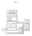
- FIG. 4 is a block diagram illustrating in detail the optical Ethernet apparatus of FIG. 3 .
- the command recognizer 42 includes the recovery command detector 45 , the counter 43 , and the timer 46 .
- the exemplary embodiments of the command recognizer 42 are already described as above with reference to FIGS. 2A to 2C .
- the command recognizer 42 may include the counter register 80 and the timer register 81 , which are already described above.
- the system controller 60 may further include a remote recovery command generator 61 that outputs a remote system recovery command which occurs when a predetermined signal pattern occurs repetitively a predesignated number of times for a predesignated period of time.
- the remote recovery command generator 61 outputs a pulse waveform to the remote recovery part 70 such that a signal pattern occurs repetitively a predesignated number of times for a predesignated period of time.
- the remote recovery command generator 61 is implemented by program codes in the CPU that constitutes the system controller 60 , but the present disclosure is not limited to thereto, such that the remote recovery command generator 61 may be implemented by a variety of known programmable logic devices or dedicated circuitry.
- the remote recovery command generator 61 outputs a remote system recovery control command which occurs when a predetermined signal pattern occurs repetitively a predesignated number of times for a predesignated period of time.
- the remote recovery command generator 61 outputs a remote system recovery control command according to requirements regarding repetition for the predetermined signal pattern to be recognized as a system recovery control command by another optical Ethernet apparatus.
- the predetermined signal pattern is a pattern of a SD/LOS signal that is output repetitively a certain number of times.
- the remote recovery part 70 is configured to include a semiconductor switch that turns on/off the transmission power of the optical transmitter 20 .
- the remote recovery part 70 controls ON/OFF of the transmission power of the optical transmitter 20 in response to the remote system recovery control command output from the remote recovery command generator 61 .
- the remote discovery part 70 controls the predetermined signal pattern to occur a certain number of times for a certain period of time such that the optical Ethernet apparatus that receives said signal pattern can recognize the system recovery command and, in turn, recovers a system.
- the system controller 60 may further include a remote setup part 62 to set the counter register 80 and the timer register 81 according to data value received from an external source.
- the remote setup part 62 extracts data by parsing, for example, data packets received through a network, determines a counter register value and a timer register value among the extracted data, and records the two register values.
- the remote setup part 62 is implemented by program codes in the CPU that constitutes the system controller 60 , but the present disclosure is not limited to thereto, such that the remote setup part 62 may be implemented by a variety of known programmable logic devices or dedicated circuitry.
- the system controller 60 may further include a remote programming part 63 that includes program codes for programing a second circuit module by controlling the power supply.
- the remote programming part 63 downloads a program through a network to program a programmable logic device. Then, the remote programming part 63 controls the power supply 51 to increases the power of electric signals, which are output from the system controller 60 to the command recognizer 42 , to a level suitable for programing the programmable logic device. It is possible to configure the command recognizer 42 proposed herein by reprogramming an existing programmable logic device that is originally provided for a different function for the conventional technology.
- the remote programming part 63 is implemented by program codes in the CPU that constitutes the system controller 60 , but the present disclosure is not limited thereto, such that the remote programming part 63 may be implemented by a variety of known programmable logic devices or dedicated circuitry.
- the optical Ethernet device may include multiple optical transmitters, multiple optical receivers, multiple signal detectors, multiple pattern detectors, a plurality of command recognizer provided respectively to the multiple pattern detectors, and a logic detector that outputs a system recovery control command when any one of the command recognizers detects a system recovery command.
- FIG. 5 is a block diagram illustrating the optical Ethernet apparatus according to yet another exemplary embodiment.
- the optical Ethernet apparatus may include two optical transmitters 20 - 1 and 20 - 1 , two optical receivers 10 - 1 and 10 - 2 , two signal detectors 30 - 1 and 30 - 2 , and two pattern detectors 40 - 1 and 40 - 2 .
- the number of each element described above is not limited to 2, and it may vary.
- each of the pattern detectors 40 - 1 and 40 - 2 provided to each of the optical receivers 10 - 1 and 10 - 2 detects a predetermined signal pattern.
- Each of the command recognizers 42 - 1 and 42 - 2 provided to each of the pattern detector 40 - 1 and 40 - 2 determines whether the predetermined signal pattern is a system recovery command.
- the optical Ethernet apparatus includes the logic detector 90 that outputs a system recovery control command when one of the command recognizers 42 - 1 and 42 - 2 detects a system recovery command.
- the logic detector 90 outputs a system reset signal or a system power ON/OFF control signal when one of the command recognizers 42 - 1 and 42 - 2 detects a system recovery command.
- the logic detector 90 is an OR gate, outputting a system recovery control command in response to a system recovery command detected by one of the command recognizers 42 - 1 and 42 - 2 .
- the pattern detectors 40 - 1 and 40 - 2 are implemented as one programmable logic device, and the command recognizers 42 - 1 and 42 - 2 and the logic detector 90 are implemented as another programmable logic device connected to a system controller.
- the remote recovery command generator 61 is also implemented in the same programmable logic device as the command recognizers 42 - 1 and 42 - 2 and the logic detector 90 .
- the remote recovery command generator 61 When the system controller 60 instructs the transmission of a remote recovery control command, the remote recovery command generator 61 generates a remote recovery command with reference to the internal counter register and timer register and outputs said command to one of a plurality of optical connector modules, i.e., a designated port, wherein the remote recovery command occurs when a predetermined signal pattern is repeated a threshold number of times for a threshold period of time.
- the programmable logic device in which the pattern detectors are implemented is located in a first circuit module that includes the optical receiver and the optical transmitter
- the other programmable logic device in which the command recognizers 42 - 1 and 42 - 2 , the logic detector 90 and the remote recovery command generator 61 are implemented is located in a second circuit module that includes the power supply 51 and the system controller 60 . Since the plurality of command recognizers 42 - 1 and 42 - 2 , the logic detector 90 , and the remote recovery command generator 61 are all implemented as one programmable logic device, actual electronic parts of the present exemplary embodiment are similar to those of the exemplary embodiment shown in FIG. 4 , except that a plurality of first circuit modules are provided, which are optical connector modules. In the present exemplary, remote setting and/or remote programming are also possible, as shown in FIG. 4 .
- FIG. 6 is a block diagram illustrating an optical Ethernet apparatus capable of remotely recovering a system of another optical Ethernet apparatus.
- the optical Ethernet apparatus includes an optical receiver 10 to perform photoelectric conversion on packet data input through an optical transmission medium, an optical transmitter 20 to perform electrophotic conversion for an output to the optical transmission medium, and a physical layer part 300 which is an OSI physical layer for encoding and decoding transmission and reception data and data serialization/deserialization.
- the optical Ethernet apparatus may include a remote recovery command generator 61 , a recovery command generator 61 , and a remote recovery part 70 .
- the remote recovery command generator 61 outputs a remote system recovery command that occurs when a predetermined signal pattern is repeated a predetermined number of times for a predetermined period of time.
- the remote recovery part 70 controls ON/OFF of transmission power of the optical transmitter 20 in response to a remote system recovery command output from the recovery command generator 61 .
- the optical Ethernet apparatus is able to remotely control another optical Ethernet apparatus by the use of the remote recovery command generator 61 and the remote recovery command generator 70 .
- the remote recovery command generator 61 outputs a remote system recovery control command that occurs when a predetermined signal pattern is repeated a predesignated number of times for a predesignated period of time. In one exemplary embodiment, the remote recovery command generator 61 outputs a remote system recovery control command according to requirements regarding repetition for the predetermined signal pattern to be recognized as a system recovery command by another optical Ethernet apparatus.
- the remote recovery part 70 controls ON/OFF of transmission power of the optical transmitter 20 in response to a remote system recovery control command output from the remote recovery command generator 61 .
- the remote recovery part 70 controls the predetermined signal pattern to be output by controlling ON/OFF of the transmission power of the optical transmitter 20 .
- the remote recovery part 70 controls the predetermined signal pattern to occur a specific number of times for a specific period of time, so that the optical Ethernet apparatus that receives said signal pattern can recognizes said signal pattern as the system recovery command and, in turn, recovers a system.
- the remote recovery command generator 61 may be implemented as a programmable logic device or a program in a CPU that constitutes the system controller.
- FIG. 7 is a flowchart illustrating a recovery method for recovering a system of an optical Ethernet apparatus according to an exemplary embodiment.
- the recovery method includes detection of a predetermined signal pattern of a system recovery command, as depicted in S 1 .
- the predetermined signal pattern may be an output pattern of an SD/LOS signal.
- N p and t p are set in advance, and can be re-set, as needed.
- an operation of outputting the system recovery control command includes operation S 2 in which the number of times the predetermined signal pattern is detected is counted and operation S 3 in which the time at which the predetermined signal pattern is detected is checked.
- the number of times a predetermined signal pattern is detected is counted and it is checked whether the N-th signal pattern occurs during a designated period of time (from t n to t n+1 .
- a threshold time period (from t 2 to t 3 ) during which the second signal pattern is to be detected and a threshold time period (from t 3 to t 4 ) during which the third signal pattern is to be detected may be set to be different from each other. If the N-th signal pattern occurs during the designated period of time, the number of times the predetermined signal pattern is detected continues to be counted and it is checked whether the count of said number of times reaches a threshold value N p until a threshold time t p .
- the operation of outputting the system recovery control command may further include an operation of restarting the count of the detected predetermined signals if the detected signal pattern does not occur during a designated period of time.
- the N-th signal pattern does not occur during a designated period of time (from t n to t n+1 )
- the counter 43 and the timer 46 are reset.
- the counter 43 and the timer 46 are both reset.
- FIG. 8 is a state transition diagram of a control flow of an optical Ethernet apparatus applicable to the above exemplary embodiments.
- a counter and timers are reset. If a signal pattern is detected during a standby state, the state is switched to state S 1 and then the counter is increased by 1. Then, if a checked counter value is smaller than a threshold recovery value N p , the state is switched to state S 2 .
- the apparatus waits for another signal pattern, and when receiving the signal pattern, checks the timer. If the apparatus receives the signal pattern when the timer value falls within a reference range of values, the state is switched to state S 1 .
- the state is switched to state S 0 , at which the timers and the counter are all initialized. If the counter value reaches a threshold recovery value Np as state S 1 and state S 2 are repeatedly switched, the counter value is checked at state S 1 . If the checked counter value is equal to or greater than the threshold recovery value N p , the state is switched to S 3 and the system power is rebooted after a specific period of time, for example, 3 seconds.
- a system of an optical Ethernet apparatus is recovered remotely, and a control signal for generating a system recovery command may be configured to include particular pattern and particular requirements regarding repetition of said pattern.
- a control signal for generating a system recovery command may be configured to include particular pattern and particular requirements regarding repetition of said pattern.
- the control signal it is possible to generate a system recovery command only when the particular pattern occurs at accurate timing, so that it is prevented that an undesired system recovery command is generated due to unstable factors on a line.
Landscapes
- Engineering & Computer Science (AREA)
- Computer Networks & Wireless Communication (AREA)
- Signal Processing (AREA)
- Physics & Mathematics (AREA)
- Electromagnetism (AREA)
- Small-Scale Networks (AREA)
Abstract
Description
Claims (20)
Applications Claiming Priority (2)
| Application Number | Priority Date | Filing Date | Title |
|---|---|---|---|
| KR10-2016-0000601 | 2016-01-04 | ||
| KR1020160000601 | 2016-01-04 |
Publications (2)
| Publication Number | Publication Date |
|---|---|
| US20170195042A1 US20170195042A1 (en) | 2017-07-06 |
| US9806800B2 true US9806800B2 (en) | 2017-10-31 |
Family
ID=59235931
Family Applications (1)
| Application Number | Title | Priority Date | Filing Date |
|---|---|---|---|
| US15/003,972 Active 2036-06-02 US9806800B2 (en) | 2016-01-04 | 2016-01-22 | Optical Ethernet apparatus capable of reset control |
Country Status (1)
| Country | Link |
|---|---|
| US (1) | US9806800B2 (en) |
Families Citing this family (4)
| Publication number | Priority date | Publication date | Assignee | Title |
|---|---|---|---|---|
| US10298293B2 (en) | 2017-03-13 | 2019-05-21 | At&T Intellectual Property I, L.P. | Apparatus of communication utilizing wireless network devices |
| US10936399B2 (en) * | 2018-11-30 | 2021-03-02 | Foxconn Interconnect Technology Limited | System and method for performing automatic recovery after a system hard fault has occurred in a controller of an optical communications module |
| CN109857000B (en) * | 2018-12-20 | 2021-01-26 | 奥克斯空调股份有限公司 | Automatic startup control method and device and remote controller |
| CN118981197B (en) * | 2024-07-31 | 2025-10-31 | 奇瑞汽车股份有限公司 | CANoe-based method and system for recovering strategy after test bus closing |
Citations (7)
| Publication number | Priority date | Publication date | Assignee | Title |
|---|---|---|---|---|
| US6307652B1 (en) * | 1998-04-28 | 2001-10-23 | Weed Instrument Company, Incorporated | Fault tolerant optical communication apparatus and method |
| US6480946B1 (en) * | 1998-11-09 | 2002-11-12 | Mitsubishi Denki Kabushiki Kaisha | Memory system for synchronized and high speed data transfer |
| KR20030046663A (en) | 2001-12-06 | 2003-06-18 | 삼성전자주식회사 | Apparatus and method for remote reset bts |
| KR20040035057A (en) | 2002-10-18 | 2004-04-29 | 주식회사 에치에프알 | Method and Apparatus for Measuring an Inter-Repeater Delay Time in Mobile Communication System |
| KR20060036334A (en) | 2004-10-25 | 2006-04-28 | 노베라옵틱스코리아 주식회사 | Optical Ethernet device with operational management of the physical layer |
| KR101160448B1 (en) | 2010-11-10 | 2012-06-27 | (주)유비쿼스 | Apparatus and method for remote power control based on ethernet or PONpassive optical network |
| US20140112661A1 (en) * | 2012-10-19 | 2014-04-24 | Fujitsu Telecom Networks Limited | Optical transmission device and method |
-
2016
- 2016-01-22 US US15/003,972 patent/US9806800B2/en active Active
Patent Citations (7)
| Publication number | Priority date | Publication date | Assignee | Title |
|---|---|---|---|---|
| US6307652B1 (en) * | 1998-04-28 | 2001-10-23 | Weed Instrument Company, Incorporated | Fault tolerant optical communication apparatus and method |
| US6480946B1 (en) * | 1998-11-09 | 2002-11-12 | Mitsubishi Denki Kabushiki Kaisha | Memory system for synchronized and high speed data transfer |
| KR20030046663A (en) | 2001-12-06 | 2003-06-18 | 삼성전자주식회사 | Apparatus and method for remote reset bts |
| KR20040035057A (en) | 2002-10-18 | 2004-04-29 | 주식회사 에치에프알 | Method and Apparatus for Measuring an Inter-Repeater Delay Time in Mobile Communication System |
| KR20060036334A (en) | 2004-10-25 | 2006-04-28 | 노베라옵틱스코리아 주식회사 | Optical Ethernet device with operational management of the physical layer |
| KR101160448B1 (en) | 2010-11-10 | 2012-06-27 | (주)유비쿼스 | Apparatus and method for remote power control based on ethernet or PONpassive optical network |
| US20140112661A1 (en) * | 2012-10-19 | 2014-04-24 | Fujitsu Telecom Networks Limited | Optical transmission device and method |
Non-Patent Citations (1)
| Title |
|---|
| Korean Office Action dated Aug. 29, 2016, in counterpart Korean Application No. 10-2016-0000601 (8 pages, in Korean). |
Also Published As
| Publication number | Publication date |
|---|---|
| US20170195042A1 (en) | 2017-07-06 |
Similar Documents
| Publication | Publication Date | Title |
|---|---|---|
| US9806800B2 (en) | Optical Ethernet apparatus capable of reset control | |
| KR101466791B1 (en) | Automatic recovery after loss of signal event in a network device | |
| US10891242B2 (en) | Embedded USB2 (eUSB2) repeater operation | |
| US20090193109A1 (en) | Power-saving network apparatus and method thereof | |
| US11876667B2 (en) | Broadband watchdog | |
| CN103546229A (en) | Serializer and Deserializer (Serdes) rate matching method and device | |
| US20120200719A1 (en) | Camera apparatus | |
| KR20150128681A (en) | Two-wire serial interface and protocol | |
| US8731408B2 (en) | Network system with energy efficient fiber port | |
| KR101783593B1 (en) | Optical Ethernet apparatus | |
| KR100885809B1 (en) | Optical Ethernet Device with Remote Control Function | |
| US9971715B2 (en) | Communication device and link establishment method | |
| US20160353023A1 (en) | Mini remote multi-control unit | |
| US9274995B2 (en) | Electronic apparatus | |
| US9350531B2 (en) | Communication device, control signal generation method, shutter glasses, and communication system | |
| US11967933B2 (en) | Clock matching tune circuit | |
| CN112351415B (en) | Method and system for realizing restoration of factory setting of dual-mode or multi-mode device based on Bluetooth | |
| CN110784831B (en) | Control method, control device, electronic device and storage medium | |
| EP3700095B1 (en) | Reducing interference of a malfunctioning transmitter device | |
| US8948571B2 (en) | Receiver, shutter glasses, and communication system | |
| CN107357251B (en) | Real-time visual data center of industrial equipment and operation method thereof | |
| HK1191765A (en) | Automatic recover after loss of signal event in a network device | |
| EP3136620A1 (en) | Optical network fault management | |
| KR101555064B1 (en) | One-to-multi bi-direction communication method | |
| KR20170126652A (en) | Apparatus for data frame switching |
Legal Events
| Date | Code | Title | Description |
|---|---|---|---|
| AS | Assignment |
Owner name: DASAN NETWORK SOLUTIONS, INC., KOREA, REPUBLIC OF Free format text: ASSIGNMENT OF ASSIGNORS INTEREST;ASSIGNORS:MUN, SANG CHEOL;LEE, BYEONG CHAN;REEL/FRAME:037557/0001 Effective date: 20160105 Owner name: DASAN NETWORKS, INC, KOREA, REPUBLIC OF Free format text: ASSIGNMENT OF ASSIGNORS INTEREST;ASSIGNORS:MUN, SANG CHEOL;LEE, BYEONG CHAN;REEL/FRAME:037557/0001 Effective date: 20160105 |
|
| STCF | Information on status: patent grant |
Free format text: PATENTED CASE |
|
| AS | Assignment |
Owner name: PNC BANK, NATIONAL ASSOCIATION, PENNSYLVANIA Free format text: SECURITY INTEREST;ASSIGNORS:DASAN NETWORK SOLUTIONS, INC.;PREMISYS COMMUNICATIONS, INC.;PARADYNE NETWORKS, INC.;AND OTHERS;REEL/FRAME:048467/0326 Effective date: 20190227 |
|
| AS | Assignment |
Owner name: DASAN NETWORK SOLUTIONS, INC, KOREA, REPUBLIC OF Free format text: RELEASE BY SECURED PARTY;ASSIGNOR:PNC BANK, NATIONAL ASSOCIATION;REEL/FRAME:052842/0504 Effective date: 20200326 Owner name: KEYMILE GMBH, GERMANY Free format text: RELEASE BY SECURED PARTY;ASSIGNOR:PNC BANK, NATIONAL ASSOCIATION;REEL/FRAME:052842/0504 Effective date: 20200326 Owner name: DASAN NETWORK SOLUTIONS, INC., CALIFORNIA Free format text: RELEASE BY SECURED PARTY;ASSIGNOR:PNC BANK, NATIONAL ASSOCIATION;REEL/FRAME:052842/0504 Effective date: 20200326 Owner name: PARADYNE NETWORKS, INC., DELAWARE Free format text: RELEASE BY SECURED PARTY;ASSIGNOR:PNC BANK, NATIONAL ASSOCIATION;REEL/FRAME:052842/0504 Effective date: 20200326 Owner name: PREMISYS COMMUNICATIONS, INC., DELAWARE Free format text: RELEASE BY SECURED PARTY;ASSIGNOR:PNC BANK, NATIONAL ASSOCIATION;REEL/FRAME:052842/0504 Effective date: 20200326 Owner name: PARADYNE CORPORATION, CALIFORNIA Free format text: RELEASE BY SECURED PARTY;ASSIGNOR:PNC BANK, NATIONAL ASSOCIATION;REEL/FRAME:052842/0504 Effective date: 20200326 Owner name: DASAN ZHONE SOLUTIONS, INC., CALIFORNIA Free format text: RELEASE BY SECURED PARTY;ASSIGNOR:PNC BANK, NATIONAL ASSOCIATION;REEL/FRAME:052842/0504 Effective date: 20200326 |
|
| MAFP | Maintenance fee payment |
Free format text: PAYMENT OF MAINTENANCE FEE, 4TH YR, SMALL ENTITY (ORIGINAL EVENT CODE: M2551); ENTITY STATUS OF PATENT OWNER: SMALL ENTITY Year of fee payment: 4 |
|
| MAFP | Maintenance fee payment |
Free format text: PAYMENT OF MAINTENANCE FEE, 8TH YR, SMALL ENTITY (ORIGINAL EVENT CODE: M2552); ENTITY STATUS OF PATENT OWNER: SMALL ENTITY Year of fee payment: 8 |