US9806693B2 - Duplexer with a ladder filter portion and a specifically connected capacitor or elastic wave resonator - Google Patents
Duplexer with a ladder filter portion and a specifically connected capacitor or elastic wave resonator Download PDFInfo
- Publication number
- US9806693B2 US9806693B2 US15/051,828 US201615051828A US9806693B2 US 9806693 B2 US9806693 B2 US 9806693B2 US 201615051828 A US201615051828 A US 201615051828A US 9806693 B2 US9806693 B2 US 9806693B2
- Authority
- US
- United States
- Prior art keywords
- resonator
- filter
- duplexer according
- duplexer
- parallel arm
- Prior art date
- Legal status (The legal status is an assumption and is not a legal conclusion. Google has not performed a legal analysis and makes no representation as to the accuracy of the status listed.)
- Active, expires
Links
Images


Classifications
-
- H—ELECTRICITY
- H03—ELECTRONIC CIRCUITRY
- H03H—IMPEDANCE NETWORKS, e.g. RESONANT CIRCUITS; RESONATORS
- H03H9/00—Networks comprising electromechanical or electro-acoustic devices; Electromechanical resonators
- H03H9/70—Multiple-port networks for connecting several sources or loads, working on different frequencies or frequency bands, to a common load or source
- H03H9/72—Networks using surface acoustic waves
- H03H9/725—Duplexers
-
- H—ELECTRICITY
- H03—ELECTRONIC CIRCUITRY
- H03H—IMPEDANCE NETWORKS, e.g. RESONANT CIRCUITS; RESONATORS
- H03H9/00—Networks comprising electromechanical or electro-acoustic devices; Electromechanical resonators
- H03H9/46—Filters
- H03H9/64—Filters using surface acoustic waves
- H03H9/6423—Means for obtaining a particular transfer characteristic
- H03H9/6433—Coupled resonator filters
- H03H9/6479—Capacitively coupled SAW resonator filters
-
- H—ELECTRICITY
- H03—ELECTRONIC CIRCUITRY
- H03H—IMPEDANCE NETWORKS, e.g. RESONANT CIRCUITS; RESONATORS
- H03H9/00—Networks comprising electromechanical or electro-acoustic devices; Electromechanical resonators
- H03H9/46—Filters
- H03H9/64—Filters using surface acoustic waves
- H03H9/6423—Means for obtaining a particular transfer characteristic
- H03H9/6433—Coupled resonator filters
- H03H9/6483—Ladder SAW filters
-
- H—ELECTRICITY
- H03—ELECTRONIC CIRCUITRY
- H03H—IMPEDANCE NETWORKS, e.g. RESONANT CIRCUITS; RESONATORS
- H03H9/00—Networks comprising electromechanical or electro-acoustic devices; Electromechanical resonators
- H03H9/0004—Impedance-matching networks
- H03H9/0009—Impedance-matching networks using surface acoustic wave devices
-
- H—ELECTRICITY
- H03—ELECTRONIC CIRCUITRY
- H03H—IMPEDANCE NETWORKS, e.g. RESONANT CIRCUITS; RESONATORS
- H03H9/00—Networks comprising electromechanical or electro-acoustic devices; Electromechanical resonators
- H03H9/0023—Balance-unbalance or balance-balance networks
- H03H9/0028—Balance-unbalance or balance-balance networks using surface acoustic wave devices
- H03H9/0085—Balance-unbalance or balance-balance networks using surface acoustic wave devices having four acoustic tracks
- H03H9/009—Lattice filters
-
- H—ELECTRICITY
- H03—ELECTRONIC CIRCUITRY
- H03H—IMPEDANCE NETWORKS, e.g. RESONANT CIRCUITS; RESONATORS
- H03H9/00—Networks comprising electromechanical or electro-acoustic devices; Electromechanical resonators
- H03H9/46—Filters
-
- H—ELECTRICITY
- H03—ELECTRONIC CIRCUITRY
- H03H—IMPEDANCE NETWORKS, e.g. RESONANT CIRCUITS; RESONATORS
- H03H9/00—Networks comprising electromechanical or electro-acoustic devices; Electromechanical resonators
- H03H9/46—Filters
- H03H9/64—Filters using surface acoustic waves
- H03H9/6423—Means for obtaining a particular transfer characteristic
- H03H9/6433—Coupled resonator filters
- H03H9/6436—Coupled resonator filters having one acoustic track only
Definitions
- the present invention relates to duplexers used in, for example, mobile communication terminals, and more specifically, to a duplexer that includes a transmission filter with a ladder circuit configuration including a plurality of elastic wave resonators.
- Japanese Unexamined Patent Application Publication No. 2004-96250 described below discloses a surface acoustic wave filter having a ladder circuit configuration, as a transmission filter of a duplexer.
- an antenna terminal, a transmission terminal, and a ground terminal are provided on a piezoelectric substrate.
- a transmission filter having a ladder circuit configuration is arranged so as to be connected between the transmission terminal and the antenna terminal and connected to the ground terminal.
- a routing wiring line connected to the ground terminal is arranged between the ground terminal and the antenna terminal in such a manner as to be close to the antenna terminal.
- a coupling capacitor Cg is formed. It is stated that this coupling capacitor Cg allows attenuation in the vicinity of the high-frequency side of the pass band to be increased.
- a filter device in which a longitudinally coupled resonator-type elastic wave filter is connected to the antenna terminal through a one-port elastic wave resonator is widely used as the reception filter of a duplexer. If the coupling capacitor such as the one disclosed in Japanese Unexamined Patent Application Publication No. 2004-96250 is provided in a transmission filter, there is a problem in that isolation characteristics in the pass band of such a transmission filter are degraded. Further, there is also a problem in that attenuation outside of the pass band of a reception filter is not sufficiently increased.
- Preferred embodiments of the present invention provide a duplexer in which isolation characteristics in a pass band of a transmission filter are improved and out-of-band attenuation in a vicinity of the pass band of a reception filter is sufficiently increased.
- Preferred embodiments of the present invention provide a duplexer including an antenna terminal, a transmission terminal, a reception terminal, a transmission filter and a reception filter.
- the transmission filter is connected between the antenna terminal and the transmission terminal.
- the transmission filter has a ladder circuit configuration including a plurality of elastic wave resonators.
- the reception filter includes a longitudinally coupled resonator-type filter portion connected between the antenna terminal and the reception terminal and a ladder filter portion connected between the longitudinally coupled resonator-type filter and the antenna terminal.
- the transmission filter includes a first series arm resonator, a first parallel arm resonator, and an inductor connected between the first parallel arm resonator and a ground potential.
- the ladder filter portion includes at least two second series arm resonators and a second parallel arm resonator.
- the duplexer further includes a coupling capacitor or an elastic wave resonator. The coupling capacitor or the elastic wave resonator is connected between a wiring line connecting the second series arm resonators of the ladder filter portion to each other and an end portion of the inductor nearer to the first parallel arm resonator.
- a piezoelectric substrate is further provided, and the transmission filter with the ladder circuit configuration, the reception filter, and the coupling capacitor or the elastic wave resonator are provided on the piezoelectric substrate.
- the parallel arm resonator is one of a plurality of parallel arm resonators included in the transmission filter and the inductor is one of a plurality of inductors included in the transmission filter, and the coupling capacitor is connected between an inductor closest to the antenna terminal among the plurality of inductors and the wiring line.
- the second series arm resonators and the second parallel arm resonator include elastic wave resonators.
- the coupling capacitor includes a capacitor device provided on the piezoelectric substrate.
- the capacitor device includes a pair of comb-shaped electrodes provided on the piezoelectric substrate.
- a coupling capacitor or an elastic wave resonator is connected in a manner described above, not only is the attenuation in the vicinity of the high-frequency side of the pass band of a transmission filter increased but also isolation characteristics in the pass band of the transmission filter are enhanced and the attenuation outside of the pass band of a reception filter is increased.
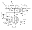
- FIG. 1 is a circuit diagram of a duplexer according to a first preferred embodiment of the present invention.
- FIG. 2 is a schematic plan view of the duplexer of the first preferred embodiment of the present invention.
- FIG. 3 is a diagram illustrating the isolation characteristics of the first preferred embodiment and a first comparative example.
- FIG. 4 is a diagram illustrating the attenuation frequency characteristics of the reception filters of the first preferred embodiment and the first comparative example.
- FIG. 5 is a diagram illustrating the attenuation frequency characteristics of the reception filters of the first preferred embodiment and the first comparative example.
- FIG. 6 is a circuit diagram of a duplexer of a second comparative example.
- FIG. 7 is a diagram illustrating the isolation characteristics of the first comparative example and the second comparative example.
- FIG. 8 is a diagram illustrating the filter characteristics of transmission filters in the duplexers of the first and second comparative examples.
- FIG. 9 is a diagrams illustrating the filter characteristics of the transmission filters in the duplexers of the first and second comparative examples.
- FIG. 10 is a circuit diagram of a duplexer according to a second preferred embodiment of the present invention.
- FIG. 11 is a schematic plan view of a first modification of the duplexer according to the first preferred embodiment of the present invention.
- FIG. 12 is a circuit diagram of a second modification of the duplexer according to the first preferred embodiment of the present invention.
- FIG. 13 is a circuit diagram of a third modification of the duplexer according to the first preferred embodiment of the present invention.
- FIG. 1 is a circuit diagram of a duplexer according to a first preferred embodiment of the present invention.
- FIG. 2 is a schematic plan view of the duplexer of the present preferred embodiment.
- a duplexer 1 includes an antenna terminal 2 , a transmission terminal 3 , and a reception terminal 4 .
- a transmission filter 5 is connected between the antenna terminal and the transmission terminal 3 .
- the transmission filter 5 includes a ladder filter.
- the transmission filter 5 includes a plurality of series-arm resonators S 1 a , S 1 b , S 1 c to S 5 a , and S 5 b which are arranged in this order from the transmission terminal 3 side.
- the plurality of first series-arm resonators S 1 a , S 1 b , S 1 c to S 5 a , and S 5 b are connected in series with one another on a series arm connecting the antenna terminal 2 to the transmission terminal 3 .
- First to fourth parallel arms are connected between the series arm and a ground potential.
- the first to fourth parallel arms are arranged in such a manner that the first parallel arm is near the transmission terminal 3 and the fourth parallel arm is far from the transmission terminal 3 .
- Parallel arm resonators P 1 a and P 1 b are connected in series with one another on the first parallel arm.
- One end of the parallel arm resonator P 1 a is connected to a connection node between the series-arm resonator S 1 c and the series-arm resonator S 2 .
- the parallel arm resonator P 1 b is connected to the ground potential through an inductor L 2 .
- the second parallel arm is connected between a connection node between the series-arm resonator S 2 and the series-arm resonator S 3 a and an inductor L 1 .
- a parallel arm resonator P 2 a and a parallel arm resonator P 2 b are connected in series with each other on the second parallel arm.
- the third parallel arm is connected between a connection node between the series-arm resonator S 3 c and the series-arm resonator S 4 a and the ground potential.
- a parallel arm resonator P 3 is provided on the third parallel arm.
- the parallel arm resonator P 3 is connected to the ground potential through the inductor L 1 .
- the fourth parallel arm is connected between a connection node between the series-arm resonator S 4 b and the series-arm resonator S 5 a and the ground potential.
- a parallel arm resonator P 4 is provided on the fourth parallel arm.
- the ground-potential-side end portion of the parallel arm resonator P 4 , the parallel arm resonator P 2 b , and the parallel arm resonator P 3 are connected to one another and are connected to the inductor L 1 .
- the parallel arm resonators P 1 a to P 4 are first parallel arm resonators.
- a reception filter 6 is connected between the antenna terminal 2 and the reception terminal 4 .
- the reception filter 6 includes a ladder filter portion 7 and a longitudinally coupled resonator-type surface acoustic wave filter 8 .
- One end of the ladder filter portion 7 is connected to the antenna terminal 2 , and the other end is connected to the longitudinally coupled resonator-type surface acoustic wave filter 8 .
- the ladder filter portion 7 includes series arm resonators S 11 a to S 11 c and S 12 defining and functioning as second series arm resonators, and parallel arm resonators P 11 a and P 11 b defining and functioning as second parallel arm resonators.
- the ladder filter portion 7 may include five or more of the second series arm resonators.
- three or more of the second parallel arm resonators may be provided.
- a plurality of parallel arms including parallel arm resonators may be provided.
- the longitudinally coupled resonator-type surface acoustic wave filter 8 defines a band pass filter portion.
- the longitudinally coupled resonator-type surface acoustic wave filter 8 is an unbalanced-type filter device, a longitudinally coupled resonator-type surface acoustic wave filter having a balanced-unbalanced transforming function may be used.
- One end of the longitudinally coupled resonator-type surface acoustic wave filter 8 is connected to the ladder filter portion 7 and the other end is connected to the reception terminal 4 .
- elastic wave resonators 9 a and 9 b are connected between the ground potential and a connection node between the reception terminal 4 and the longitudinally coupled resonator-type surface acoustic wave filter 8 .
- the duplexer 1 of the present preferred embodiment includes a coupling capacitor 11 illustrated in FIG. 1 .
- the coupling capacitor 11 is connected between a wiring line 12 , which connects the second series arm resonator S 11 c to the second series arm resonator S 12 in the ladder filter portion 7 , and the end portion of the inductor L 1 nearer to the parallel arm resonators P 2 b , P 3 , and P 4 .
- a piezoelectric substrate 13 is included in the duplexer 1 , as illustrated in FIG. 2 .
- a piezoelectric monocrystal substrate made of, for example, LiNbO 3 or LiTaO 3 may be used as the piezoelectric substrate 13 .
- a piezoelectric ceramic or the like may be used.
- the piezoelectric substrate 13 may be a substrate which is formed in such a manner that a high-acoustic-velocity layer is stacked on a support substrate, a low-acoustic-velocity layer is stacked on the high-acoustic-velocity layer, and a piezoelectric layer is stacked on this low-acoustic-velocity layer.
- the high-acoustic-velocity layer is one in which the acoustic velocity of a propagating bulk wave is higher than the acoustic velocity of an elastic wave propagating in the piezoelectric layer
- the low-acoustic-velocity layer is one in which the acoustic velocity of a propagating bulk wave is lower than the acoustic velocity of a bulk wave propagating in the piezoelectric layer.
- the series-arm resonators S 1 a to S 5 b and the parallel arm resonators P 1 a to P 4 illustrated in FIG. 1 are defined by one-port surface acoustic wave resonators.
- the one-port surface acoustic wave resonator includes an interdigital transducer (IDT) electrode and reflectors arranged on the two sides of the IDT electrode in the propagation direction of the surface acoustic wave, as is well known.
- IDT interdigital transducer
- FIG. 2 a rectangular shape with a cross mark therein indicates an IDT electrode or a reflector.
- the series-arm resonators S 1 a to S 5 b and the parallel arm resonators P 1 a to P 4 are connected to the antenna terminal 2 and between the transmission terminal 3 and the ground terminals 14 a and 14 b.
- the inductor L 1 is connected between the ground terminal 14 b and the ground potential.
- the inductor L 1 is externally connected to the structure illustrated in FIG. 2 .
- the inductor L 2 is externally connected in such a manner that one end thereof is connected to the ground terminal 14 a .
- the inductors L 1 and L 2 can be formed by connecting inductor devices or bonding wires having an inductance component to the ground terminals 14 a and 14 b , for example.
- a symbol which is a rectangular shape with a cross mark therein similarly indicates a portion in which an IDT electrode or a reflector is formed.
- the coupling capacitor 11 is provided between the wiring line 12 connecting the series arm resonator S 11 c to the series arm resonator S 12 and the ground terminal 14 b.
- the coupling capacitor 11 of the present preferred embodiment is defined by a capacitor device including a pair of comb-shaped electrodes.
- the pair of comb-shaped electrodes can be easily formed preferably by using a thin film formation method similarly to other wiring lines.
- the coupling capacitor 11 described above can be easily formed.
- the electrostatic capacitance of a coupling capacitor is easily adjusted by changing the number of the comb-shaped electrodes or the width of the electrode fingers.
- the coupling capacitor 11 may include other capacitor devices according to other preferred embodiments of the present invention. Further, the coupling capacitor 11 may be provide with various structures that allow electrostatic capacitance to be generated, and is not limited to a capacitor device.
- the ground terminal 14 b corresponds to a portion connected to the parallel arm resonator P 4 and the inductor L 1 .
- the coupling capacitor 11 is connected between the wiring line 12 and the end portion of the inductor L 1 nearer to the parallel arm resonators P 2 b , P 3 , and P 4 .
- a direction in which the electrode fingers extend is the same as a direction in which a surface acoustic wave propagates on the piezoelectric substrate 13 .
- directions in which the electrode fingers of IDT electrodes extend in the series-arm resonators S 1 a to S 5 b , the parallel arm resonators P 1 a to P 4 , the ladder filter portion 7 , and the longitudinally coupled resonator-type surface acoustic wave filter 8 are preferably the same.
- the direction in which the electrode fingers in the pair of comb-shaped electrodes extend is perpendicular or substantially perpendicular to the direction in which the electrode fingers in the IDT electrodes described above extend.
- a direction in which the electrode fingers of the comb-shaped electrode extend be different from a direction in which the electrode fingers of the IDT electrodes extend, and more preferably, be different by 90 degrees as in the present preferred embodiment, although not specifically limited. This allows an influence from a surface acoustic wave excited by the pair of comb-shaped electrodes to be reduced.
- the coupling capacitor 11 has a structure as described above in the duplexer 1 of the present preferred embodiment, the isolation characteristics in a transmission band and the attenuation near the pass band of a reception filter are sufficiently enhanced. This will be described below on the basis of a specific example.
- duplexer 1 having the specifications described below was produced.
- Piezoelectric Substrate 13 LiTaO 3 Substrate
- Table 1 shows the specifications of the series-arm resonators S 1 a , S 1 b , S 1 c to S 5 a , and S 5 b and the specifications of the parallel arm resonators P 1 a to P 4 .
- Inductor devices of 0.2 nH and 0.4 nH were connected as the inductors L 1 and L 2 .
- Table 2 shows the specifications of the series arm resonators S 11 a to S 11 c and S 12 and the parallel arm resonators P 11 a and P 11 b .
- the details of the longitudinally coupled resonator-type surface acoustic wave filter 8 are as follows.
- Table 4 and Table 5 show the specifications of the longitudinally coupled resonator-type surface acoustic wave filter 8 . Note that the duty ratios of all the reflectors and IDTs were set to 0.5. The overlap width was set to 40 ⁇ m. The number of electrode fingers of a reflector was set to 75.
- a pair of comb-shaped electrodes having an electrostatic capacitance of 0.25 pF was formed as the coupling capacitor 11 .
- An Al layer including Cu was used as an electrode layer.
- a duplexer of a first comparative example configured similarly to the example described above except that the coupling capacitor 11 is not provided was formed.
- FIG. 3 The isolation characteristics of duplexers of the example and the first comparative example prepared in the manner described above are illustrated in FIG. 3 .
- FIG. 4 and FIG. 5 illustrate the attenuation frequency characteristics of the reception filters in the example and the first comparative example.
- isolation in the pass band of the reception filter according to the example is considerably improved, compared with the first comparative example.
- the insertion loss in the example within the pass band of the transmission filter is not substantially different from the first comparative example. Further, it can be seen that the positions, in terms of frequency, of the attenuation poles outside of the pass band negligibly change.
- a duplexer 101 having a circuit configuration illustrated in FIG. 6 was prepared as a second comparative example.
- the coupling capacitor 11 is connected between the antenna terminal 2 and the end portion of the inductor L 1 nearer to the parallel arm resonators P 1 and P 2 .
- FIG. 7 is a diagram illustrating the isolation characteristics of the second comparative example prepared as described above and the first comparative example which does not include the coupling capacitor 11 .
- FIG. 8 and FIG. 9 are diagrams illustrating the attenuation frequency characteristics of the transmission filters of the first and second comparative examples.
- the electrostatic capacitance of the coupling capacitor 11 in the second comparative example was set to 0.5 pF.
- the isolation in the pass band of the reception filter has been improved but the loss within the pass band of the transmission filter has been degraded, in the second comparative example.
- the position, in terms of frequency, of the attenuation poles outside of the pass band of the transmission filter have shifted and, hence, the attenuation characteristics have been degraded.
- the ladder filter portion 7 is provided between the antenna terminal and the longitudinally coupled resonator-type surface acoustic wave filter, and the coupling capacitor 11 is provided between the wiring line 12 connecting the series arm resonators S 11 c and S 12 of the ladder filter portion 7 to each other and the inductor L 1 .
- a current flows to the reception filter side because the coupling capacitor 11 is provided between the reception filter and the transmission filter.
- the coupling capacitor 11 is unlikely to influence the transmission filter.
- degradation of the impedance matching in the transmission filter is unlikely to be generated.
- a shift in the positions, in terms of frequency, of the attenuation poles outside of the pass band of the transmission filter is effectively reduced or prevented.
- an elastic wave resonator 32 is included instead of the coupling capacitor 11 .
- the elastic wave resonator 32 preferably is a one-port-type surface acoustic wave resonator, but may be a boundary acoustic wave resonator.
- the rest of the configuration of the second preferred embodiment is approximately the same as that of the first preferred embodiment, although slightly different from the first preferred embodiment in terms of, for example, the configuration of the ladder filter portion 7 .
- Series-arm resonators S 1 a and S 1 b to S 4 are connected in series to the antenna terminal 2 in this order. Note that identical portions are denoted by the same reference symbols and descriptions thereof are omitted.
- the elastic wave resonator 32 instead of the coupling capacitor 11 , may be connected between the wiring line 12 and the end portion of the inductor L 1 nearer to the parallel arm resonators P 1 and P 2 .
- an elastic wave resonator 22 when an elastic wave resonator 22 is connected in such a manner as to function as a capacitor, isolation in a reception band is improved similarly to the first preferred embodiment described above.
- an increase in loss within a pass band in the transmission filter is suppressed or prevented and, further, a shift of the positions, in terms of frequency, of attenuation poles outside of the pass band of the transmission filter is suppressed or prevented.
- FIG. 11 is a schematic plan view of a duplexer according to a first modification of the first preferred embodiment of the present invention.
- the coupling capacitor 11 includes a capacitor-forming electrode portion 12 a connected to the wiring line 12 and a capacitor-forming electrode portion 23 facing the capacitor-forming electrode portion 12 a with a gap therebetween, instead of a pair of comb-shaped electrodes.
- the capacitor-forming electrode portion 23 is connected to a wiring line 17 connected to the ground terminal 14 b .
- the coupling capacitor 11 may include electrode patterns facing each other with a gap therebetween instead of a pair of comb-shaped electrodes.
- the coupling capacitor 11 may be the capacitor-forming electrode portions 12 a and 23 described above in the case of a small electrostatic capacitance.
- FIG. 12 is a circuit diagram illustrating a second modification of the first preferred embodiment of the present invention.
- the coupling capacitor 11 is connected between the wiring line 12 and the end portion of the inductor L 2 nearer to the parallel arm resonator P 3 , rather than connected to the inductor L 1 .
- the coupling capacitor 11 may be connected to the end portion of the inductor L 2 nearer to the parallel arm resonator P 3 rather than to the inductor L 1 .
- an inductor including an end portion connected to a coupling capacitor is not specifically limited as long as the inductor is connected between a parallel arm resonator and the ground potential.
- the coupling capacitor 11 be connected to the inductor L 1 closest to the antenna terminal. This further enhances the isolation characteristics.
- FIG. 13 is a circuit diagram illustrating a third modification of the duplexer of the first preferred embodiment of the present invention.
- a longitudinally coupled resonator-type surface acoustic wave filter 52 including first to fourth longitudinally coupled resonator-type surface acoustic wave filter portions 52 a to 52 d is used, instead of the longitudinally coupled resonator-type surface acoustic wave filter 8 .
- the longitudinally coupled resonator-type surface acoustic wave filter portions 52 a to 52 d are all three-IDT longitudinally coupled resonator-type surface acoustic wave filter portions.
- a preferred embodiment of a longitudinally coupled resonator-type surface acoustic wave filter portion is not specifically limited as long as it has a configuration in which two or more IDTs sandwiched between two reflectors are arranged in the propagation direction of a surface acoustic wave.
- it may be a longitudinally coupled resonator-type surface acoustic wave filter portion including five IDTs.
- each of the longitudinally coupled resonator-type surface acoustic wave filter portions defining a reception filter is not specifically limited.
- the reception filter may include longitudinally coupled resonator-type surface acoustic wave filters having a balanced-unbalanced transforming function. In that case, first and second balanced terminals constitute a reception terminal.
- a ladder filter defining a transmission filter in a duplexer is not limited to the preferred embodiments and modifications described above either. In other words, a ladder filter having any number of stages may be included. However, it is preferably to include a ladder filter having a configuration in which an inductor is connected between a parallel arm resonator and a ground potential. A coupling capacitor or an elastic wave resonator preferably is connected between one end of the inductor and the wiring line 12 described above.
Landscapes
- Physics & Mathematics (AREA)
- Acoustics & Sound (AREA)
- Surface Acoustic Wave Elements And Circuit Networks Thereof (AREA)
Applications Claiming Priority (3)
| Application Number | Priority Date | Filing Date | Title |
|---|---|---|---|
| JP2013191982 | 2013-09-17 | ||
| JP2013-191982 | 2013-09-17 | ||
| PCT/JP2014/067180 WO2015040922A1 (fr) | 2013-09-17 | 2014-06-27 | Duplexeur |
Related Parent Applications (1)
| Application Number | Title | Priority Date | Filing Date |
|---|---|---|---|
| PCT/JP2014/067180 Continuation WO2015040922A1 (fr) | 2013-09-17 | 2014-06-27 | Duplexeur |
Publications (2)
| Publication Number | Publication Date |
|---|---|
| US20160173062A1 US20160173062A1 (en) | 2016-06-16 |
| US9806693B2 true US9806693B2 (en) | 2017-10-31 |
Family
ID=52688582
Family Applications (1)
| Application Number | Title | Priority Date | Filing Date |
|---|---|---|---|
| US15/051,828 Active 2034-09-02 US9806693B2 (en) | 2013-09-17 | 2016-02-24 | Duplexer with a ladder filter portion and a specifically connected capacitor or elastic wave resonator |
Country Status (4)
| Country | Link |
|---|---|
| US (1) | US9806693B2 (fr) |
| JP (1) | JP5765502B1 (fr) |
| CN (1) | CN105531927B (fr) |
| WO (1) | WO2015040922A1 (fr) |
Cited By (1)
| Publication number | Priority date | Publication date | Assignee | Title |
|---|---|---|---|---|
| US20210083651A1 (en) * | 2019-09-18 | 2021-03-18 | Murata Manufacturing Co., Ltd. | Filter device |
Families Citing this family (19)
| Publication number | Priority date | Publication date | Assignee | Title |
|---|---|---|---|---|
| JP5765501B1 (ja) * | 2013-09-17 | 2015-08-19 | 株式会社村田製作所 | デュプレクサ |
| DE102014110905A1 (de) * | 2014-07-31 | 2016-02-04 | Epcos Ag | Duplexer mit verbesserter Reflektivität |
| WO2017221548A1 (fr) * | 2016-06-24 | 2017-12-28 | 株式会社村田製作所 | Dispositif de filtrage d'ondes acoustiques |
| CN209881752U (zh) * | 2016-11-08 | 2019-12-31 | 株式会社村田制作所 | 弹性波滤波器装置以及多工器 |
| DE102018102891A1 (de) * | 2017-02-13 | 2018-08-16 | Murata Manufacturing Co., Ltd. | Multiplexierer, Übertragungsvorrichtung und Empfangsvorrichtung |
| JP6702278B2 (ja) * | 2017-07-05 | 2020-06-03 | 株式会社村田製作所 | マルチプレクサ |
| CN111512548B (zh) | 2017-12-27 | 2021-02-09 | 株式会社村田制作所 | 弹性波滤波器、多工器、高频前端电路以及通信装置 |
| WO2019172032A1 (fr) * | 2018-03-08 | 2019-09-12 | 株式会社村田製作所 | Multiplexeur, circuit frontal à haute fréquence et dispositif de communication |
| US11108379B2 (en) * | 2018-09-05 | 2021-08-31 | Resonant Inc. | High isolation surface acoustic wave duplexer |
| CN109831174A (zh) * | 2018-11-28 | 2019-05-31 | 天津大学 | 一种双工器 |
| CN111342793B (zh) * | 2018-12-18 | 2023-09-26 | 天津大学 | 带通滤波器及提高其抑制水平的方法、双工器和电子设备 |
| JP7136026B2 (ja) * | 2019-07-16 | 2022-09-13 | 株式会社村田製作所 | マルチプレクサ |
| CN111064447B (zh) * | 2019-11-15 | 2023-12-15 | 天津大学 | 一种双工器 |
| WO2022044810A1 (fr) * | 2020-08-24 | 2022-03-03 | 株式会社村田製作所 | Dispositif de filtre d'ondes élastiques composite |
| JPWO2022092315A1 (fr) * | 2020-11-02 | 2022-05-05 | ||
| KR20220118137A (ko) | 2021-02-18 | 2022-08-25 | (주)와이솔 | 듀플렉서 |
| CN112994643B (zh) * | 2021-05-18 | 2022-04-19 | 成都频岢微电子有限公司 | 一种高隔离度及防进胶saw双工器 |
| CN115955257B (zh) * | 2023-02-14 | 2023-05-19 | 成都频岢微电子有限公司 | 一种高隔离度的压电声波双工器 |
| CN116318037B (zh) * | 2023-05-15 | 2023-09-22 | 成都频岢微电子有限公司 | 声表面波谐振器、滤波器以及双工器 |
Citations (12)
| Publication number | Priority date | Publication date | Assignee | Title |
|---|---|---|---|---|
| JP2004096250A (ja) | 2002-08-29 | 2004-03-25 | Murata Mfg Co Ltd | 弾性表面波フィルタ、通信装置 |
| JP2006186433A (ja) | 2004-12-24 | 2006-07-13 | Nippon Dempa Kogyo Co Ltd | 弾性表面波フィルタ |
| JP2007258832A (ja) | 2006-03-20 | 2007-10-04 | Kyocera Corp | 弾性表面波素子、弾性表面波装置、弾性表面波装置の製造方法、通信装置、送信装置および受信装置 |
| US20080007370A1 (en) * | 2004-04-16 | 2008-01-10 | Shozo Matsumoto | Balanced Surface Acoustic Wave Filter |
| JP2010192974A (ja) * | 2009-02-16 | 2010-09-02 | Ube Ind Ltd | 分波器 |
| US20100244979A1 (en) * | 2008-12-26 | 2010-09-30 | Fujitsu Limited | Duplexer, substrate for duplexer, and electronic apparatus |
| US20110018654A1 (en) * | 2009-07-27 | 2011-01-27 | Avago Technologies Wireless Ip (Singapore) Pte. Ltd. | Resonator filter with multiple cross-couplings |
| WO2011061904A1 (fr) | 2009-11-19 | 2011-05-26 | パナソニック株式会社 | Dispositif à filtre d'onde élastique, et duplexeur d'antenne l'utilisant |
| WO2012063517A1 (fr) | 2010-11-09 | 2012-05-18 | 株式会社村田製作所 | Dispositif de filtre à ondes acoustiques |
| WO2012105337A1 (fr) | 2011-01-31 | 2012-08-09 | 京セラ株式会社 | Filtre de branchement et composant de module de communication |
| US20140010122A1 (en) * | 2010-12-22 | 2014-01-09 | Epcos Ag | Reactance filter comprising suppression in the stop band and duplexer component |
| US20160173061A1 (en) * | 2013-09-17 | 2016-06-16 | Murata Manufacturing Co., Ltd. | Duplexer |
Family Cites Families (5)
| Publication number | Priority date | Publication date | Assignee | Title |
|---|---|---|---|---|
| JP3419339B2 (ja) * | 1999-03-11 | 2003-06-23 | 株式会社村田製作所 | 弾性表面波フィルタ、デュプレクサ、通信機装置 |
| JP3414370B2 (ja) * | 1999-08-11 | 2003-06-09 | 株式会社村田製作所 | 弾性表面波フィルタ、デュプレクサ、通信機装置 |
| KR101129107B1 (ko) * | 2007-12-11 | 2012-03-23 | 가부시키가이샤 무라타 세이사쿠쇼 | 표면파 장치 및 듀플렉서 |
| JP5185057B2 (ja) * | 2008-10-17 | 2013-04-17 | 日本電波工業株式会社 | デュプレクサ |
| JP5240793B2 (ja) * | 2009-03-09 | 2013-07-17 | 日本電波工業株式会社 | デュプレクサ |
-
2014
- 2014-06-27 WO PCT/JP2014/067180 patent/WO2015040922A1/fr active Application Filing
- 2014-06-27 CN CN201480050528.8A patent/CN105531927B/zh active Active
- 2014-06-27 JP JP2015503382A patent/JP5765502B1/ja active Active
-
2016
- 2016-02-24 US US15/051,828 patent/US9806693B2/en active Active
Patent Citations (15)
| Publication number | Priority date | Publication date | Assignee | Title |
|---|---|---|---|---|
| JP2004096250A (ja) | 2002-08-29 | 2004-03-25 | Murata Mfg Co Ltd | 弾性表面波フィルタ、通信装置 |
| US20040080384A1 (en) | 2002-08-29 | 2004-04-29 | Mitsuo Takeda | Surface acoustic wave filter and communication device |
| US20080007370A1 (en) * | 2004-04-16 | 2008-01-10 | Shozo Matsumoto | Balanced Surface Acoustic Wave Filter |
| JP2006186433A (ja) | 2004-12-24 | 2006-07-13 | Nippon Dempa Kogyo Co Ltd | 弾性表面波フィルタ |
| JP2007258832A (ja) | 2006-03-20 | 2007-10-04 | Kyocera Corp | 弾性表面波素子、弾性表面波装置、弾性表面波装置の製造方法、通信装置、送信装置および受信装置 |
| US20100244979A1 (en) * | 2008-12-26 | 2010-09-30 | Fujitsu Limited | Duplexer, substrate for duplexer, and electronic apparatus |
| JP2010192974A (ja) * | 2009-02-16 | 2010-09-02 | Ube Ind Ltd | 分波器 |
| US20110018654A1 (en) * | 2009-07-27 | 2011-01-27 | Avago Technologies Wireless Ip (Singapore) Pte. Ltd. | Resonator filter with multiple cross-couplings |
| WO2011061904A1 (fr) | 2009-11-19 | 2011-05-26 | パナソニック株式会社 | Dispositif à filtre d'onde élastique, et duplexeur d'antenne l'utilisant |
| US20120313724A1 (en) | 2009-11-19 | 2012-12-13 | Panasonic Corporation | Elastic wave filter device and antenna duplexer using same |
| WO2012063517A1 (fr) | 2010-11-09 | 2012-05-18 | 株式会社村田製作所 | Dispositif de filtre à ondes acoustiques |
| US20140010122A1 (en) * | 2010-12-22 | 2014-01-09 | Epcos Ag | Reactance filter comprising suppression in the stop band and duplexer component |
| WO2012105337A1 (fr) | 2011-01-31 | 2012-08-09 | 京セラ株式会社 | Filtre de branchement et composant de module de communication |
| US20130307639A1 (en) | 2011-01-31 | 2013-11-21 | Kyocera Corporation | Branching filter and communication module component |
| US20160173061A1 (en) * | 2013-09-17 | 2016-06-16 | Murata Manufacturing Co., Ltd. | Duplexer |
Non-Patent Citations (1)
| Title |
|---|
| Official Communication issued in International Application PCT/JP2014/067180, dated Sep. 9, 2014. |
Cited By (2)
| Publication number | Priority date | Publication date | Assignee | Title |
|---|---|---|---|---|
| US20210083651A1 (en) * | 2019-09-18 | 2021-03-18 | Murata Manufacturing Co., Ltd. | Filter device |
| US11677382B2 (en) * | 2019-09-18 | 2023-06-13 | Murata Manufacturing Co., Ltd. | Filter device |
Also Published As
| Publication number | Publication date |
|---|---|
| US20160173062A1 (en) | 2016-06-16 |
| CN105531927B (zh) | 2018-03-30 |
| CN105531927A (zh) | 2016-04-27 |
| JPWO2015040922A1 (ja) | 2017-03-02 |
| JP5765502B1 (ja) | 2015-08-19 |
| WO2015040922A1 (fr) | 2015-03-26 |
Similar Documents
| Publication | Publication Date | Title |
|---|---|---|
| US9806693B2 (en) | Duplexer with a ladder filter portion and a specifically connected capacitor or elastic wave resonator | |
| US9762209B2 (en) | Duplexer with a series trap element and a specifically connected capacitance or elastic wave resonator | |
| KR101914890B1 (ko) | 래더형 필터, 탄성파 필터 모듈 및 듀플렉서 | |
| JP6330910B2 (ja) | デュプレクサ | |
| US8319585B2 (en) | Elastic wave filter device and module including the same | |
| JP2019036856A (ja) | マルチプレクサ | |
| JP2010011300A (ja) | 共振器、該共振器を用いるフィルタ及びデュプレクサ | |
| JP5700121B2 (ja) | 弾性波フィルタ装置 | |
| US7868716B2 (en) | Acoustic wave filter apparatus | |
| JP6773238B2 (ja) | 弾性波フィルタ、マルチプレクサ、高周波フロントエンド回路および通信装置 | |
| JPWO2011061904A1 (ja) | 弾性波フィルタ装置とこれを用いたアンテナ共用器 | |
| JPWO2012056767A1 (ja) | 弾性波分波器 | |
| JP5018894B2 (ja) | 弾性波フィルタ装置 | |
| WO2018096799A1 (fr) | Dispositif de filtre et multiplexeur | |
| US8791774B2 (en) | Branching filter | |
| JP2012244551A (ja) | デュプレクサの受信側フィルタ及びデュプレクサ | |
| WO2018235689A1 (fr) | Dispositif de filtrage d'ondes acoustiques, dispositif filtre composite et multiplexeur | |
| CN112290906B (zh) | 滤波器及多工器 | |
| CN116210155A (zh) | 多工器 | |
| JP2019165435A (ja) | 複合マルチプレクサ | |
| CN112204881A (zh) | 多工器 |
Legal Events
| Date | Code | Title | Description |
|---|---|---|---|
| AS | Assignment |
Owner name: MURATA MANUFACTURING CO., LTD., JAPAN Free format text: ASSIGNMENT OF ASSIGNORS INTEREST;ASSIGNOR:TAKAMINE, YUICHI;REEL/FRAME:037811/0956 Effective date: 20160218 |
|
| STCF | Information on status: patent grant |
Free format text: PATENTED CASE |
|
| MAFP | Maintenance fee payment |
Free format text: PAYMENT OF MAINTENANCE FEE, 4TH YEAR, LARGE ENTITY (ORIGINAL EVENT CODE: M1551); ENTITY STATUS OF PATENT OWNER: LARGE ENTITY Year of fee payment: 4 |