US9806682B1 - Multilevel class-D amplifiers - Google Patents

Multilevel class-D amplifiers Download PDF

Info

Publication number
US9806682B1
US9806682B1 US15/049,534 US201615049534A US9806682B1 US 9806682 B1 US9806682 B1 US 9806682B1 US 201615049534 A US201615049534 A US 201615049534A US 9806682 B1 US9806682 B1 US 9806682B1
Authority
US
United States
Prior art keywords
boost
output
output stage
multilevel
pair
Prior art date
Legal status (The legal status is an assumption and is not a legal conclusion. Google has not performed a legal analysis and makes no representation as to the accuracy of the status listed.)
Active
Application number
US15/049,534
Inventor
Bruno Marcone
Francesco Rezzi
Current Assignee (The listed assignees may be inaccurate. Google has not performed a legal analysis and makes no representation or warranty as to the accuracy of the list.)
Marvell Asia Pte Ltd
Original Assignee
Marvell International Ltd
Priority date (The priority date is an assumption and is not a legal conclusion. Google has not performed a legal analysis and makes no representation as to the accuracy of the date listed.)
Filing date
Publication date
Application filed by Marvell International Ltd filed Critical Marvell International Ltd
Priority to US15/049,534 priority Critical patent/US9806682B1/en
Assigned to MARVELL INTERNATIONAL LTD. reassignment MARVELL INTERNATIONAL LTD. ASSIGNMENT OF ASSIGNORS INTEREST (SEE DOCUMENT FOR DETAILS). Assignors: MARVELL ITALIA S.R.L.
Assigned to MARVELL ITALIA S.R.L. reassignment MARVELL ITALIA S.R.L. ASSIGNMENT OF ASSIGNORS INTEREST (SEE DOCUMENT FOR DETAILS). Assignors: MARCONE, BRUNO, REZZI, FRANCESCO
Application granted granted Critical
Publication of US9806682B1 publication Critical patent/US9806682B1/en
Assigned to CAVIUM INTERNATIONAL reassignment CAVIUM INTERNATIONAL ASSIGNMENT OF ASSIGNORS INTEREST (SEE DOCUMENT FOR DETAILS). Assignors: MARVELL INTERNATIONAL LTD.
Assigned to MARVELL ASIA PTE, LTD. reassignment MARVELL ASIA PTE, LTD. ASSIGNMENT OF ASSIGNORS INTEREST (SEE DOCUMENT FOR DETAILS). Assignors: CAVIUM INTERNATIONAL
Active legal-status Critical Current
Anticipated expiration legal-status Critical

Links

Images

Classifications

    • HELECTRICITY
    • H03ELECTRONIC CIRCUITRY
    • H03FAMPLIFIERS
    • H03F3/00Amplifiers with only discharge tubes or only semiconductor devices as amplifying elements
    • H03F3/45Differential amplifiers
    • H03F3/45071Differential amplifiers with semiconductor devices only
    • H03F3/45076Differential amplifiers with semiconductor devices only characterised by the way of implementation of the active amplifying circuit in the differential amplifier
    • H03F3/45475Differential amplifiers with semiconductor devices only characterised by the way of implementation of the active amplifying circuit in the differential amplifier using IC blocks as the active amplifying circuit
    • HELECTRICITY
    • H03ELECTRONIC CIRCUITRY
    • H03FAMPLIFIERS
    • H03F3/00Amplifiers with only discharge tubes or only semiconductor devices as amplifying elements
    • H03F3/181Low frequency amplifiers, e.g. audio preamplifiers
    • H03F3/183Low frequency amplifiers, e.g. audio preamplifiers with semiconductor devices only
    • H03F3/185Low frequency amplifiers, e.g. audio preamplifiers with semiconductor devices only with field-effect devices
    • HELECTRICITY
    • H03ELECTRONIC CIRCUITRY
    • H03FAMPLIFIERS
    • H03F3/00Amplifiers with only discharge tubes or only semiconductor devices as amplifying elements
    • H03F3/20Power amplifiers, e.g. Class B amplifiers, Class C amplifiers
    • H03F3/21Power amplifiers, e.g. Class B amplifiers, Class C amplifiers with semiconductor devices only
    • H03F3/213Power amplifiers, e.g. Class B amplifiers, Class C amplifiers with semiconductor devices only in integrated circuits
    • HELECTRICITY
    • H03ELECTRONIC CIRCUITRY
    • H03FAMPLIFIERS
    • H03F3/00Amplifiers with only discharge tubes or only semiconductor devices as amplifying elements
    • H03F3/20Power amplifiers, e.g. Class B amplifiers, Class C amplifiers
    • H03F3/21Power amplifiers, e.g. Class B amplifiers, Class C amplifiers with semiconductor devices only
    • H03F3/217Class D power amplifiers; Switching amplifiers
    • H03F3/2171Class D power amplifiers; Switching amplifiers with field-effect devices
    • HELECTRICITY
    • H03ELECTRONIC CIRCUITRY
    • H03FAMPLIFIERS
    • H03F2200/00Indexing scheme relating to amplifiers
    • H03F2200/351Pulse width modulation being used in an amplifying circuit
    • HELECTRICITY
    • H03ELECTRONIC CIRCUITRY
    • H03FAMPLIFIERS
    • H03F2200/00Indexing scheme relating to amplifiers
    • H03F2200/48Indexing scheme relating to amplifiers the output of the amplifier being coupled out by a capacitor
    • HELECTRICITY
    • H03ELECTRONIC CIRCUITRY
    • H03FAMPLIFIERS
    • H03F2203/00Indexing scheme relating to amplifiers with only discharge tubes or only semiconductor devices as amplifying elements covered by H03F3/00
    • H03F2203/45Indexing scheme relating to differential amplifiers
    • H03F2203/45138Two or more differential amplifiers in IC-block form are combined, e.g. measuring amplifiers

Definitions

  • the present disclosure is generally related to class-D amplifiers, and more specifically to multilevel class-D amplifiers.
  • a class-D amplifier also known as a switching amplifier, includes amplifying devices (e.g., field-effect transistors (FETs), metal-oxide FETs (MOSFETs), power MOSFETs) that are implemented as electronic switches, instead of as linear gain devices, as in linear amplifiers.
  • a class-D amplifier includes an input stage that uses, e.g., pulse-width modulation (PWM), to convert an input analog signal (to be amplified by the class-D amplifier) to a train of constant amplitude pulses having a variable duty cycle that is proportional to instantaneous values of the input analog signal.
  • PWM pulse-width modulation
  • the train of pulses also referred to as a PWM signal, is indicative of the input signal.
  • the class-D amplifier further includes an output stage that uses two pairs of high-voltage switches (e.g., power MOSFETs) which are driven by respective instances of the PWM signal and, when a load is coupled to output ports of the output stage, are arranged to form an output bridge.
  • the output stage delivers a constantly changing voltage into the coupled load as an amplified signal, which is an amplified replica of the PWM signal provided by the input stage.
  • a low-pass filter can remove high-frequency switching components of the amplified signal to recover information carried by the input analog signal, where the recovered information is to be used by the load.
  • V BAT voltage level
  • FIG. 9A shows an output stage of a class-D amplifier implemented in a conventional charge-pump configuration.
  • the output stage is driven by two PWM signals (LP and LM) indicative of an input analog signal, and uses a charge-pump circuit, powered by a voltage level V BAT , in conjunction with a fly capacitor C Fly and a tank capacitor C Tank .
  • the output bridge of the output stage is powered by a larger voltage level 2V BAT output by the charge-pump circuit.
  • FIG. 10A shows an output stage of a class-D amplifier implemented in a conventional DC-DC boosted configuration.
  • the output stage also is driven by two PWM signals (LP and LM) indicative of an input analog signal, but uses a DC-DC boost converter, powered by a voltage level V BAT through a boost inductor L BST .
  • an amplified signal V Load provided to the load, by the output stage implemented in the DC-DC boosted configuration, is a train of pulses having constant amplitude V BST , as shown in FIG. 10B .
  • an amplified signal V Load provided to the load, by the output stage implemented as a combination of charge-pump configuration and DC-DC boosted configuration is a train of pulses having constant amplitude 2V BST .
  • the amplified signal V Load (e.g., illustrated either in FIG. 9B or FIG. 10B ) provided to the load by the output stage, in either of the conventional configurations shown in FIG. 9A or FIG. 10A or in the noted conventional combination thereof, is always a single-level amplified signal.
  • implementations of a class-D amplifier are described that can be used to amplify an input analog signal and provide to a load a multilevel amplified signal having an amplitude larger than a voltage level of a power source used by the class-D amplifier.
  • the amplifier system includes a multilevel output stage powered with a voltage having a predetermined voltage level relative to ground; a multilevel modulator configured to form a plurality of pulse-width modulated (PWM) driving signals based on i) the input signal and ii) a square carrier signal. Additionally, the multilevel modulator is further configured to drive the multilevel output stage with the plurality of PWM driving signals.
  • the amplifier system further includes a pair of output ports coupled with the multilevel output stage; and a boost capacitor coupled with a first output port of the pair of output ports.
  • the multilevel output stage is configured to output, at the pair of output ports, when driven with the plurality of PWM driving signals, an output signal having a plurality of levels.
  • differences between adjacent levels of the output signal have a magnitude equal to the predetermined voltage level
  • an amplitude of the output signal is a non-unity integer multiple of the predetermined voltage level
  • the output signal varies over time between its multiple levels in accordance with the input signal.
  • the multilevel output stage can include four high-voltage (HV) switches, which form, when a load is coupled between the pair of output ports, an output bridge that includes the four HV switches and the load; and a boost bridge that includes a pair of the HV switches, a pair of low-voltage (LV) switches, and the boost capacitor.
  • HV high-voltage
  • LV low-voltage
  • the boost bridge is driven by a pair of PWM driving signals of the plurality of PWM driving signals.
  • the amplitude of the output signal can be twice the predetermined voltage level.
  • the multilevel output stage further can include a second boost capacitor coupled with a second output port of the pair of output ports; and a second boost bridge that includes a second pair of the HV switches, a second pair of LV switches, and the second boost capacitor.
  • the second boost bridge is driven by a second pair of PWM driving signals of the plurality of PWM driving signals.
  • the amplitude of the output signal can be three times the predetermined voltage level.
  • the amplifier system can include a power supply that provides the predetermined voltage level to the multilevel output stage.
  • the amplifier system can include a power supply that powers the boost stage through a boost inductor with a power supply voltage level smaller than the power supply voltage level, and causes the boost stage to provide the predetermined voltage level to the first and second boost bridges.
  • the multilevel modulator can include a fully differential integrator.
  • the multilevel modulator can include a differential input to receive the input signal.
  • the multilevel modulator can include four outputs through which respective four PWM driving signals are delivered to the multilevel output stage.
  • the amplifier circuitry includes (I) a multilevel modulator including (i) two modulator input ports, and (ii) four modulator output ports; and (II) a multilevel output stage including (i) four output stage input ports respectively coupled with the four modulator output ports, (ii) four output stage boost ports, (iii) a first pair of high-voltage (HV) switches connected to each other at a first one of the output stage boost ports, the first pair of HV switches having a first control terminal coupled to a first one of the output stage input ports, (iv) a second pair of HV switches connected to each other at a second one of the output stage boost ports, the second pair of HV switches having a second control terminal coupled to a second one of the output stage input ports, (v) a first pair of low-voltage (LV) switches connected to each other at a third one of the output stage boost ports, the first pair of LV switches having a third control terminal coupled to
  • an amplification system can include the foregoing integrated circuit chip including amplifier circuitry.
  • the amplification system further can include two amplifier input ports respectively coupled with the modulator input ports; and two amplifier output ports respectively coupled with the first output stage boost port and the second output stage boost port.
  • a load coupled between the two amplifier output ports causes formation of an output bridge that includes the first pair of HV switches, the second pair of HV switches and the load.
  • the amplifier system can include a boost capacitor having two terminals, one of the two terminals being coupled to the first output stage boost port, and another of the two terminals being coupled to the third output stage boost port, thereby forming a boost bridge that includes the first pair of HV switches, the first pair of LV switches and the boost capacitor.
  • the amplifier system can further include a second boost capacitor having two terminals, one of the two terminals of the second boost capacitor being coupled to the second output stage boost port and at the other one of the terminals of the second boost capacitor being coupled to the fourth output stage boost port, thereby forming a second boost bridge that includes the second pair of HV switches, the second pair of LV switches and the second boost capacitor.
  • the amplifier system can further include a power supply to power the multilevel output stage with a predetermined voltage level.
  • the amplification system can further include a boost inductor coupled with the boost stage input; and a power supply to power the boost stage through the boost inductor with a power supply voltage level.
  • the boost stage can power the multilevel output stage with a predetermined voltage level that is boosted relative to the power supply voltage level.
  • the multilevel modulator can include a fully differential integrator.
  • the multilevel modulator is configured perform, during operation of the integrated circuit chip including amplifier circuitry, operations including: (I) receive an input signal through the modulator input ports, (II) form four pulse-width modulated (PWM) drive signals based on (i) the input signal and (ii) a square carrier signal, and (III) provide the four PWM drive signals, through respective modulator output ports to respective output stage input ports, to drive the output stage.
  • PWM pulse-width modulated
  • An input stage and an output stage of the disclosed class-D amplifier can be formed on an integrated circuit (IC) chip, and the IC chip can be used in an amplification system configurable in accordance with specific use cases.
  • IC integrated circuit
  • V BAT 3.7V
  • the power delivered into an 8 ⁇ load is about 0.5 W.
  • a mid-level consumer electronics device e.g., a mid-range priced smartphone
  • the power delivered into an 8 ⁇ load is about 8 W.
  • the disclosed amplifier system can be less voluminous than, while delivering the same performance as, the foregoing conventional amplifier system.
  • an area of silicon required for the smaller, LV switches included in the boost stage of the IC chip of the disclosed class-D amplifier is smaller than an area of silicon required for the larger, HV switches included in the DC-DC boost convertor of the IC chip of the conventional class-D amplifier illustrated in FIG. 10A .
  • the IC chip of the disclosed class-D amplifier is less voluminous and consumes less power than the IC chip of the conventional class-D amplifier illustrated in FIG. 10A .
  • the multilevel output stage of the disclosed amplifier system has smaller output resistance R OUT than the output resistance R OUT,CP of the single-level output stage of the conventional charge-pump implementation of the class-D amplifier shown in FIG. 9A , and thus the disclosed amplifier system can transfer power more efficiently to a load than the noted conventional amplifier system.
  • Another benefit of using a multilevel output stage for the disclosed amplifier system is that the amplitude of the amplified signal output by the disclosed class-D amplifier varies in steps equal to a voltage level (e.g., V BAT ) of a power source used by the IC chip.
  • V BAT a voltage level of a power source used by the IC chip.
  • the conventional charge-pump implementation of the class-D amplifier illustrated in FIG. 9A uses a single-level output stage, and thus, the amplitude of the amplified signal output by the conventional charge-pump implementation of the class-D amplifier varies in steps equal to twice the voltage level V BAT (as shown in FIG. 9B ).
  • V BAT e.g., 3.7V
  • 2V BAT e.g., 7.4V
  • FIGS. 1A-1D show aspects of a multilevel class D amplifier that includes a multilevel modulator and a multilevel output stage.
  • FIG. 2 shows aspects of a multilevel output stage that provides a multilevel output signal with an amplitude equal to a non-unity integer multiple of a power supply voltage.
  • FIGS. 3A-3B show aspects of a multilevel output stage that provides an output signal with an amplitude equal to a power supply voltage.
  • FIGS. 4A-4B show aspects of a multilevel output stage that provides a multilevel output signal with an amplitude equal to twice a power supply voltage.
  • FIGS. 5A-5B show aspects of a multilevel output stage that provides a multilevel output signal with an amplitude equal to three times a power supply voltage.
  • FIGS. 6A-6B show aspects of a multilevel output stage that provides a multilevel output signal with an amplitude equal to three times a boosted power supply voltage.
  • FIG. 7 shows an example of a multilevel modulator.
  • FIG. 8 shows aspects of signals formed inside, and aspects of pulse-width modulated (PWM) driving signals output by, the multilevel modulator from FIG. 7 .
  • PWM pulse-width modulated
  • FIGS. 9A-9B show aspects of a conventional charge-pump implementation of an output stage of a class D amplifier.
  • FIGS. 10A-10B show aspects of a conventional DC-DC boosted implementation of an output stage of a class D amplifier.
  • FIGS. 1A-1D show aspects of a multilevel class D amplifier 100 , also referred to as an amplifier system or amplification system, that includes a multilevel modulator 110 and a multilevel output stage 160 .
  • FIG. 1A shows an example of an implementation of the amplifier system 100 in which the multilevel modulator 110 and the multilevel output stage 160 are part of the same IC chip 103 .
  • the multilevel modulator 110 is part of a first IC chip and the multilevel output stage 160 is part of a second, different IC chip.
  • the amplifier system 100 includes a pair of input ports (inP, inM) to receive an input analog signal, when an analog signal source 102 is coupled to the input ports.
  • inP input ports
  • the input analog signal can be an audio signal having frequency components in the audio frequency range [200 Hz, 20 kHz], or can be an analog signal having frequency components in other frequency ranges (e.g., lower than, overlapping or higher than the audio frequency range).
  • the amplifier system 100 includes a pair of output ports (outP, outM) to provide an amplified signal, when a load 105 is coupled to the output ports.
  • the amplified signal is an amplified replica of the input analog signal received from the signal source 102 .
  • the multilevel modulator 110 includes a pair of modulator input ports (mi 1 , mi 2 ) that are respectively coupled to the input ports (inP, inM) of the amplifier system 100 . Additionally, the multilevel modulator 110 includes four modulator output ports (mo 1 , mo 2 , mo 3 , mo 4 ).
  • the multilevel output stage 160 includes four output stage input ports (si 1 , si 3 , si 2 , si 4 ) respectively coupled to the four modulator output ports (mo 1 , mo 2 , mo 3 , mo 4 ). Also, the multilevel output stage 160 includes four output stage boost ports (so 1 , so 3 , so 2 , so 4 ).
  • a first pair (so 1 , so 2 ) of the output stage boost ports (so 1 , so 3 , so 2 , so 4 ) is coupled to the output ports (outP, outM) of the amplifier system 100 .
  • a terminal of a power supply associated with the amplifier system 100 that is biased with a voltage level V BAT is coupled directly with the multilevel output stage 160 through a power connector.
  • the terminal of the power supply that is biased with the voltage lever V BAT is coupled with the multilevel output stage 160 through a boost inductor L BST of the amplifier system 100 .
  • the amplifier system 100 can include a boost capacitor C BST1 having two terminals, where one of the two terminals is coupled to the first output stage boost port so 1 —that also is coupled to the first output port outP, and another of the two terminals is coupled to the third output stage boost port so 3 .
  • the predetermined voltage level V BAT is provided by the power supply directly to the multilevel output stage 160 , as described below in connection with FIGS. 4A-4B .
  • the boost capacitor C BST1 and the power supply can be connected to the multilevel output stage 160 in the foregoing manner during fabrication of the amplifier system 100 , e.g., to satisfy specifications of a low-to-mid-priced consumer electronics device in which this boosted amplifier system will be integrated.
  • the amplifier system 100 can include a second boost capacitor C BST2 in addition to the boost capacitor C BST1 .
  • the second boost capacitor C BST2 also has two terminals, where one of the two terminals is coupled to the second output stage boost port so 2 , which is coupled to the second output port outM, and another of the two terminals is coupled to the fourth output stage boost port so 4 .
  • the predetermined voltage level V BAT is provided by the power supply directly to the multilevel output stage 160 , as described below in connection with FIGS. 5A-5B .
  • the boost capacitor C BST1 , the second boost capacitor C BST2 and the power supply can be connected to the multilevel output stage 160 in the foregoing manner during fabrication of the amplifier system 100 , e.g., to satisfy specifications of a mid-to-high-priced consumer electronics device in which this double-boosted amplifier system will be integrated.
  • a highly boosted implementation of the amplifier system 100 once again includes the boost capacitor C BST1 coupled between the first output stage boost port so 1 and the third output stage boost port so 3 and the second boost capacitor C BST2 coupled between the second output stage boost port so 2 and the fourth output stage boost port so 4 .
  • the predetermined voltage level V BAT is provided by the power supply to the multilevel output stage 160 through the boost inductor L BST , as described below in connection with FIGS. 6A-6B .
  • the boost capacitor C BST1 , the second boost capacitor C BST2 , the boost inductor L BST and the power supply can be connected to the multilevel output stage 160 in the foregoing manner during fabrication of the amplifier system 100 , e.g., to satisfy specifications of a high-priced consumer electronics device in which this boosted amplifier system will be integrated.
  • FIG. 1B shows an implementation of the amplifier system 100 in which the boost capacitor C BST1 is connected to one output port (outP) of the amplifier system and second the boost capacitor C BST2 is connected to the other output port (outM) of the amplifier system as described above for the double-boosted implementation or the highly boosted implementation of the amplifier system.
  • a first instance 101 (+) and a second instance 101 ( ⁇ ) of the input analog signal is received by the amplifier system 100 through the input ports (inP, inM).
  • the input analog signal 101 (+), 101 ( ⁇ ) is an audio signal
  • the load 105 coupled to the output ports (outP, outM) of the amplifier system 100 is a speaker.
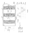
  • the multilevel modulator 110 forms four pulse-width modulated (PWM) driving signals 152 (labeled HM, LM, LP, HP) by combining the input analog signal 101 (+), 101 ( ⁇ ) and an internal, square carrier signal.
  • PWM pulse-width modulated
  • the formed PWM driving signals 152 are indicative of the input analog signal 101 (+), 101 ( ⁇ ), as illustrated in FIG. 1C .
  • the multilevel output stage 160 is driven by the four PWM driving signals 152 (HM, LM, LP, HP) and issues a first multilevel output signal 192 a to one output port (outP) of the amplifier system 100 and a second multilevel output signal 192 b to the other output port (outM) of the amplifier system.
  • each of the multilevel output signals 192 a , 192 b issued respectively to the output ports (outP, outM) has a dynamic range of [ ⁇ V DD , +2V DD ], that corresponds to a peak-to-peak swing of 3V DD , as shown in FIG. 1D .
  • differences between adjacent levels of each of the multilevel output signals 192 a , 192 b have a magnitude equal to V DD .
  • V DD V BAT for the double boosted implementation of the amplifier system 100
  • V DD V BST for the highly boosted implementation of the amplifier system 100
  • An amplified signal 192 provided by the multilevel output stage 160 to the load 105 coupled to the outputs (outP, outM), is a difference between the multilevel output signals 192 a , 192 b .
  • the amplified signal 192 provided to the load 105 is a multilevel replica of the input signal and has an amplitude of 3V DD , that corresponds to a peak-to-peak swing of 6V DD , as shown in FIG. 1D .
  • FIG. 2 shows aspects of a multilevel output stage 260 that can provide to a load a multilevel amplified signal V LOAD with an amplitude equal to an integer multiple of a power supply voltage V DD .
  • the multilevel output stage 260 can be used as the multilevel output stage 160 of the multilevel class-D amplifier 100 shown in FIGS. 1A-1B .
  • the multilevel output stage 260 can be formed on an IC chip, e.g., on the IC chip 103 shown in FIG. 1A .
  • the multilevel output stage 260 includes four output stage input ports (si 1 , si 3 , si 2 , si 4 ).
  • the output stage input ports (si 1 , si 3 , si 2 , si 4 ) are respectively coupled to modulator output ports of a multilevel modulator (e.g., the modulator output ports (mo 1 , mo 2 , mo 3 , mo 4 ) of the multilevel modulator 110 shown in FIG. 1A ) to receive respective driving PWM signals (LP, LM, HP, HM).
  • the multilevel output stage 260 includes four output stage boost ports (so 1 , so 3 , so 2 , so 4 ).
  • the multilevel output stage 260 includes a first pair of high-voltage (HV) switches (e.g., high-voltage power MOSFETs arranged in a cascoded structure) connected to each other at a first one (so 1 ) of the output stage boost ports (so 1 , so 3 , so 2 , so 4 ).
  • the first pair of HV switches is powered with a power supply voltage level V DD (relative to ground), and has a first control terminal coupled to a first one (si 1 ) of the output stage input ports (si 1 , si 3 , si 2 , si 4 ).
  • each of the HV switches of the first pair includes a gate terminal and the gate terminals are coupled with the first control terminal through logic circuitry.
  • a first PWM driving signal LP is applied to the first output stage input port (si 1 ), and the first output stage boost port (so 1 ) is coupled to one output port (outP) of the multilevel class-D amplifier where one of two terminals of a load is connected.
  • the multilevel output stage 260 includes a second pair of HV switches connected to each other at a second one (so 2 ) of the output stage boost ports (so 1 , so 3 , so 2 , so 4 ).
  • the second pair of HV switches also is powered with the power supply voltage level V DD , and has a second control terminal coupled to a second one (si 2 ) of the output stage input ports (si 1 , si 3 , si 2 , si 4 ).
  • each of the HV switches of the second pair includes a gate terminal, and the gate terminals are coupled with the second control terminal through logic circuitry.
  • an output bridge 270 is formed that includes the first pair of HV switches, the second pair of HV switches and the load.
  • the output bridge 270 provides to the load the amplified signal V LOAD .
  • the multilevel output stage 260 includes a first pair of low-voltage (LV) switches (e.g., low-voltage MOSFETs arranged in a cascoded complementary metal-oxide semiconductor (CMOS) structure) connected to each other at a third one (so 3 ) of the output stage boost ports (so 1 , so 3 , so 2 , so 4 ).
  • the first pair of LV switches also is powered with the power supply voltage level V DD , and has a third control terminal coupled to a third one (si 3 ) of the output stage input ports (si 1 , si 3 , si 2 , si 4 ).
  • each of the LV switches of the first pair includes a gate terminal and the gate terminals are coupled with the third control terminal through logic circuitry.
  • a third PWM driving signal HP is applied to the third output stage input port (si 3 ).
  • the multilevel output stage 260 includes a second pair of LV switches connected to each other at a fourth one (so 4 ) of the output stage boost ports (so 1 , so 3 , so 2 , so 4 ).
  • the second pair of LV switches also is powered with the power supply voltage level V DD , and has a fourth control terminal coupled to a fourth one (si 4 ) of the output stage input ports (si 1 , si 3 , si 2 , si 4 ).
  • each of the LV switches of the fourth pair includes a gate terminal, and the gate terminals are coupled with the fourth control terminal through logic circuitry.
  • the multilevel output stage 260 can be integrated in the amplifier system 100 , as is, i.e., without connecting one or two boost capacitors C BST1 , C BST2 to select pairs of the output stage boost ports (so 1 , so 3 , so 2 , so 4 ), and without connecting the boost inductor L BST to the boost stage 180 .
  • PWM driving signals LP, LM, HP, HM
  • respective output stage input ports si 1 , si 3 , si 2 , si 4 ).
  • FIG. 3B shows a graph 392 of an amplified signal V LOAD provided to the load at the output ports (outP, outM) of the output bridge 270 .
  • one or two boost capacitors C BST1 , C BST2 that are external to the multilevel output stage 260 , can be connected to select pairs of the output stage boost ports (so 1 , so 3 , so 2 , so 4 ), and the boost inductor L BST can be connected to the boost stage 180 , when the multilevel output stage 260 is integrated in the amplifier system 100 .
  • a boost capacitor C BST1 is coupled between the third output stage input port (si 3 ) and the first output stage input port (si 1 /outP) to form a boost bridge 272 a that includes the first pair of HV switches, the first pair of LV switches and the boost capacitor C BST1 .
  • FIG. 4A shows a graph 492 of a multilevel amplified signal V LOAD provided to the load by the output bridge 270 at the output ports (outP, outM).
  • the increase from V BAT to 2V BAT of the amplitude of the multilevel amplified signal V LOAD provided to the load at the output ports (outP, outM) of the output bridge 270 is caused by charging and discharging of the boost capacitor C BST1 of the boost bridge 272 a.
  • a first boost capacitor C BST1 is coupled between the third output stage input port (si 3 ) and the first output stage input port (si 1 /outP) to form a first boost bridge 272 a that includes the first pair of HV switches, the first pair of LV switches and the first boost capacitor C BST1 .
  • a second boost capacitor C BST2 is coupled between the fourth output stage input port (si 4 ) and the second output stage input port (si 2 /outM) to form a second boost bridge 272 b that includes the second pair of HV switches, the second pair of LV switches and the second boost capacitor C BST2 . This case is illustrated in FIG.
  • FIG. 5A shows a graph 592 of a multilevel amplified signal V LOAD provided to the load by the output bridge 270 at the output ports (outP, outM).
  • the increase from 2V BAT To 3V BAT of the amplitude of the multilevel amplified signal V LOAD provided to the load at the output ports (outP, outM) of the output bridge 270 is caused by charging and discharging of both the first boost capacitor C BST1 of the first boost bridge 272 a and the second boost capacitor C BST2 of the second boost bridge 272 b.
  • a first boost capacitor C BST1 is coupled between the third output stage input port (si 3 ) and the first output stage input port (si 1 /outP) to form a first boost bridge 272 a that includes the first pair of HV switches, the first pair of LV switches and the first boost capacitor C BST1 .
  • a second boost capacitor C BST2 is coupled between the fourth output stage input port (si 4 ) and the second output stage input port (si 2 /outM) to form a second boost bridge 272 b that includes the second pair of HV switches, the second pair of LV switches and the second boost capacitor C BST2 .
  • a boost inductor L BST is coupled between a battery that outputs a voltage level V BAT and an input of the boost stage 180 .
  • V L V BAT
  • PWM driving signals LP, LM, HP, HM
  • respective output stage input ports si 1 , si 3 , si 2 , si 4 ).
  • FIG. 6B shows a graph 692 of a multilevel amplified signal V LOAD provided to the load by the output bridge 270 at the output ports (outP, outM).
  • the increase from 2V BST to 3V BST of the amplitude of the multilevel amplified signal V LOAD provided to the load at the output ports (outP, outM) of the output bridge 270 is caused by charging and discharging of both the first boost capacitor C BST1 of the first boost bridge 272 a and the second boost capacitor C BST2 of the second boost bridge 272 b .
  • Connecting the boost inductor L BST to the boost stage 180 of the multilevel output stage 260 for the example illustrated in FIG. 6A , causes not only an increase of the amplitude of the amplified signal V LOAD from 11.1V to 15.5V compared to the example shown in FIG.
  • the amplitude 3V BST of the amplified signal V LOAD is independent from the state of charge of the battery.
  • the amplitude 3V BAT of the amplified signal V LOAD for the double boosted implementation of the multilevel output state 260 , illustrated in FIG. 5A can decrease along with the voltage level V BAT when the charge of the battery decreases.
  • FIG. 7 shows an example of a multilevel modulator 710 .
  • the multilevel modulator 710 can be used as the multilevel modulator 110 of the multilevel class-D amplifier 100 shown in FIGS. 1A-1B .
  • the multilevel modulator 710 can be formed on an IC chip, e.g., on the IC chip 103 shown in FIG. 1A .
  • the multilevel modulator 710 includes a pair of modulator input ports (mi 1 , mi 2 ).
  • the modulator input ports (mi 1 , mi 2 ) are respectively coupled to the input ports (inP, inM) of the amplifier system to receive a first instance 101 (+) and a second instance 101 ( ⁇ ) of an input analog signal.
  • the input analog signal is received by the multilevel modulator 710 as an input differential signal.
  • the multilevel modulator 110 includes four modulator output ports (mo 1 , mo 2 , mo 3 , mo 4 ). When used in the amplifier system 100 shown in FIG.
  • the modulator output ports (mo 1 , mo 2 , mo 3 , mo 4 ) are respectively coupled with the output stage input ports (si 1 , si 3 , si 2 , si 4 ) of the multilevel output stage 160 .
  • the multilevel modulator 710 forms four PWM signals (LP, LM, HP, HM) by combining the input differential signal 101 (+), 101 ( ⁇ ) with a square carrier signal 702 generated internally to the multilevel modulator.
  • the multilevel modulator 710 is arranged and configured as a fully differential integrator.
  • the fully differential integrator integrates only the carrier square wave 702 to obtain a triangular wave centered on a reference voltage V REF .
  • Comparison of the obtained triangular wave (centered on the reference voltage V REF ) to the reference voltage V REF results in a PWM signal with 50% duty cycle.
  • the fully differential integrator integrates a combination of the input differential signal and the carrier square wave 702 to obtain two triangular waves 742 (+), 742 ( ⁇ ) (having opposing signs), where the obtained triangular waves are indicative of the received input differential signal.
  • Comparators 770 a , 770 b of the multilevel modulator 710 perform comparisons of the obtained triangular waves 742 (+), 742 ( ⁇ ) to the reference voltage V REF , as shown in FIG. 8 , in portion 842 of graph 800 .
  • the multilevel modulator 710 generates, based on results of the comparisons, respective PWM signals (LP, LM) having differential (opposite in time) duty cycles, as shown in FIG. 8 , in portion 852 of graph 800 .
  • the generated PWM signals (LP, LM) are output at respective first and second modulator output ports (mo 1 , mo 2 ) of the multilevel modulator 710 .
  • the PWM signals are used to respectively drive the first pair of HV switches and the second pair of HV switches of the multilevel output stage, when the multilevel output signals 192 a , 192 b —respectively issued by the first pair of HV switches and the second pair of HV switches—swing from ground to V DD , where V DD can be V BAT or V BST , as described above in connection with FIGS. 5A and 6A .
  • the multilevel modulator 710 generates, based on results of the comparisons, respective PWM signals (HP, HM) having differential (opposite in time) duty cycles, as shown in FIG. 8 , in portion 854 of graph 800 .
  • the generated PWM signals (HP, HM) are output at respective third and fourth modulator output ports (mo 3 , mo 4 ) of the multilevel modulator 710 .
  • the PWM signals (HP, HM) are used to respectively drive the first pair of LV switches and the second pair of LV switches of the multilevel output stage, such that if the multilevel output signals 192 a , 192 b —respectively issued by the first pair of HV switches and the second pair of HV switches—swing (i) from V DD to 2V DD , then the gates of the cascoded MOSFETs of each of the first pair of LV switches and the second pair of LV switches are connected to V DD , or (ii) from ground to ⁇ V DD , then the gates of the cascoded MOSFETs of each of the first pair of LV switches and the second pair of LV switches are connected to ground.
  • each of the first pair of HV switches and the second pair of HV switches can safely issue respective multilevel output signals 192 a , 192 b that swing between +2V DD and ⁇ V DD , as shown above in graphs 192 a , 192 b , without causing damage to the power MOSFETs included therein.
  • Charge-pump circuitry includes four switches (e.g., MOSFETs) in a bridge configuration with the fly capacitor C Fly , and the switches of the charge-pump circuitry are always ON, hence, a contribution of the charge-pump circuitry to R OUT,CP is a resistance 4R ON .
  • R ON is the series resistance of a single MOSFET in its ON state.
  • the contribution of the output bridge to R OUT,CP is a resistance 2R ON .
  • the contribution to the output resistance R OUT of the multilevel output stage 260 (as shown, e.g., in FIG. 2 or FIG. 6A ) varies based on an amplitude of the amplified signal V LOAD output at the output ports (outP, outM).
  • V LOAD the amplified signal amplitude
  • the output resistance of the multilevel output stage 260 over all amp

Abstract

Implementations of a class-D amplifier can be used to amplify an input analog signal and provide to a load a multilevel amplified signal having an amplitude larger than a voltage level of a power source used by the class-D amplifier.

Description

CROSS-REFERENCE TO RELATED APPLICATIONS
This disclosure claims priority to U.S. Provisional Application Ser. No. 62/120,172, filed Feb. 24, 2015, the disclosure of which is incorporated herein by reference in its entirety.
BACKGROUND
The present disclosure is generally related to class-D amplifiers, and more specifically to multilevel class-D amplifiers.
A class-D amplifier, also known as a switching amplifier, includes amplifying devices (e.g., field-effect transistors (FETs), metal-oxide FETs (MOSFETs), power MOSFETs) that are implemented as electronic switches, instead of as linear gain devices, as in linear amplifiers. A class-D amplifier includes an input stage that uses, e.g., pulse-width modulation (PWM), to convert an input analog signal (to be amplified by the class-D amplifier) to a train of constant amplitude pulses having a variable duty cycle that is proportional to instantaneous values of the input analog signal. The train of pulses, also referred to as a PWM signal, is indicative of the input signal. The class-D amplifier further includes an output stage that uses two pairs of high-voltage switches (e.g., power MOSFETs) which are driven by respective instances of the PWM signal and, when a load is coupled to output ports of the output stage, are arranged to form an output bridge. In this manner, the output stage delivers a constantly changing voltage into the coupled load as an amplified signal, which is an amplified replica of the PWM signal provided by the input stage. A low-pass filter can remove high-frequency switching components of the amplified signal to recover information carried by the input analog signal, where the recovered information is to be used by the load. Note that, although the class-D amplifier uses a source of DC power, e.g., a battery that outputs a voltage level VBAT (e.g., VBAT=3.7V), the amplification process itself operates by switching.
Moreover, boosting technologies can be implemented in conjunction with the output stage to increase a level of the foregoing amplified signal above VBAT. FIG. 9A shows an output stage of a class-D amplifier implemented in a conventional charge-pump configuration. Here, the output stage is driven by two PWM signals (LP and LM) indicative of an input analog signal, and uses a charge-pump circuit, powered by a voltage level VBAT, in conjunction with a fly capacitor CFly and a tank capacitor CTank. In this manner, the output bridge of the output stage is powered by a larger voltage level 2VBAT output by the charge-pump circuit. Hence, an amplified signal VLoad, provided to the load by the output stage implemented in the charge-pump configuration, is a train of pulses having constant amplitude 2VBAT=7.4V>VBAT, as shown in FIG. 9B. FIG. 10A shows an output stage of a class-D amplifier implemented in a conventional DC-DC boosted configuration. Here, the output stage also is driven by two PWM signals (LP and LM) indicative of an input analog signal, but uses a DC-DC boost converter, powered by a voltage level VBAT through a boost inductor LBST. In this manner, the output bridge of the output stage is powered by a larger voltage level VBST output by the DC-DC boost converter, where VBST>VBAT (because, e.g., VBST=5.5V). Hence, an amplified signal VLoad provided to the load, by the output stage implemented in the DC-DC boosted configuration, is a train of pulses having constant amplitude VBST, as shown in FIG. 10B.
A conventional combination of the charge-pump configuration and the DC-DC boosted configuration of the class-D amplifier can be implemented, in which a DC-DC boost converter powered by VBAT through a boost inductor LBST powers the charge-pump circuitry and causes the latter to output a voltage 2VBAT=11V. Here, an amplified signal VLoad provided to the load, by the output stage implemented as a combination of charge-pump configuration and DC-DC boosted configuration, is a train of pulses having constant amplitude 2VBST. Note, however, that the amplified signal VLoad (e.g., illustrated either in FIG. 9B or FIG. 10B) provided to the load by the output stage, in either of the conventional configurations shown in FIG. 9A or FIG. 10A or in the noted conventional combination thereof, is always a single-level amplified signal.
SUMMARY
In this specification, implementations of a class-D amplifier are described that can be used to amplify an input analog signal and provide to a load a multilevel amplified signal having an amplitude larger than a voltage level of a power source used by the class-D amplifier.
One aspect of the disclosure can be implemented as an amplifier system for amplifying an input signal that varies over time. The amplifier system includes a multilevel output stage powered with a voltage having a predetermined voltage level relative to ground; a multilevel modulator configured to form a plurality of pulse-width modulated (PWM) driving signals based on i) the input signal and ii) a square carrier signal. Additionally, the multilevel modulator is further configured to drive the multilevel output stage with the plurality of PWM driving signals. The amplifier system further includes a pair of output ports coupled with the multilevel output stage; and a boost capacitor coupled with a first output port of the pair of output ports. The multilevel output stage is configured to output, at the pair of output ports, when driven with the plurality of PWM driving signals, an output signal having a plurality of levels. Here, differences between adjacent levels of the output signal have a magnitude equal to the predetermined voltage level, an amplitude of the output signal is a non-unity integer multiple of the predetermined voltage level, and the output signal varies over time between its multiple levels in accordance with the input signal.
Implementations can include one or more of the following features. In some implementations, the multilevel output stage can include four high-voltage (HV) switches, which form, when a load is coupled between the pair of output ports, an output bridge that includes the four HV switches and the load; and a boost bridge that includes a pair of the HV switches, a pair of low-voltage (LV) switches, and the boost capacitor. Here, the boost bridge is driven by a pair of PWM driving signals of the plurality of PWM driving signals. In some of these cases, the amplitude of the output signal can be twice the predetermined voltage level.
In some of the foregoing implementations, the multilevel output stage further can include a second boost capacitor coupled with a second output port of the pair of output ports; and a second boost bridge that includes a second pair of the HV switches, a second pair of LV switches, and the second boost capacitor. Here, the second boost bridge is driven by a second pair of PWM driving signals of the plurality of PWM driving signals. In some of these cases, the amplitude of the output signal can be three times the predetermined voltage level. In some cases, the amplifier system can include a power supply that provides the predetermined voltage level to the multilevel output stage. In other cases, when the multilevel output stage further includes a boost stage, the amplifier system can include a power supply that powers the boost stage through a boost inductor with a power supply voltage level smaller than the power supply voltage level, and causes the boost stage to provide the predetermined voltage level to the first and second boost bridges.
In some implementations, the multilevel modulator can include a fully differential integrator. Here, the multilevel modulator can include a differential input to receive the input signal. Also here, the multilevel modulator can include four outputs through which respective four PWM driving signals are delivered to the multilevel output stage.
Another aspect of the disclosure can be implemented as an integrated circuit chip including amplifier circuitry. The amplifier circuitry includes (I) a multilevel modulator including (i) two modulator input ports, and (ii) four modulator output ports; and (II) a multilevel output stage including (i) four output stage input ports respectively coupled with the four modulator output ports, (ii) four output stage boost ports, (iii) a first pair of high-voltage (HV) switches connected to each other at a first one of the output stage boost ports, the first pair of HV switches having a first control terminal coupled to a first one of the output stage input ports, (iv) a second pair of HV switches connected to each other at a second one of the output stage boost ports, the second pair of HV switches having a second control terminal coupled to a second one of the output stage input ports, (v) a first pair of low-voltage (LV) switches connected to each other at a third one of the output stage boost ports, the first pair of LV switches having a third control terminal coupled to a third one of the output stage input ports, and (vi) a second pair of LV switches connected to each other at a fourth one of the output stage boost ports, the second pair of LV switches having a fourth control terminal coupled to a fourth one of the output stage input ports.
Implementations can include one or more of the following features. In some implementations, an amplification system can include the foregoing integrated circuit chip including amplifier circuitry. In addition, the amplification system further can include two amplifier input ports respectively coupled with the modulator input ports; and two amplifier output ports respectively coupled with the first output stage boost port and the second output stage boost port. Here, during operation of the amplifier system, a load coupled between the two amplifier output ports causes formation of an output bridge that includes the first pair of HV switches, the second pair of HV switches and the load.
In some implementations, the amplifier system can include a boost capacitor having two terminals, one of the two terminals being coupled to the first output stage boost port, and another of the two terminals being coupled to the third output stage boost port, thereby forming a boost bridge that includes the first pair of HV switches, the first pair of LV switches and the boost capacitor. Here, the amplifier system can further include a second boost capacitor having two terminals, one of the two terminals of the second boost capacitor being coupled to the second output stage boost port and at the other one of the terminals of the second boost capacitor being coupled to the fourth output stage boost port, thereby forming a second boost bridge that includes the second pair of HV switches, the second pair of LV switches and the second boost capacitor. For some cases, the amplifier system can further include a power supply to power the multilevel output stage with a predetermined voltage level. In other cases, when the multilevel output stage includes a boost stage including a boost stage input and a boost stage output, the amplification system can further include a boost inductor coupled with the boost stage input; and a power supply to power the boost stage through the boost inductor with a power supply voltage level. In the latter cases, the boost stage can power the multilevel output stage with a predetermined voltage level that is boosted relative to the power supply voltage level.
In some implementations, the multilevel modulator can include a fully differential integrator. Here, the multilevel modulator is configured perform, during operation of the integrated circuit chip including amplifier circuitry, operations including: (I) receive an input signal through the modulator input ports, (II) form four pulse-width modulated (PWM) drive signals based on (i) the input signal and (ii) a square carrier signal, and (III) provide the four PWM drive signals, through respective modulator output ports to respective output stage input ports, to drive the output stage.
The disclosed technologies can result in one or more of the following potential advantages. An input stage and an output stage of the disclosed class-D amplifier, the latter stage including a boost stage to be activated through a boost inductor, can be formed on an integrated circuit (IC) chip, and the IC chip can be used in an amplification system configurable in accordance with specific use cases. For example, the IC chip can be used, as is (i.e., without connecting one or two boost capacitors to select pairs of outputs of the output stage, and without connecting the boost inductor to the boost stage), in an amplification system configured to amplify audio signals in a low end consumer electronics device, e.g., an inexpensive smartphone, to provide to its speaker (or to earphones plugged to its audio jack) amplified signals with an amplitude up to a voltage level (e.g., VBAT=3.7V) of a power source used by the IC chip. In this case, the power delivered into an 8Ω load is about 0.5 W. As another example, one or two boost capacitors can be connected to select one or two pairs of output ports of the IC chip (but without connecting the boost inductor to the boost stage) as part of the amplification system configured to amplify audio signals in a mid-level consumer electronics device, e.g., a mid-range priced smartphone, to provide to its speaker (or to earphones plugged to its audio jack) amplified signals with an amplitude up to respectively twice or three times the voltage level (e.g., 2VBAT=7.4V or 3VBAT=11.1V) of a power source used by the IC chip. In these cases, the power delivered into an 8Ω load is about 2 W or 4 W, respectively. As yet another example, one or two boost capacitors can be connected to select pairs of output ports of the IC chip, and the boost inductor can be connected to the boost stage as part of the amplification system configured to amplify audio signals in a high end consumer electronics device, e.g., an expensive smartphone, to provide to its speaker (or to earphones plugged to its audio jack) amplified signals with an amplitude up to three times the voltage level (e.g., 3VBST=16.5V) output by the boost stage. In this case, the power delivered into an 8Ω load is about 8 W. This kind of use case configurability of the disclosed class-D amplifier is possible neither in the charge-pump implementation of the class-D amplifier shown in FIG. 9A, where the fly capacitor CFly and the tank capacitor CTank must be part of the amplifier system, nor in the DC-DC boosted configuration of the class-D amplifier shown in FIG. 10A, where the boost inductor LBST must be part of the amplifier system.
Further, some of the disclosed implementations of the class-D amplifier that do not require for a boost inductor to be part of the disclosed amplifier system can output an amplified signal having an amplitude 3VBAT=11.1V that is comparable to the amplitude 2VBST=11V of an amplified signal output by the above-noted conventional combination of the configurations shown in FIG. 9A or FIG. 10A, which often requires a boost inductor LBST to be part of the latter conventional amplifier system. In this manner, the disclosed amplifier system can be less voluminous than, while delivering the same performance as, the foregoing conventional amplifier system.
Furthermore, an area of silicon required for the smaller, LV switches included in the boost stage of the IC chip of the disclosed class-D amplifier is smaller than an area of silicon required for the larger, HV switches included in the DC-DC boost convertor of the IC chip of the conventional class-D amplifier illustrated in FIG. 10A. Thus, the IC chip of the disclosed class-D amplifier is less voluminous and consumes less power than the IC chip of the conventional class-D amplifier illustrated in FIG. 10A.
In addition, the multilevel output stage of the disclosed amplifier system has smaller output resistance ROUT than the output resistance ROUT,CP of the single-level output stage of the conventional charge-pump implementation of the class-D amplifier shown in FIG. 9A, and thus the disclosed amplifier system can transfer power more efficiently to a load than the noted conventional amplifier system.
Another benefit of using a multilevel output stage for the disclosed amplifier system is that the amplitude of the amplified signal output by the disclosed class-D amplifier varies in steps equal to a voltage level (e.g., VBAT) of a power source used by the IC chip. In contrast, the conventional charge-pump implementation of the class-D amplifier illustrated in FIG. 9A uses a single-level output stage, and thus, the amplitude of the amplified signal output by the conventional charge-pump implementation of the class-D amplifier varies in steps equal to twice the voltage level VBAT (as shown in FIG. 9B). The small changes VBAT (e.g., 3.7V) in amplitude of the amplified signal output by the disclosed amplifier system cause smaller electromagnetic interference (EMI) noise than the EMI noise caused by large changes 2VBAT (e.g., 7.4V) in amplitude of the amplified signal output by conventional charge-pump amplifier systems.
Details of one or more implementations of the disclosed technologies are set forth in the accompanying drawings and the description below. Other features, aspects, descriptions and potential advantages will become apparent from the description, the drawings and the claims.
BRIEF DESCRIPTION OF THE DRAWINGS
FIGS. 1A-1D show aspects of a multilevel class D amplifier that includes a multilevel modulator and a multilevel output stage.
FIG. 2 shows aspects of a multilevel output stage that provides a multilevel output signal with an amplitude equal to a non-unity integer multiple of a power supply voltage.
FIGS. 3A-3B show aspects of a multilevel output stage that provides an output signal with an amplitude equal to a power supply voltage.
FIGS. 4A-4B show aspects of a multilevel output stage that provides a multilevel output signal with an amplitude equal to twice a power supply voltage.
FIGS. 5A-5B show aspects of a multilevel output stage that provides a multilevel output signal with an amplitude equal to three times a power supply voltage.
FIGS. 6A-6B show aspects of a multilevel output stage that provides a multilevel output signal with an amplitude equal to three times a boosted power supply voltage.
FIG. 7 shows an example of a multilevel modulator.
FIG. 8 shows aspects of signals formed inside, and aspects of pulse-width modulated (PWM) driving signals output by, the multilevel modulator from FIG. 7.
FIGS. 9A-9B show aspects of a conventional charge-pump implementation of an output stage of a class D amplifier.
FIGS. 10A-10B show aspects of a conventional DC-DC boosted implementation of an output stage of a class D amplifier.
Certain illustrative aspects of the systems, apparatuses, and methods according to the disclosed technologies are described herein in connection with the following description and the accompanying figures. These aspects are, however, indicative of but a few of the various ways in which the principles of the disclosed technologies may be employed and the disclosed technologies are intended to include all such aspects and their equivalents. Other advantages and novel features of the disclosed technologies may become apparent from the following detailed description when considered in conjunction with the figures.
DETAILED DESCRIPTION
FIGS. 1A-1D show aspects of a multilevel class D amplifier 100, also referred to as an amplifier system or amplification system, that includes a multilevel modulator 110 and a multilevel output stage 160. FIG. 1A shows an example of an implementation of the amplifier system 100 in which the multilevel modulator 110 and the multilevel output stage 160 are part of the same IC chip 103. In other implementations, the multilevel modulator 110 is part of a first IC chip and the multilevel output stage 160 is part of a second, different IC chip. Further, the amplifier system 100 includes a pair of input ports (inP, inM) to receive an input analog signal, when an analog signal source 102 is coupled to the input ports. Note that the input analog signal can be an audio signal having frequency components in the audio frequency range [200 Hz, 20 kHz], or can be an analog signal having frequency components in other frequency ranges (e.g., lower than, overlapping or higher than the audio frequency range). Furthermore, the amplifier system 100 includes a pair of output ports (outP, outM) to provide an amplified signal, when a load 105 is coupled to the output ports. Here, the amplified signal is an amplified replica of the input analog signal received from the signal source 102.
The multilevel modulator 110 includes a pair of modulator input ports (mi1, mi2) that are respectively coupled to the input ports (inP, inM) of the amplifier system 100. Additionally, the multilevel modulator 110 includes four modulator output ports (mo1, mo2, mo3, mo4). The multilevel output stage 160 includes four output stage input ports (si1, si3, si2, si4) respectively coupled to the four modulator output ports (mo1, mo2, mo3, mo4). Also, the multilevel output stage 160 includes four output stage boost ports (so1, so3, so2, so4). Here, a first pair (so1, so2) of the output stage boost ports (so1, so3, so2, so4) is coupled to the output ports (outP, outM) of the amplifier system 100.
In some implementations, a terminal of a power supply associated with the amplifier system 100 that is biased with a voltage level VBAT is coupled directly with the multilevel output stage 160 through a power connector. In other implementations, the terminal of the power supply that is biased with the voltage lever VBAT is coupled with the multilevel output stage 160 through a boost inductor LBST of the amplifier system 100. Here, the power supply can be a battery and a value of the voltage level can be VBAT=3.7V. It should be noted that the mechanisms described herein apply equally to other types of power supplies and/or other voltage levels.
In addition, the amplifier system 100 can include a boost capacitor CBST1 having two terminals, where one of the two terminals is coupled to the first output stage boost port so1—that also is coupled to the first output port outP, and another of the two terminals is coupled to the third output stage boost port so3. In this boosted implementation of the amplifier system 100, the predetermined voltage level VBAT is provided by the power supply directly to the multilevel output stage 160, as described below in connection with FIGS. 4A-4B. Note that the boost capacitor CBST1 and the power supply can be connected to the multilevel output stage 160 in the foregoing manner during fabrication of the amplifier system 100, e.g., to satisfy specifications of a low-to-mid-priced consumer electronics device in which this boosted amplifier system will be integrated.
Further, the amplifier system 100 can include a second boost capacitor CBST2 in addition to the boost capacitor CBST1. The second boost capacitor CBST2 also has two terminals, where one of the two terminals is coupled to the second output stage boost port so2, which is coupled to the second output port outM, and another of the two terminals is coupled to the fourth output stage boost port so4. In this double-boosted implementation of the amplifier system 100, the predetermined voltage level VBAT is provided by the power supply directly to the multilevel output stage 160, as described below in connection with FIGS. 5A-5B. Note that the boost capacitor CBST1, the second boost capacitor CBST2 and the power supply can be connected to the multilevel output stage 160 in the foregoing manner during fabrication of the amplifier system 100, e.g., to satisfy specifications of a mid-to-high-priced consumer electronics device in which this double-boosted amplifier system will be integrated.
Moreover, a highly boosted implementation of the amplifier system 100 once again includes the boost capacitor CBST1 coupled between the first output stage boost port so1 and the third output stage boost port so3 and the second boost capacitor CBST2 coupled between the second output stage boost port so2 and the fourth output stage boost port so4. However, in the highly boosted implementation of the amplifier system 100, the predetermined voltage level VBAT is provided by the power supply to the multilevel output stage 160 through the boost inductor LBST, as described below in connection with FIGS. 6A-6B. Note that the boost capacitor CBST1, the second boost capacitor CBST2, the boost inductor LBST and the power supply can be connected to the multilevel output stage 160 in the foregoing manner during fabrication of the amplifier system 100, e.g., to satisfy specifications of a high-priced consumer electronics device in which this boosted amplifier system will be integrated.
FIG. 1B shows an implementation of the amplifier system 100 in which the boost capacitor CBST1 is connected to one output port (outP) of the amplifier system and second the boost capacitor CBST2 is connected to the other output port (outM) of the amplifier system as described above for the double-boosted implementation or the highly boosted implementation of the amplifier system. In the example illustrated in FIG. 1B, a first instance 101(+) and a second instance 101(−) of the input analog signal is received by the amplifier system 100 through the input ports (inP, inM). Here, the input analog signal 101(+), 101(−) is an audio signal, and the load 105 coupled to the output ports (outP, outM) of the amplifier system 100 is a speaker.
The multilevel modulator 110 forms four pulse-width modulated (PWM) driving signals 152 (labeled HM, LM, LP, HP) by combining the input analog signal 101(+), 101(−) and an internal, square carrier signal. The formed PWM driving signals 152 (HM, LM, LP, HP) are indicative of the input analog signal 101(+), 101(−), as illustrated in FIG. 1C.
Referring again to FIG. 1B, the multilevel output stage 160 is driven by the four PWM driving signals 152 (HM, LM, LP, HP) and issues a first multilevel output signal 192 a to one output port (outP) of the amplifier system 100 and a second multilevel output signal 192 b to the other output port (outM) of the amplifier system. In this implementation, each of the multilevel output signals 192 a, 192 b issued respectively to the output ports (outP, outM) has a dynamic range of [−VDD, +2VDD], that corresponds to a peak-to-peak swing of 3VDD, as shown in FIG. 1D. Moreover, differences between adjacent levels of each of the multilevel output signals 192 a, 192 b have a magnitude equal to VDD. Note that VDD =VBAT for the double boosted implementation of the amplifier system 100, when the power supply provides the predetermined voltage level VBAT directly to the multilevel output stage 160, and VDD=VBST for the highly boosted implementation of the amplifier system 100, when the power supply provides the predetermined voltage level VBAT to the multilevel output stage through the boost inductor LBST. For example, a value of the boosted voltage level is VBST=5.5V.
An amplified signal 192, provided by the multilevel output stage 160 to the load 105 coupled to the outputs (outP, outM), is a difference between the multilevel output signals 192 a, 192 b. In this manner, the amplified signal 192 provided to the load 105 is a multilevel replica of the input signal and has an amplitude of 3VDD, that corresponds to a peak-to-peak swing of 6VDD, as shown in FIG. 1D. As in the case of the multilevel output signals 192 a, 192 b, differences between adjacent levels of the amplified signal 192 have a magnitude equal to VDD (where VDD=VBAT or VDD=VBST).
FIG. 2 shows aspects of a multilevel output stage 260 that can provide to a load a multilevel amplified signal VLOAD with an amplitude equal to an integer multiple of a power supply voltage VDD. The multilevel output stage 260 can be used as the multilevel output stage 160 of the multilevel class-D amplifier 100 shown in FIGS. 1A-1B. Note that the multilevel output stage 260 can be formed on an IC chip, e.g., on the IC chip 103 shown in FIG. 1A.
The multilevel output stage 260 includes four output stage input ports (si1, si3, si2, si4). When integrated in a multilevel class-D amplifier (like the one shown in FIGS. 1A-1B), the output stage input ports (si1, si3, si2, si4) are respectively coupled to modulator output ports of a multilevel modulator (e.g., the modulator output ports (mo1, mo2, mo3, mo4) of the multilevel modulator 110 shown in FIG. 1A) to receive respective driving PWM signals (LP, LM, HP, HM). Further, the multilevel output stage 260 includes four output stage boost ports (so1, so3, so2, so4).
The multilevel output stage 260 includes a first pair of high-voltage (HV) switches (e.g., high-voltage power MOSFETs arranged in a cascoded structure) connected to each other at a first one (so1) of the output stage boost ports (so1, so3, so2, so4). The first pair of HV switches is powered with a power supply voltage level VDD (relative to ground), and has a first control terminal coupled to a first one (si1) of the output stage input ports (si1, si3, si2, si4). Note that each of the HV switches of the first pair includes a gate terminal and the gate terminals are coupled with the first control terminal through logic circuitry. When the multilevel output stage 260 is used in the multilevel class-D amplifier 100, a first PWM driving signal LP is applied to the first output stage input port (si1), and the first output stage boost port (so1) is coupled to one output port (outP) of the multilevel class-D amplifier where one of two terminals of a load is connected. Additionally, the multilevel output stage 260 includes a second pair of HV switches connected to each other at a second one (so2) of the output stage boost ports (so1, so3, so2, so4). The second pair of HV switches also is powered with the power supply voltage level VDD, and has a second control terminal coupled to a second one (si2) of the output stage input ports (si1, si3, si2, si4). Note that each of the HV switches of the second pair includes a gate terminal, and the gate terminals are coupled with the second control terminal through logic circuitry. When the multilevel output stage 260 is used in the multilevel class-D amplifier 100, a second PWM driving signal LM is applied to the second output stage input port (si2), and the second output stage boost port (so1) is coupled to the other output port (outM) of the multilevel class-D amplifier where the other one of the two terminals of the load is connected. In this manner, when the load is connected to the output ports (outP, outM), an output bridge 270 is formed that includes the first pair of HV switches, the second pair of HV switches and the load. Here, the output bridge 270 provides to the load the amplified signal VLOAD.
Further, the multilevel output stage 260 includes a first pair of low-voltage (LV) switches (e.g., low-voltage MOSFETs arranged in a cascoded complementary metal-oxide semiconductor (CMOS) structure) connected to each other at a third one (so3) of the output stage boost ports (so1, so3, so2, so4). The first pair of LV switches also is powered with the power supply voltage level VDD, and has a third control terminal coupled to a third one (si3) of the output stage input ports (si1, si3, si2, si4). Note that each of the LV switches of the first pair includes a gate terminal and the gate terminals are coupled with the third control terminal through logic circuitry. When the multilevel output stage 260 is used in the multilevel class-D amplifier 100, a third PWM driving signal HP is applied to the third output stage input port (si3). Furthermore, the multilevel output stage 260 includes a second pair of LV switches connected to each other at a fourth one (so4) of the output stage boost ports (so1, so3, so2, so4). The second pair of LV switches also is powered with the power supply voltage level VDD, and has a fourth control terminal coupled to a fourth one (si4) of the output stage input ports (si1, si3, si2, si4). Note that each of the LV switches of the fourth pair includes a gate terminal, and the gate terminals are coupled with the fourth control terminal through logic circuitry. When the multilevel output stage 260 is used in the multilevel class-D amplifier 100, a fourth PWM driving signal HM is applied to the fourth output stage input port (si4).
Moreover, the multilevel output stage 260 includes a boost stage 180. If the boost stage 180 is powered with a voltage level VL through a boost inductor LBST, which is external to the multilevel output stage, then the boost stage outputs the power supply voltage level VDD =VBST (relative to ground). For example, a battery is used to provide the voltage level VL, such that VL=VBAT<VBST. Else, if the boost stage 180 is not powered, i.e., a boost inductor LBST is not connected between the battery and the boost stage 180, then the battery is connected directly to the multilevel output stage 260 (not via the boost inductor LBST) and provides the power supply voltage level VDD =VBAT (relative to ground).
The multilevel output stage 260 can be integrated in the amplifier system 100, as is, i.e., without connecting one or two boost capacitors CBST1, CBST2 to select pairs of the output stage boost ports (so1, so3, so2, so4), and without connecting the boost inductor LBST to the boost stage 180. This case is illustrated in FIG. 3A, where LBST=N/A, VL=N/A, CBST1=N/A, CBST2=N/A and the power supply voltage level is VDD=VBAT. Here, PWM driving signals (LP, LM, HP, HM) are applied to respective output stage input ports (si1, si3, si2, si4). FIG. 3B shows a graph 392 of an amplified signal VLOAD provided to the load at the output ports (outP, outM) of the output bridge 270. In this case, an amplitude of the amplified signal VLOAD is equal to the power supply voltage level VBAT, e.g., amplitude(VLOAD)=3.7V.
Referring again to FIG. 2, one or two boost capacitors CBST1, CBST2, that are external to the multilevel output stage 260, can be connected to select pairs of the output stage boost ports (so1, so3, so2, so4), and the boost inductor LBST can be connected to the boost stage 180, when the multilevel output stage 260 is integrated in the amplifier system 100. In a first example, a boost capacitor CBST1 is coupled between the third output stage input port (si3) and the first output stage input port (si1/outP) to form a boost bridge 272 a that includes the first pair of HV switches, the first pair of LV switches and the boost capacitor CBST1. This case is illustrated in FIG. 4A, where LBST=N/A, VL=N/A, CBST2=N/A and the power supply voltage level is VDD=VBAT. Here, PWM driving signals (LP, LM, HP, HM) are applied to respective output stage input ports (si1, si3, si2, si4), and a value of 10 μF can be chosen for the boost capacitor CBST1 of the boost bridge 272 a, for instance. FIG. 4B shows a graph 492 of a multilevel amplified signal VLOAD provided to the load by the output bridge 270 at the output ports (outP, outM). In this case, an amplitude of the amplified signal VLOAD is equal to twice the power supply voltage level 2VBAT, e.g., amplitude(VLOAD)=3.7+3.7=7.4V, while differences between adjacent levels of the multilevel amplified signal VLOAD have a magnitude equal to the power supply voltage level VBAT. The increase from VBAT to 2VBAT of the amplitude of the multilevel amplified signal VLOAD provided to the load at the output ports (outP, outM) of the output bridge 270 is caused by charging and discharging of the boost capacitor CBST1 of the boost bridge 272 a.
Referring again to FIG. 2, as a second example, a first boost capacitor CBST1 is coupled between the third output stage input port (si3) and the first output stage input port (si1/outP) to form a first boost bridge 272 a that includes the first pair of HV switches, the first pair of LV switches and the first boost capacitor CBST1. And a second boost capacitor CBST2 is coupled between the fourth output stage input port (si4) and the second output stage input port (si2/outM) to form a second boost bridge 272 b that includes the second pair of HV switches, the second pair of LV switches and the second boost capacitor CBST2. This case is illustrated in FIG. 5A, where LBST=N/A, VL=N/A and the power supply voltage level is VDD=VBAT. Here, PWM driving signals (LP, LM, HP, HM) are applied to respective output stage input ports (si1, si3, si2, si4), and a value of 10 μF can be chosen for both the first boost capacitor CBST1 of the first boost bridge 272 a and the second boost capacitor CBST2 of the second boost bridge 272 b, for instance. FIG. 5B shows a graph 592 of a multilevel amplified signal VLOAD provided to the load by the output bridge 270 at the output ports (outP, outM). In this case, an amplitude of the amplified signal VLOAD is equal to three times the power supply voltage level 3VBAT, e.g., amplitude(VLoAD)=3.7+3.7+3.7=11.1V, while differences between adjacent levels of the multilevel amplified signal VLOAD have a magnitude equal to the power supply voltage level VBAT. The increase from 2VBAT To 3VBAT of the amplitude of the multilevel amplified signal VLOAD provided to the load at the output ports (outP, outM) of the output bridge 270 is caused by charging and discharging of both the first boost capacitor CBST1 of the first boost bridge 272 a and the second boost capacitor CBST2 of the second boost bridge 272 b.
Referring again to FIG. 2, as a third example, a first boost capacitor CBST1 is coupled between the third output stage input port (si3) and the first output stage input port (si1/outP) to form a first boost bridge 272 a that includes the first pair of HV switches, the first pair of LV switches and the first boost capacitor CBST1. Further, a second boost capacitor CBST2 is coupled between the fourth output stage input port (si4) and the second output stage input port (si2/outM) to form a second boost bridge 272 b that includes the second pair of HV switches, the second pair of LV switches and the second boost capacitor CBST2. Furthermore, a boost inductor LBST is coupled between a battery that outputs a voltage level VBAT and an input of the boost stage 180. This case is illustrated in FIG. 6A, where the voltage level VL used to power the boost stage 180 through the boost inductor LBST is VL=VBAT, which causes for the power supply voltage level VDD to be equal to a boosted voltage level VBST output by the boost stage 180: VDD=VBST. Here, PWM driving signals (LP, LM, HP, HM) are applied to respective output stage input ports (si1, si3, si2, si4). Moreover, a value of 10 μF can be chosen for both the first boost capacitor CBST1 of the first boost bridge 272 a and the second boost capacitor CBST2 of the second boost bridge 272 b, and a value of 2 μH can be chosen for the boost inductance LBST, for instance. FIG. 6B shows a graph 692 of a multilevel amplified signal VLOAD provided to the load by the output bridge 270 at the output ports (outP, outM). In this case, an amplitude of the amplified signal VLOAD is equal to three times the power supply voltage level 3VBST, e.g., amplitude(VLOAD)=5.5+5.5+5.5=16.5V, while differences between adjacent levels of the multilevel amplified signal VLOAD have a magnitude equal to the power supply voltage level VBST. Once again, the increase from 2VBST to 3VBST of the amplitude of the multilevel amplified signal VLOAD provided to the load at the output ports (outP, outM) of the output bridge 270 is caused by charging and discharging of both the first boost capacitor CBST1 of the first boost bridge 272 a and the second boost capacitor CBST2 of the second boost bridge 272 b. Connecting the boost inductor LBST to the boost stage 180 of the multilevel output stage 260, for the example illustrated in FIG. 6A, causes not only an increase of the amplitude of the amplified signal VLOAD from 11.1V to 15.5V compared to the example shown in FIG. 5A, but also ensures that the amplitude 3VBST of the amplified signal VLOAD is independent from the state of charge of the battery. In contrast, the amplitude 3VBAT of the amplified signal VLOAD for the double boosted implementation of the multilevel output state 260, illustrated in FIG. 5A, can decrease along with the voltage level VBAT when the charge of the battery decreases.
FIG. 7 shows an example of a multilevel modulator 710. The multilevel modulator 710 can be used as the multilevel modulator 110 of the multilevel class-D amplifier 100 shown in FIGS. 1A-1B. Note that the multilevel modulator 710 can be formed on an IC chip, e.g., on the IC chip 103 shown in FIG. 1A.
The multilevel modulator 710 includes a pair of modulator input ports (mi1, mi2). When used in the amplifier system 100 shown in FIG. 1A, the modulator input ports (mi1, mi2) are respectively coupled to the input ports (inP, inM) of the amplifier system to receive a first instance 101(+) and a second instance 101(−) of an input analog signal. Note that in the configurations shown in FIGS. 1A-1B and 7, the input analog signal is received by the multilevel modulator 710 as an input differential signal. Additionally, the multilevel modulator 110 includes four modulator output ports (mo1, mo2, mo3, mo4). When used in the amplifier system 100 shown in FIG. 1A, the modulator output ports (mo1, mo2, mo3, mo4) are respectively coupled with the output stage input ports (si1, si3, si2, si4) of the multilevel output stage 160. The multilevel modulator 710 forms four PWM signals (LP, LM, HP, HM) by combining the input differential signal 101(+), 101(−) with a square carrier signal 702 generated internally to the multilevel modulator. When used in the amplifier system 100 shown in FIG. 1A, the formed PWM signals (LP, LM, HP, HM)—issued at the respective modulator output ports (mo1, mo2, mo3, mo4)—are used to drive the multilevel output stage 160.
The multilevel modulator 710 is arranged and configured as a fully differential integrator. When no input differential signal 101(+), 101(−) is received by the multilevel modulator 710, the fully differential integrator integrates only the carrier square wave 702 to obtain a triangular wave centered on a reference voltage VREF. Comparison of the obtained triangular wave (centered on the reference voltage VREF) to the reference voltage VREF results in a PWM signal with 50% duty cycle. If an input differential signal 101(+), 101(−) is received by the multilevel modulator 710, then the fully differential integrator integrates a combination of the input differential signal and the carrier square wave 702 to obtain two triangular waves 742(+), 742(−) (having opposing signs), where the obtained triangular waves are indicative of the received input differential signal.
Comparators 770 a, 770 b of the multilevel modulator 710 perform comparisons of the obtained triangular waves 742(+), 742(−) to the reference voltage VREF, as shown in FIG. 8, in portion 842 of graph 800. The multilevel modulator 710 generates, based on results of the comparisons, respective PWM signals (LP, LM) having differential (opposite in time) duty cycles, as shown in FIG. 8, in portion 852 of graph 800. Referring again to FIG. 7, the generated PWM signals (LP, LM) are output at respective first and second modulator output ports (mo1, mo2) of the multilevel modulator 710. When the multilevel modulator 710 is part of an amplifier system 100 that includes a multilevel output stage 260, the PWM signals (LP, LM) are used to respectively drive the first pair of HV switches and the second pair of HV switches of the multilevel output stage, when the multilevel output signals 192 a, 192 b—respectively issued by the first pair of HV switches and the second pair of HV switches—swing from ground to VDD, where VDD can be VBAT or VBST, as described above in connection with FIGS. 5A and 6A.
However, if the triangular waves 742(+), 742(−) output by the differential integrator exceed a threshold of the comparators 770 a, 770 b, then the combination of comparators 770 c of the multilevel modulator 710 starts comparing each of the triangular waves 742(+), 742(−) with two additional reference voltages VREF+2 kVDD and VREF−2 kVDD. Corresponding comparisons of the triangular waves 742(+), 742(−) to the noted additional reference voltages VREF±2 kVDD are shown in FIG. 8, in portion 844 of graph 800. The multilevel modulator 710 generates, based on results of the comparisons, respective PWM signals (HP, HM) having differential (opposite in time) duty cycles, as shown in FIG. 8, in portion 854 of graph 800. Referring again to FIG. 7, the generated PWM signals (HP, HM) are output at respective third and fourth modulator output ports (mo3, mo4) of the multilevel modulator 710.
When the multilevel modulator 710 is part of an amplifier system 100 that includes a multilevel output stage 260, the PWM signals (HP, HM) are used to respectively drive the first pair of LV switches and the second pair of LV switches of the multilevel output stage, such that if the multilevel output signals 192 a, 192 b—respectively issued by the first pair of HV switches and the second pair of HV switches—swing (i) from VDD to 2VDD, then the gates of the cascoded MOSFETs of each of the first pair of LV switches and the second pair of LV switches are connected to VDD, or (ii) from ground to −VDD, then the gates of the cascoded MOSFETs of each of the first pair of LV switches and the second pair of LV switches are connected to ground. In this manner, each of the first pair of HV switches and the second pair of HV switches can safely issue respective multilevel output signals 192 a, 192 b that swing between +2VDD and −VDD, as shown above in graphs 192 a, 192 b, without causing damage to the power MOSFETs included therein.
Note that the described class-D amplifier can transfer power more efficiently to a load than the conventional charge-pump implementation of the class-D amplifier shown in FIG. 9A, because the multilevel output stage 260 has smaller output resistance ROUT than the output resistance ROUT,CP of the single-level output stage shown in FIG. 9A. Charge-pump circuitry includes four switches (e.g., MOSFETs) in a bridge configuration with the fly capacitor CFly, and the switches of the charge-pump circuitry are always ON, hence, a contribution of the charge-pump circuitry to ROUT,CP is a resistance 4RON. Here, RON is the series resistance of a single MOSFET in its ON state. Further, as two diagonally arranged switches of the output bridge of the conventional charge-pump implementation of the class-D amplifier are alternately always on, the contribution of the output bridge to ROUT,CP is a resistance 2RON. Thus, the total output resistance ROUT,CP of the single-level output stage of the conventional charge-pump implementation of the class-D amplifier shown in FIG. 9A is ROUT,CP=6RON.
In contrast, the contribution to the output resistance ROUT of the multilevel output stage 260 (as shown, e.g., in FIG. 2 or FIG. 6A) varies based on an amplitude of the amplified signal VLOAD output at the output ports (outP, outM). When the amplified signal amplitude is between zero and VBAT, the output resistance of the multilevel output stage 260 is ROUT(0, VBAT)=2RON because two diagonally arranged HV switches of the output bridge 270 are ON (to provide current to the load) and contribute a resistance 2RON to the output resistance ROUT. Further, when the amplified signal amplitude is between VBAT and 2VBAT, the output resistance of the multilevel output stage 260 is ROUT(VBAT,2VBAT)=4RON because (i) two diagonally arranged switches of the first boost bridge 272 a are ON (to charge the first boost capacitor CBST1 of the first boost bridge) and contribute a resistance 2RON to the output resistance ROUT, and (ii) two other switches diagonally arranged relative to the first boost capacitor CBST1 and load are ON (to deliver charge from the first boost capacitor CBST1 to the load) and contribute an additional resistance of 2RON to the output resistance ROUT. Furthermore, when the amplified signal amplitude is between 2VBAT and 3VBAT, the output resistance of the multilevel output stage 260 is ROUT(2VBAT,3VBAT)=6RON because (i) two diagonally arranged switches of the first boost bridge 272 a are ON (to charge the first boost capacitor CBST1 of the first boost bridge) and contribute a resistance 2RON to the output resistance ROUT, (ii) two diagonally arranged switches of the second boost bridge 272 b are ON (to charge the second boost capacitor CBST2 of the second boost bridge) and contribute a resistance 2RON to the output resistance ROUT, and (iii) two other switches diagonally arranged relative to the first boost capacitor CBST1, load and second boost capacitor CBST2 are ON (to deliver charge from the first boost capacitor and the second boost capacitor to the load) and contribute an additional resistance of 2RON to the output resistance ROUT. In this manner, the output resistance of the multilevel output stage 260 over all amplified signal amplitudes, from zero to 3VBAT, is a weighted average:
R OUT = w 1 * R OUT ( 0 , V BAT ) + w 2 * R OUT ( V BAT , 2 V BAT ) + w 3 * R OUT ( 2 V BAT , 3 V BAT ) = w 1 * 2 R ON + w 2 * 4 R ON + w 3 * 6 R ON = ( 2 w 1 + 4 w 2 + 6 w 3 ) R ON . ( 1 )
The weights w1, w2, w3 are proportional to the amount of time that the amplitude of the amplified signal is in respective ranges (0;VBAT], (VBAT,2VBAT], (2VBAT,3VBAT], and thus they are finite (non-zero), w1>0, w2>0, w3>0, and they add to 1: w1+w2+w3=1. Because the foregoing weighted average ROUT is necessarily smaller than 6RON, the multilevel output stage 260 has smaller output resistance ROUT than the output resistance ROUT,CP=6RON of the single-level output stage of the conventional charge-pump implementation of the class-D amplifier shown in FIG. 9A. For example, an amplified audio signal may have an amplitude less than VBAT for a portion of 90% of the total signal duration, thus, in this case, the multilevel output stage 260 has an output resistance ROUT=2RON for 90% of the total signal duration, while the single-level output stage of the conventional charge-pump implementation of the class-D amplifier shown in FIG. 9A has an output resistance ROUT,CP=6RON for the entire signal duration.
A few embodiments have been described in detail above, and various modifications are possible. The disclosed subject matter, including the functional operations described in this specification, can be implemented in electronic circuitry, computer hardware, firmware, software, or in combinations of them, such as the structural means disclosed in this specification and structural equivalents thereof, including system on chip (SoC) implementations, which can include one or more controllers and embedded code.
While this specification contains many specifics, these should not be construed as limitations on the scope of what may be claimed, but rather as descriptions of features that may be specific to particular embodiments. Certain features that are described in this specification in the context of separate embodiments can also be implemented in combination in a single embodiment. Conversely, various features that are described in the context of a single embodiment can also be implemented in multiple embodiments separately or in any suitable subcombination. Moreover, although features may be described above as acting in certain combinations and even initially claimed as such, one or more features from a claimed combination can in some cases be excised from the combination, and the claimed combination may be directed to a subcombination or variation of a subcombination.
Similarly, while operations are depicted in the drawings in a particular order, this should not be understood as requiring that such operations be performed in the particular order shown or in sequential order, or that all illustrated operations be performed, to achieve desirable results. In certain circumstances, multitasking and parallel processing may be advantageous. Moreover, the separation of various system components in the embodiments described above should not be understood as requiring such separation in all embodiments.
Other embodiments fall within the scope of the following claims.

Claims (15)

What is claimed is:
1. An amplifier system for amplifying an input signal that varies over time, the amplifier system comprising:
a multilevel output stage powered with a voltage having a predetermined voltage level relative to ground;
a multilevel modulator configured to
form a plurality of pulse-width modulated (PWM) driving signals based on i) the input signal and ii) a square carrier signal, and
drive the multilevel output stage with the plurality of PWM driving signals;
a pair of output ports coupled with the multilevel output stage; and
a boost capacitor having two terminals, one of the two terminals being coupled with a first output port of the pair of output ports,
wherein the multilevel output stage is configured to output, at the pair of output ports, when driven with the plurality of PWM driving signals, an output signal having a plurality of levels,
wherein differences between adjacent levels of the output signal have a magnitude equal to the predetermined voltage level,
wherein an amplitude of the output signal is a non-unity integer multiple of the predetermined voltage level,
wherein the output signal varies over time between its multiple levels in accordance with the input signal, and
wherein the multilevel output stage comprises
four high-voltage (HV) switches, that form, when a load is coupled between the pair of output ports, an output bridge that includes the four HV switches and the load; and
a boost bridge that includes
a pair of the HV switches,
a pair of low-voltage (LV) switches, and
the boost capacitor,
wherein the pair of the HV switches are coupled with each other and with the one of the two terminals of the boost capacitor at the first output port,
wherein the pair of LV switches are coupled with each other and with another one of the two terminals of the boost capacitor, and
wherein the boost bridge is driven by a pair of PWM driving signals of the plurality of PWM driving signals.
2. The amplifier system of claim 1, wherein the amplitude of the output signal is twice the predetermined voltage level.
3. The amplifier system of claim 1, wherein the multilevel output stage further comprises
a second boost capacitor having two terminals, one of the two terminals being coupled with a second output port of the pair of output ports; and
a second boost bridge that includes
a second pair of the HV switches,
a second pair of LV switches, and
the second boost capacitor,
wherein the second pair of the HV switches are coupled with each other and with the one of the terminals of the second boost capacitor at the second output port,
wherein the second pair of LV switches are coupled with each other and with another one of the terminals of the second boost capacitor, and
wherein the second boost bridge is driven by a second pair of PWM driving signals of the plurality of PWM driving signals.
4. The amplifier system of claim 3, wherein the amplitude of the output signal is three times the predetermined voltage level.
5. The amplifier system of claim 3, comprising a power supply that provides the predetermined voltage level to the multilevel output stage.
6. The amplifier system of claim 3, wherein
the multilevel output stage further comprises a boost stage, and
the amplifier system comprises a power supply that
powers the boost stage through a boost inductor with a power supply voltage level smaller than the predetermined voltage level, and
causes the boost stage to provide the predetermined voltage level to the first and second boost bridges.
7. The amplifier system of claim 1, wherein the multilevel modulator comprises a fully differential integrator.
8. The amplifier system of claim 7, wherein the multilevel modulator comprises a differential input to receive the input signal.
9. The amplifier system of claim 8, wherein the multilevel modulator comprises four outputs through which respective four PWM driving signals are delivered to the multilevel output stage.
10. An amplification system comprising:
an integrated circuit chip comprising amplifier circuitry, the amplifier circuitry comprising
a multilevel modulator including
two modulator input ports, and
four modulator output ports; and
a multilevel output stage including
four output stage input ports respectively coupled with the four modulator output ports,
four output stage boost ports,
a first pair of high-voltage (HV) switches connected to each other at a first one of the output stage boost ports, the first pair of HV switches having a first control terminal coupled to a first one of the output stage input ports,
a second pair of HV switches connected to each other at a second one of the output stage boost ports, the second pair of HV switches having a second control terminal coupled to a second one of the output stage input ports,
a first pair of low-voltage (LV) switches connected to each other at a third one of the output stage boost ports, the first pair of LV switches having a third control terminal coupled to a third one of the output stage input ports, and
a second pair of LV switches connected to each other at a fourth one of the output stage boost ports, the second pair of LV switches having a fourth control terminal coupled to a fourth one of the output stage input ports;
two amplifier input ports respectively coupled with the modulator input ports;
two amplifier output ports respectively coupled with the first output stage boost port and the second output stage boost port, wherein, during operation of the amplifier system, a load coupled between the two amplifier output ports causes formation of an output bridge that includes the first pair of HV switches, the second pair of HV switches and the load; and
a boost capacitor having two terminals, one of the two terminals being coupled to the first output stage boost port, and another of the two terminals being coupled to the third output stage boost port, thereby forming a boost bridge that includes the first pair of HV switches, the first pair of LV switches and the boost capacitor.
11. The amplification system of claim 10, comprising:
a second boost capacitor having two terminals, one of the two terminals of the second boost capacitor being coupled to the second output stage boost port and at the other one of the terminals of the second boost capacitor being coupled to the fourth output stage boost port, thereby forming a second boost bridge that includes the second pair of HV switches, the second pair of LV switches and the second boost capacitor.
12. The amplification system of claim 11, comprising
a power supply to power the multilevel output stage with a predetermined voltage level.
13. The amplification system of claim 11, wherein
the multilevel output stage comprises a boost stage including a boost stage input and a boost stage output,
the amplification system further comprises:
a boost inductor coupled with the boost stage input; and
a power supply to power the boost stage through the boost inductor with a power supply voltage level,
the boost stage to power the multilevel output stage with a predetermined voltage level that is boosted relative to the power supply voltage level.
14. The amplification system of claim 10, wherein the multilevel modulator comprises a fully differential integrator.
15. The amplification system of claim 14, wherein the multilevel modulator is configured to perform, during operation of the integrated circuit chip comprising amplifier circuitry, operations comprising:
receive an input signal through the modulator input ports,
form four pulse-width modulated (PWM) drive signals based on (i) the input signal and (ii) a square carrier signal, and
provide the four PWM drive signals, through respective modulator output ports to respective output stage input ports, to drive the output stage.
US15/049,534 2015-02-24 2016-02-22 Multilevel class-D amplifiers Active US9806682B1 (en)

Priority Applications (1)

Application Number Priority Date Filing Date Title
US15/049,534 US9806682B1 (en) 2015-02-24 2016-02-22 Multilevel class-D amplifiers

Applications Claiming Priority (2)

Application Number Priority Date Filing Date Title
US201562120172P 2015-02-24 2015-02-24
US15/049,534 US9806682B1 (en) 2015-02-24 2016-02-22 Multilevel class-D amplifiers

Publications (1)

Publication Number Publication Date
US9806682B1 true US9806682B1 (en) 2017-10-31

Family

ID=60142747

Family Applications (1)

Application Number Title Priority Date Filing Date
US15/049,534 Active US9806682B1 (en) 2015-02-24 2016-02-22 Multilevel class-D amplifiers

Country Status (1)

Country Link
US (1) US9806682B1 (en)

Cited By (3)

* Cited by examiner, † Cited by third party
Publication number Priority date Publication date Assignee Title
US11121682B1 (en) 2020-09-04 2021-09-14 Elite Semiconductor Microelectronics Technology Inc. Single-stage boost class-D amplifier
TWI744164B (en) * 2021-01-05 2021-10-21 晶豪科技股份有限公司 Single-stage boost class-d amplifier
WO2023002158A1 (en) * 2021-07-21 2023-01-26 Cirrus Logic International Semiconductor Limited Driver circuitry

Citations (6)

* Cited by examiner, † Cited by third party
Publication number Priority date Publication date Assignee Title
US20090116654A1 (en) * 2004-11-12 2009-05-07 Texas Instruments Incorporated On-the-fly introduction of inter-channel delay in a pulse-width-modulation amplifier
US20090146737A1 (en) * 2007-12-05 2009-06-11 Ite Tech. Inc. Class-d amplifier and multi-level output signal generated method thereof
US20100038972A1 (en) * 2006-10-26 2010-02-18 Nxp, B.V. Voltage-boosting stage
US20130127530A1 (en) * 2011-11-22 2013-05-23 Analog Devices, Inc. Multi-level boosted class d amplifier
US20150091644A1 (en) * 2013-09-27 2015-04-02 Analog Devices Technology Class hd power amplifier
US20150288335A1 (en) * 2012-04-30 2015-10-08 Merus Audio Aps Class d audio amplifier with adjustable loop filter characteristics

Patent Citations (6)

* Cited by examiner, † Cited by third party
Publication number Priority date Publication date Assignee Title
US20090116654A1 (en) * 2004-11-12 2009-05-07 Texas Instruments Incorporated On-the-fly introduction of inter-channel delay in a pulse-width-modulation amplifier
US20100038972A1 (en) * 2006-10-26 2010-02-18 Nxp, B.V. Voltage-boosting stage
US20090146737A1 (en) * 2007-12-05 2009-06-11 Ite Tech. Inc. Class-d amplifier and multi-level output signal generated method thereof
US20130127530A1 (en) * 2011-11-22 2013-05-23 Analog Devices, Inc. Multi-level boosted class d amplifier
US20150288335A1 (en) * 2012-04-30 2015-10-08 Merus Audio Aps Class d audio amplifier with adjustable loop filter characteristics
US20150091644A1 (en) * 2013-09-27 2015-04-02 Analog Devices Technology Class hd power amplifier

Non-Patent Citations (8)

* Cited by examiner, † Cited by third party
Title
Class-D amplifier, Wikipedia, https://en.wikipedia.org/wiki/Class-D-amplifier, Aug. 18, 2015, 5 pages.
Class-D amplifier, Wikipedia, https://en.wikipedia.org/wiki/Class-D—amplifier, Aug. 18, 2015, 5 pages.
Honda et al., "IRAUDAMP7S 25W-500W Scalable Output Power Class D Audio Power Amplifier Reference Design Using the IRS2092S Protected Digital Audio Driver", International Rectifier, Reference Design, IRAUDAMP7S Rev 1.3, Aug. 29, 2008, 42 pages.
Moreno et al., "Class-D Amplifiers-Theory and Design", http://sound.westhost.com/articles/pwm.htm, Elliott Sound Products, Jun. 4, 2005. 10 pages.
Moreno et al., "Class-D Amplifiers—Theory and Design", http://sound.westhost.com/articles/pwm.htm, Elliott Sound Products, Jun. 4, 2005. 10 pages.
Palumbo et al., "Charge Pump Circuits: An Overview on Design Strategies and Topologies", IEEE Circuits and Systems Magazie, First Quarter 2010, pp. 31-45.
Texas Instruments, "LM2731 0.6/1.6 MHz Boost Converters With 22V Internal FET Switch in SOT-23", Product Folder Links: LM2731, SNVS217F, May 2004.
Wan, Multi-level switch mode class D amplifier, Department of Electrical and Computer Engineering, The University of Queensland, Australia, Oct. 1998, pp. 24-30. *

Cited By (4)

* Cited by examiner, † Cited by third party
Publication number Priority date Publication date Assignee Title
US11121682B1 (en) 2020-09-04 2021-09-14 Elite Semiconductor Microelectronics Technology Inc. Single-stage boost class-D amplifier
TWI744164B (en) * 2021-01-05 2021-10-21 晶豪科技股份有限公司 Single-stage boost class-d amplifier
WO2023002158A1 (en) * 2021-07-21 2023-01-26 Cirrus Logic International Semiconductor Limited Driver circuitry
GB2622719A (en) * 2021-07-21 2024-03-27 Cirrus Logic Int Semiconductor Ltd Driver circuitry

Similar Documents

Publication Publication Date Title
US10116215B2 (en) Buck-boost converter for an audio amplifier with multiple operations modes
US9402128B2 (en) Adaptive rail power amplifier technology
US8643436B2 (en) Multi-level boosted Class D amplifier
CN107070423B (en) Method and apparatus for achieving high output signal swing for class D amplifiers
US11251702B2 (en) Boost converter with forced continuous conduction mode
CN107623495B (en) Low noise circuit
US8558617B2 (en) Multilevel class-D amplifier
CN102984630A (en) System and method used for reducing distortion in voice frequency amplification system
KR20080102988A (en) Apparatus and method for asymmetric charge pump for an audio amplifier
US7190224B2 (en) Class D amplifier
US20170104462A1 (en) Method and Apparatus For Achieving Very High-Output Signal Swing From Class-D Amplifier Using Fewer Components
US9806682B1 (en) Multilevel class-D amplifiers
EP3136596B1 (en) A driver circuit for a power stage of a class-d amplifier
US20180219476A1 (en) Switched-capacitor circuit and method of operating a switched-capacitor circuit
US20150280659A1 (en) Amplification Systems and Methods with Output Regulation
US7545207B2 (en) Control circuit and method for a switching amplifier
US8008969B1 (en) Single supply class-D amplifier
US8441316B2 (en) Switching supply circuits and methods
US9543899B2 (en) Class D power driver peripheral
US7439801B2 (en) Amplifier circuit with multiple power supplies
US8217718B2 (en) Highly efficient class-D amplifier
US9294000B1 (en) Direct conversion output driver
US7388426B2 (en) Control circuit and method for a switching amplifier
US10886881B2 (en) Multilevel class-D power stage including a capacitive charge pump
EP2768136A1 (en) Audio amplifier

Legal Events

Date Code Title Description
AS Assignment

Owner name: MARVELL INTERNATIONAL LTD., BERMUDA

Free format text: ASSIGNMENT OF ASSIGNORS INTEREST;ASSIGNOR:MARVELL ITALIA S.R.L.;REEL/FRAME:039623/0837

Effective date: 20160202

Owner name: MARVELL ITALIA S.R.L., ITALY

Free format text: ASSIGNMENT OF ASSIGNORS INTEREST;ASSIGNORS:MARCONE, BRUNO;REZZI, FRANCESCO;REEL/FRAME:039911/0567

Effective date: 20160122

STCF Information on status: patent grant

Free format text: PATENTED CASE

AS Assignment

Owner name: CAVIUM INTERNATIONAL, CAYMAN ISLANDS

Free format text: ASSIGNMENT OF ASSIGNORS INTEREST;ASSIGNOR:MARVELL INTERNATIONAL LTD.;REEL/FRAME:052918/0001

Effective date: 20191231

AS Assignment

Owner name: MARVELL ASIA PTE, LTD., SINGAPORE

Free format text: ASSIGNMENT OF ASSIGNORS INTEREST;ASSIGNOR:CAVIUM INTERNATIONAL;REEL/FRAME:053475/0001

Effective date: 20191231

MAFP Maintenance fee payment

Free format text: PAYMENT OF MAINTENANCE FEE, 4TH YEAR, LARGE ENTITY (ORIGINAL EVENT CODE: M1551); ENTITY STATUS OF PATENT OWNER: LARGE ENTITY

Year of fee payment: 4