US9806387B2 - Energy storage device with reduced temperature variability between cells - Google Patents
Energy storage device with reduced temperature variability between cells Download PDFInfo
- Publication number
- US9806387B2 US9806387B2 US14/843,164 US201514843164A US9806387B2 US 9806387 B2 US9806387 B2 US 9806387B2 US 201514843164 A US201514843164 A US 201514843164A US 9806387 B2 US9806387 B2 US 9806387B2
- Authority
- US
- United States
- Prior art keywords
- energy storage
- storage device
- cells
- side wall
- airflow
- Prior art date
- Legal status (The legal status is an assumption and is not a legal conclusion. Google has not performed a legal analysis and makes no representation as to the accuracy of the status listed.)
- Active, expires
Links
Images

Classifications
-
- H—ELECTRICITY
- H01—ELECTRIC ELEMENTS
- H01M—PROCESSES OR MEANS, e.g. BATTERIES, FOR THE DIRECT CONVERSION OF CHEMICAL ENERGY INTO ELECTRICAL ENERGY
- H01M10/00—Secondary cells; Manufacture thereof
- H01M10/60—Heating or cooling; Temperature control
- H01M10/61—Types of temperature control
- H01M10/617—Types of temperature control for achieving uniformity or desired distribution of temperature
-
- H—ELECTRICITY
- H01—ELECTRIC ELEMENTS
- H01M—PROCESSES OR MEANS, e.g. BATTERIES, FOR THE DIRECT CONVERSION OF CHEMICAL ENERGY INTO ELECTRICAL ENERGY
- H01M10/00—Secondary cells; Manufacture thereof
- H01M10/60—Heating or cooling; Temperature control
- H01M10/61—Types of temperature control
- H01M10/613—Cooling or keeping cold
-
- H—ELECTRICITY
- H01—ELECTRIC ELEMENTS
- H01M—PROCESSES OR MEANS, e.g. BATTERIES, FOR THE DIRECT CONVERSION OF CHEMICAL ENERGY INTO ELECTRICAL ENERGY
- H01M10/00—Secondary cells; Manufacture thereof
- H01M10/60—Heating or cooling; Temperature control
- H01M10/62—Heating or cooling; Temperature control specially adapted for specific applications
- H01M10/627—Stationary installations, e.g. power plant buffering or backup power supplies
-
- H—ELECTRICITY
- H01—ELECTRIC ELEMENTS
- H01M—PROCESSES OR MEANS, e.g. BATTERIES, FOR THE DIRECT CONVERSION OF CHEMICAL ENERGY INTO ELECTRICAL ENERGY
- H01M10/00—Secondary cells; Manufacture thereof
- H01M10/60—Heating or cooling; Temperature control
- H01M10/65—Means for temperature control structurally associated with the cells
- H01M10/655—Solid structures for heat exchange or heat conduction
- H01M10/6556—Solid parts with flow channel passages or pipes for heat exchange
-
- H—ELECTRICITY
- H01—ELECTRIC ELEMENTS
- H01M—PROCESSES OR MEANS, e.g. BATTERIES, FOR THE DIRECT CONVERSION OF CHEMICAL ENERGY INTO ELECTRICAL ENERGY
- H01M10/00—Secondary cells; Manufacture thereof
- H01M10/60—Heating or cooling; Temperature control
- H01M10/65—Means for temperature control structurally associated with the cells
- H01M10/656—Means for temperature control structurally associated with the cells characterised by the type of heat-exchange fluid
- H01M10/6561—Gases
- H01M10/6563—Gases with forced flow, e.g. by blowers
- H01M10/6565—Gases with forced flow, e.g. by blowers with recirculation or U-turn in the flow path, i.e. back and forth
-
- H—ELECTRICITY
- H01—ELECTRIC ELEMENTS
- H01M—PROCESSES OR MEANS, e.g. BATTERIES, FOR THE DIRECT CONVERSION OF CHEMICAL ENERGY INTO ELECTRICAL ENERGY
- H01M10/00—Secondary cells; Manufacture thereof
- H01M10/60—Heating or cooling; Temperature control
- H01M10/65—Means for temperature control structurally associated with the cells
- H01M10/656—Means for temperature control structurally associated with the cells characterised by the type of heat-exchange fluid
- H01M10/6561—Gases
- H01M10/6566—Means within the gas flow to guide the flow around one or more cells, e.g. manifolds, baffles or other barriers
-
- H—ELECTRICITY
- H01—ELECTRIC ELEMENTS
- H01M—PROCESSES OR MEANS, e.g. BATTERIES, FOR THE DIRECT CONVERSION OF CHEMICAL ENERGY INTO ELECTRICAL ENERGY
- H01M10/00—Secondary cells; Manufacture thereof
- H01M10/36—Accumulators not provided for in groups H01M10/05-H01M10/34
- H01M10/39—Accumulators not provided for in groups H01M10/05-H01M10/34 working at high temperature
-
- H—ELECTRICITY
- H01—ELECTRIC ELEMENTS
- H01M—PROCESSES OR MEANS, e.g. BATTERIES, FOR THE DIRECT CONVERSION OF CHEMICAL ENERGY INTO ELECTRICAL ENERGY
- H01M10/00—Secondary cells; Manufacture thereof
- H01M10/60—Heating or cooling; Temperature control
- H01M10/65—Means for temperature control structurally associated with the cells
- H01M10/655—Solid structures for heat exchange or heat conduction
- H01M10/6554—Rods or plates
-
- H01M2/1077—
-
- H01M2/1088—
-
- H—ELECTRICITY
- H01—ELECTRIC ELEMENTS
- H01M—PROCESSES OR MEANS, e.g. BATTERIES, FOR THE DIRECT CONVERSION OF CHEMICAL ENERGY INTO ELECTRICAL ENERGY
- H01M2220/00—Batteries for particular applications
- H01M2220/10—Batteries in stationary systems, e.g. emergency power source in plant
-
- H—ELECTRICITY
- H01—ELECTRIC ELEMENTS
- H01M—PROCESSES OR MEANS, e.g. BATTERIES, FOR THE DIRECT CONVERSION OF CHEMICAL ENERGY INTO ELECTRICAL ENERGY
- H01M50/00—Constructional details or processes of manufacture of the non-active parts of electrochemical cells other than fuel cells, e.g. hybrid cells
- H01M50/20—Mountings; Secondary casings or frames; Racks, modules or packs; Suspension devices; Shock absorbers; Transport or carrying devices; Holders
- H01M50/204—Racks, modules or packs for multiple batteries or multiple cells
- H01M50/207—Racks, modules or packs for multiple batteries or multiple cells characterised by their shape
- H01M50/209—Racks, modules or packs for multiple batteries or multiple cells characterised by their shape adapted for prismatic or rectangular cells
-
- Y—GENERAL TAGGING OF NEW TECHNOLOGICAL DEVELOPMENTS; GENERAL TAGGING OF CROSS-SECTIONAL TECHNOLOGIES SPANNING OVER SEVERAL SECTIONS OF THE IPC; TECHNICAL SUBJECTS COVERED BY FORMER USPC CROSS-REFERENCE ART COLLECTIONS [XRACs] AND DIGESTS
- Y02—TECHNOLOGIES OR APPLICATIONS FOR MITIGATION OR ADAPTATION AGAINST CLIMATE CHANGE
- Y02E—REDUCTION OF GREENHOUSE GAS [GHG] EMISSIONS, RELATED TO ENERGY GENERATION, TRANSMISSION OR DISTRIBUTION
- Y02E60/00—Enabling technologies; Technologies with a potential or indirect contribution to GHG emissions mitigation
- Y02E60/10—Energy storage using batteries
Definitions
- the present disclosure relates generally to energy storage devices, and more particularly to an energy storage device having reduced temperature variability between cells inside the energy storage device.
- the main power source may include a hybrid engine-generator/battery system that can be used in backup situations. For example, if power from the commercial utility is lost, the engine-generator set can be activated to supply power to the facility. Start-up of the engine-generator set, however, takes time; therefore, the battery can provide power during this transitional time period. If the engine-generator set fails to start (e.g., runs out of fuel, suffers a mechanical failure, etc.), then the battery is able to provide power for an additional period of time. In this way, electrical energy production does not have to be drastically scaled up and down to meet momentary consumption. Rather, production can be maintained at a more constant level. Thus, electrical power systems can be more efficiently and easily operated at constant production levels.
- a hybrid engine-generator/battery system that can be used in backup situations. For example, if power from the commercial utility is lost, the engine-generator set can be activated to supply power to the facility. Start-up of the engine-gen
- Other battery applications may include a grid-connected energy storage system and/or motive-based storage.
- grid-connected battery systems can be utilized for peak shaving for commercial/industrial plants, buffering peak loads in distribution grids, energy trading, buffering solar power for night time, upgrade of solar/wind power generation, and/or any other suitable application.
- Such batteries typically include a plurality of cells housed within an inner housing.
- Each of the cells is a sub-system building block that contains electrochemical energy stored therein in its smallest, usable form.
- the cells are designed to maintain reactions in separate compartments (i.e., anode and cathode) with a working membrane between them (e.g., solid electrolyte).
- individual cells typically have limited charge capacity (e.g., 40 A-hr) and are limited to the electrochemistry voltage potential (e.g., typically from about 1.5 V to about 3.5 V).
- charge capacity e.g. 40 A-hr
- electrochemistry voltage potential e.g., typically from about 1.5 V to about 3.5 V.
- the battery or energy storage device generally refers to the complete energy storage system, including the cell pack, bus conductors, electrical insulation, thermal insulation, temperature regulation-subsystem, electronic control sub-system, and/or external handling features.
- the energy storage device includes an inner housing having one or more side walls that define an internal volume.
- the side walls include, at least, a bottom side wall and a front side wall having an air inlet and an air outlet.
- the energy storage device also includes a plurality of cells arranged in a matrix within the internal volume of the inner housing atop the bottom side wall. Further, the plurality of cells defines a top surface.
- the energy storage device also includes an airflow distribution network configured with the air inlet and the air outlet.
- the airflow distribution network is at least partially sealed from the plurality of cells (e.g. at the front side wall) so as to reduce temperature variability across the cells when external air is provided through the air inlet.
- the airflow distribution network is configured with the bottom side wall of the inner housing and extends from the front side wall of the inner housing to a rear side wall thereof.
- the airflow distribution network may include a plurality airflow pipes covered with a sump plate. More specifically, in certain embodiments, the sump plate may include a plurality of perforations.
- the energy storage device may include at least one thermal spreader plate positioned at one or more locations within the internal volume, including but not limited to the top or bottom surfaces of the plurality of cells, the side surfaces of the plurality of cells, or between one or more of the plurality of cells.
- the thermal spreader plate(s) is configured to transfer heat across the cell pack so as to improve battery reliability.
- the energy storage device may also include a heater at least one electrical insulation plate positioned on the top surface of the plurality of cells.
- the energy storage device may also include at least one thermal spreader plate may be positioned between the heater and the at least one electrical insulation plate.
- the energy storage device may also include a manifold configured between a front row of the cells and the front side wall of the inner housing of the energy storage device. More specifically, in certain embodiments, the manifold may have a height of about 50% of an overall height of the inner housing of the energy storage device or greater. Alternatively, in further embodiments, the manifold may have a height that is less than 50% of the overall height of the inner housing. More specifically, in particular embodiments, the height of the manifold may be from about 5% to about 40% of the overall height of the inner housing to reduce the unwanted conduction heat transfer from the cell pack to the manifold.
- the energy storage device may also include one or more electrical insulation plates configured therein. More specifically, in certain embodiments, the electrical insulation plate(s) may be configured with the front side wall of the inner housing, between one or more of the cells, on the top surface of the plurality of cells, or any combinations thereof. In further embodiments, the electrical insulation plate(s) may be constructed, at least in part, of any suitable high-temperature electrical insulation material (e.g. mica) or any other suitable mineral material. In additional embodiments, the electrical insulation plate(s) may define an airflow channel, e.g. a U-shaped cross-section, so as to allow airflow to pass therethrough. In yet another embodiment, the thermal spreader plate(s) may be sandwiched between at least two electrical insulation plates and positioned between one or more of the cells.
- the electrical insulation plate(s) may be configured with the front side wall of the inner housing, between one or more of the cells, on the top surface of the plurality of cells, or any combinations thereof.
- the electrical insulation plate(s) may be constructed, at
- the thermal spreader plate(s) may be constructed, at least in part, of at least one of a metal or metal alloy. More specifically, in certain embodiments, the metal or metal alloy may include at least one of copper, aluminum, steel, zinc, brass, iron, nickel, or similar, or any other high thermal conductivity material (e.g. graphene), or any combinations thereof.
- the thermal spreader plate(s) may be constructed of copper and may be nickel-plated, e.g. so as to protect the plate(s) against oxidation and/or corrosion.
- the bottom side wall of the inner housing may further include an airflow distribution network extending from a rear side wall to the front side wall of the inner housing.
- the airflow distribution network may include one or more airflow pipes covered by a sump plate.
- the sump plate may include a plurality of perforations and/or a corrugated profile defining channels for the one or more airflow pipes.
- the airflow distribution network may include cooling airflow pipes contained within perforated sump plate channels. Thus, the perforations are configured to allow cooling air to flow through the energy storage device with minimal pressure drop.
- the energy storage device may also include one or more thermal insulation materials configured at one or more locations within the internal volume of the inner housing.
- one or more strips of insulation materials may be configured atop at least a portion of the airflow distribution network, e.g. atop the sump plate, so as to insulate the airflow distribution network from cells that are adjacent to the front side wall of the inner housing.
- one or more thermal insulation materials may be configured with the front side wall of the inner housing.
- the energy storage device may also include one or more seals, e.g. at the air inlet of the front side wall of the inner housing.
- the seal(s) is configured to isolates the external air provided to the air inlet and the air distribution network.
- the air inlet may include an annular seal.
- the energy storage device may include at least one of a sodium nickel chloride battery, a sodium sulfur battery, a lithium ion battery, a nickel metal hydride battery, or similar.
- the present disclosure is directed to an energy storage device having reduced temperature variability between cells.
- the energy storage device includes an inner housing having one or more side walls that define an internal volume.
- the side walls include, at least, a bottom side wall and a front side wall, with the front side wall having an air inlet and an air outlet.
- the energy storage device also includes a plurality of cells arranged in a matrix within the internal volume of the inner housing atop the bottom side wall.
- the energy storage device includes an airflow distribution network configured with the air inlet and the air outlet. Further, the airflow distribution is at least partially sealed from the plurality of cells so as to reduce temperature variability across the plurality of cells when external air is provided through the air inlet.
- the present disclosure is directed to a method for reducing temperature variability between a plurality of cells in an energy storage device.
- the method includes providing airflow through an air inlet of the energy storage device. Further, the air inlet is in fluid communication with an airflow distribution network, e.g. located on a bottom side wall of the energy storage device underneath the plurality of cells.
- the method also includes sealing the airflow at the air inlet and within the plurality of airflow distribution network from the cells. Further, the method includes positioning at least one thermal spreader plate adjacent to one or more of the plurality of cells.
- the method includes circulating the airflow from the airflow distribution network to a top surface of the energy storage device and to an air outlet.
- the airflow distribution network may include a plurality airflow pipes covered with a sump plate.
- the sump plate may include a plurality of perforations.
- the method may also include customizing at least one of a size or location of each of the plurality of perforations.
- the step of positioning the thermal spreader plate(s) adjacent to one or more of the cells may further include positioning the thermal spreader plate(s) atop the cells. In further embodiments, the step of positioning the thermal spreader plate(s) adjacent to one or more of the cells may also include positioning one or more thermal spreader plates between one or more of the cells.
- the method may also include providing a heater atop the plurality of cells.
- the method may also include positioning one or more electrical insulation plates between the cells and/or between a top surface of the plurality of cells and the heater.
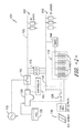
- FIG. 1 illustrates a schematic diagram of one embodiment of a hybrid power system utilizing one or more energy storage devices according to the present disclosure
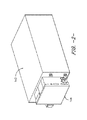
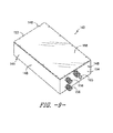
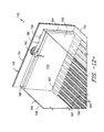
- FIG. 2 illustrates a perspective view of one embodiment of an energy storage device having reduced temperature variability between cells according to the present disclosure
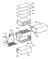
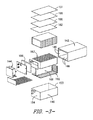
- FIG. 3 illustrates an exploded view of the energy storage device of FIG. 2 ;
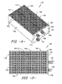
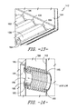
- FIG. 4 illustrates a perspective view of one embodiment of an inner housing of an energy storage device having reduced temperature variability between cells according to the present disclosure
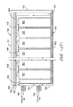
- FIG. 5 illustrates a top view of the inner housing of the energy storage device of FIG. 4 ;
- FIG. 6 illustrates a detailed view of the inner housing of the energy storage device of FIG. 5 ;
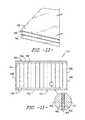
- FIG. 7 illustrates a detailed cross-sectional view of one embodiment of an electrical insulation plate according to the present disclosure
- FIG. 8 illustrates a detailed cross-sectional view of another embodiment of an electrical insulation plate according to the present disclosure
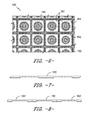
- FIG. 9 illustrates a perspective view of another embodiment of an energy storage device having reduced temperature variability between cells according to the present disclosure, particularly illustrating a thermal spreader plate and a heater configured atop the cells;
- FIG. 10 illustrates a perspective view of one embodiment of a thermal spreader plate configured between a mineral plate and a heater of the energy storage device according to the present disclosure
- FIG. 11 illustrates a cross-sectional view of the inner housing of the energy storage device of FIG. 4 ;
- FIG. 12 illustrates a partial, internal perspective view of one embodiment of the inner housing of the energy storage device of the present disclosure, particularly illustrating the manifold configured at the front side wall of the inner housing atop the insulated airflow distribution network;
- FIG. 13 illustrates a detailed, internal view of one embodiment of the energy storage device of the present disclosure, particularly illustrating the airflow distribution network of the inner housing;
- FIG. 14 illustrates a perspective view of one embodiment of an air inlet welded between the inner and outer housings of the energy storage device according to the present disclosure, particularly illustrating an annular seal configured with the air inlet;
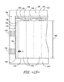
- FIG. 15 illustrates a partial side view of the energy storage device at the front side wall according to the present disclosure, particularly illustrating a manifold having a standard height
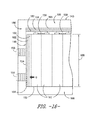
- FIG. 16 illustrates a partial side view of the energy storage device at the front side wall according to the present disclosure, particularly illustrating a manifold having a reduced height
- FIG. 17 illustrates a side view of the energy storage device according to the present disclosure, particularly illustrating the airflow from the air inlet through a sealed airflow distribution network to a top surface of the cells;
- FIG. 18 illustrates a flow diagram of one embodiment of a method for reducing temperature variability between cells of an energy storage device according to the present disclosure.
- the present disclosure is directed to an energy storage device having reduced temperature variability between cells of a cell pack.
- the present disclosure can be utilized in any suitable battery application, including but not limited to a consuming entity, a grid-connected energy storage system, and/or motive-based storage.
- the energy storage device includes an inner housing configured within an outer housing.
- the inner housing has one or more side walls that define an internal volume.
- the side walls include, at least, a bottom side wall and a front side wall, with the front side wall having an air inlet and an air outlet configured to circulate cooling air through the energy storage device.
- the energy storage device also includes a cell pack having a plurality of cells arranged in a matrix within the internal volume of the inner housing atop the bottom side wall.
- the plurality of sodium nickel chloride cells defines a top surface.
- the energy storage device includes at least one thermal spreader plate positioned on the top surface of the cell pack and/or between the cells.
- the thermal spreader plate(s) is configured to reduce temperature variability between the cells.
- the energy storage device includes a sealed airflow distribution network that circulates airflow without cooling the cells so as to reduce temperature variability across the cells when external air is provided through the air inlet.
- the present disclosure has many advantages not present in the prior art. For example, lowering the temperature gradient across the cell pack allows the cooling air blower to be run longer, which allows the pack to be cooled faster during recharge. Such faster recharge allows customers to get more energy throughput from the battery. In addition, cooling during discharge can provide longer run time for the battery by reducing the peak temperature. Further, a lower temperature also slows cell degradation and thus improves battery life.
- FIG. 1 is an illustration of one embodiment of a hybrid power system 100 , e.g. for a telecom base transceiver station (BTS), that can benefit from the energy storage device 142 of the present disclosure.
- BTS base transceiver station
- the energy storage device 142 of the present disclosure can be used in any other suitable battery application, e.g. grid-connected energy storage, utility back-up power, motive-based storage, and/or similar, and the embodiment of FIG. 1 is provided for illustrative purposes only. As shown, FIG.
- a transfer switch 115 allows transfer of operation between the AC power grid 110 and the EGS 120 , as well as other AC electrical power that may be available.
- the EGS 120 typically runs on fuel (e.g., diesel fuel) provided by a fuel source 125 (e.g., a storage tank).
- An availability switch 135 allows for alternate energy sources 130 (e.g.
- an inverter 170 (described below) can be coupled between the alternate energy source 130 and the AC bus 155 .
- the battery power source 140 is an electrical power source. More specifically, in certain embodiments, the battery power source 140 may include one or more energy storage devices, e.g. battery modules 142 . Such battery modules 142 may contain any suitable batteries known in the art. For example, in various embodiments, the battery modules 142 may contain one or more sodium nickel chloride batteries, sodium sulfur batteries, lithium ion batteries, nickel metal hydride batteries, fuel cells, or similar. More specifically, in certain embodiments, the battery modules 142 may include a plurality of sodium nickel chloride cells 162 arranged in a matrix, e.g. in a plurality of rows and columns. In addition, in particular embodiments, each of the cells 162 may include a ceramic electrolyte material that separates the electrodes of adjacent cells.
- chloride ions may be released from sodium chloride and combined with nickel to form nickel chloride.
- the sodium ions that remain can move through the electrolyte into a reservoir.
- the battery produces power, the ions move back through the electrode and the reaction is reversed.
- the process typically occurs at about 300 degrees Celsius (° C.) inside an insulated container or inner housing 146 ( FIGS. 3-5 ).
- Sodium nickel chloride batteries are particularly suitable due to their short charge times that can drive the EGS 120 to peak efficiency, thereby reducing fuel costs for the BTS.
- sodium nickel chloride battery performance is not affected by ambient temperature; therefore, such batteries can be used at sites with extreme temperature variations.
- the battery modules 142 are typically available in three size ranges, namely kWh, MWh and GWh.
- the AC bus 155 provides AC power to drive AC loads 160 of the system such as, for example, lighting and/or air conditioning of a telecom base transceiver station (BTS). Furthermore, the AC bus 155 can provide AC power to a bi-directional inverter 170 which converts AC power to DC power which provides DC power to the DC bus 145 to drive DC loads 180 of the power system 100 .
- Example DC loads of the power system 100 include radios, switches, and amplifiers of the BTS.
- the DC bus 145 also provides DC power from the inverter 170 to charge the battery power source 140 and provides DC power from the battery power source 140 to the DC loads 180 as the battery power source 140 discharges.
- the inverter 170 may regulate DC power from a DC electrical power source (e.g., a solar energy system or a fuel cell energy system) instead of an AC electrical power source.
- a primary power source may provide AC or DC electrical power that is used by an energy storage device (e.g., by the DC battery power source 140 ) of the power system 100 .
- the EGS 120 when the EGS 120 is on, the EGS 120 is configured to provide power to the DC loads 180 and to the battery power source 140 during a charging part of the cycle.
- the battery power source 140 When the EGS 120 is off, the battery power source 140 is configured to provide power to the DC loads 180 during a discharging part of the cycle.
- the battery power source 140 may be controlled by a battery management system (BMS) 144 .
- BMS battery management system
- the BMS 144 generally refers to any electronic system that manages a rechargeable battery module (e.g.
- the BMS 144 is configured to monitor and/or control operation of one or more energy storage devices (e.g. the battery modules 142 ). Further, the BMS 144 may be configured to communicate with the EGS 120 by sending a start-up command so as to start-up the engine of the EGS 120 in accordance with control logic of the BMS 144 .
- the BMS 144 may be, for example, a logic controller implemented purely in hardware, a firmware-programmable digital signal processor, or a programmable processor-based software-controlled computer.
- the power system 100 may also include a controller 190 that is configured to monitor and/or control various aspects of the power system 100 as shown in FIGS. 1 and 2 .
- the controller 190 may be configured to command the engine of the EGS 120 to turn on or off in accordance with control logic of the controller 190 .
- the controller 190 may be a separate unit (as shown) or may be part of the BMS 144 of the battery power source 140 .
- the energy storage device 142 includes an inner housing 146 contained within an outer housing 143 .
- the inner housing 146 has one or more side walls 148 that define an internal volume 150 thereof. More specifically, as shown particularly in FIGS. 3-5 and 9 and 11 , the side walls 148 include, at least, a top side wall 151 , a bottom side wall 152 , a rear side wall 153 , a front side wall 154 , and opposing side walls (i.e. right and left side walls), with the front side wall 154 being configured with an air inlet 156 and an air outlet 158 .
- the air inlet and outlets 156 , 158 may include a bellow configuration.
- the energy storage device 142 also includes a plurality of cells 162 (e.g. sodium nickel chloride cells) arranged in a matrix within the internal volume 150 of the inner housing 146 , e.g. atop the bottom side wall 152 of the inner housing 146 . Further, as shown, the cells 162 define a top surface 164 . In certain embodiments, as shown in FIGS.
- the air inlet 156 (as well as the air outlet 158 ) may be welded between the inner and outer housings 143 , 146 .
- the air inlet 156 may be further provided with one or more annular seals 195 configured to seal off cooling air entering the air inlet 156 from the cells 162 during operation.
- the air inlet 156 may be welded in place via one or more airtight welds 185 .
- the front side wall 154 of the inner housing 146 may include an electrical connector 165 configured to electrically couple the energy storage device 142 to the BMS 144 as described herein.
- the bottom side wall 152 of the inner housing 146 may also include an airflow distribution network 192 extending longitudinally from a rear side wall 153 to the front side wall 154 of the inner housing 146 .
- the airflow distribution network 192 may include one or more airflow pipes 196 covered by a sump plate 198 .
- the sump plate 198 may include a plurality of perforations 194 and/or a corrugated profile defining channels for the one or more airflow pipes 196 .
- the airflow distribution network 192 may include cooling airflow pipes 196 contained within perforated sump plate channels.
- the sump plate 198 may be configured atop the plurality of airflow pipes 196 .
- the sump plate 198 may have an alternating configuration with every other airflow pipe configured atop the sump plate 198 and alternating airflow pipes configured underneath the sump plate 198 .
- the pattern of the perforations 194 may be customized such that more air is released in the center of the cell pack and/or the rear side wall 153 , e.g., where more cooling air is needed.
- the perforations 194 are configured to allow cooling air to flow through the energy storage device with minimal pressure drop.
- the energy storage device 142 may also include one or more insulation materials 186 , 187 .
- one or more strips of the insulation material 187 may be configured atop at least a portion of the airflow distribution network 192 (e.g. atop the sump plate 198 and within the channels of the corrugated profile) so as to insulate the airflow distribution network 192 from cells 192 adjacent to the front side wall 154 of the inner housing 146 .
- Such insulation materials 187 serve to block airflow from flowing down the sump channels. In other words, the insulation materials 187 assist in forcing the cooling air to flow between the cells 162 .
- the energy storage device 142 also includes at least one thermal spreader plate 166 configured to reduce temperature variability between the cells 162 . More specifically, as shown in FIGS. 3, 9-11 and 15-16 , at least one thermal spreader plate 166 may be positioned on the top surface 164 of the plurality of cells 162 .
- the energy storage device 142 may also include at least heater 168 , e.g. positioned atop the cells 162 on the top surface 164 .
- one or more thermal spreader plates 166 may be positioned between the top surface 164 of the cells 164 and the heater 168 .
- the thermal spreader plate(s) 166 may be positioned between the cells 162 .
- the thermal spreader plate(s) 166 as described herein may be constructed of any suitable material that provides reduced temperature variability between the cells 162 of the energy storage device 142 . More specifically, in certain embodiments, the thermal spreader plate(s) 166 may be constructed, at least in part, of at least one of a metal or metal alloy.
- the metal or metal alloy may include at least one of copper, aluminum, steel, zinc, brass, iron, nickel, or similar, or any other high thermal conductivity material (e.g. graphene), or any combinations thereof.
- the spreader plate(s) 166 may be constructed of copper and nickel-plated.
- the thermal spreader plate(s) 166 may have any suitable thickness. For example, in certain embodiments, the thickness of the thermal spreader plate(s) 166 may range from about 0.5 millimeters (mm) to about 2 mm.
- the energy storage device 142 may also include one or more electrical insulation plates 182 configured therein.
- one or more electrical insulation plates 182 may be configured with the front side wall 154 of the inner housing 146 .
- one or more electrical insulation plates 182 may be configured between one or more of the cells 162 .
- the thermal spreader plate(s) 166 may be sandwiched between at least two electrical insulation plates 182 and positioned between one or more of the cells 162 .
- one or more electrical insulation plates 182 may be configured on the top surface 164 of the cells 162 , e.g. below the thermal spreader plate 166 .
- the stacked configuration include the electrical insulation plate 182 , the thermal spreader plate 166 , and the heater 168 may be supported atop the cells 162 via one or more electrical interconnects 159 .
- the electrical interconnects 159 are configured to create an air passageway, e.g. between the top surface of the cells and the electrical insulation plate 182 , which allows the exhaust air to flow to the front of the energy storage device 142 .
- the electrical insulation plate(s) 182 may be included in any other suitable location within the energy storage device 142 or any combinations thereof.
- the electrical insulation plate(s) 182 may be constructed, at least in part, of any suitable high-temperature electrical insulation material (e.g. mica) or any other suitable electrical insulation plates.
- the electrical insulation plates 182 may have any suitable cross-sectional shape.
- the electrical insulation plates 182 may have a channeled or corrugated profile. More specifically, as shown, the electrical insulation plates 182 may have a U-shaped profile. Alternatively, the electrical insulation plates 182 may have a substantially flat profile, e.g. similar to a sheet material.
- the electrical insulation plates 182 may be configured as a continuous plate ( FIG. 7 ) or a segmented plate ( FIG. 8 ).
- the energy storage device 142 may also include a manifold 184 configured between the front row of cells 162 and the front side wall 154 of the inner housing 146 to further assist with providing thermal insulation to the cells 162 .
- the manifold 184 may have a standard height, for example, of about 50% of an overall height of the inner housing 146 or greater.
- the manifold 184 may have a reduced height that is less than 50% of the overall height of the inner housing 146 so as to reduce the amount of heat that is extracted from the front cells.
- the height of the manifold 184 may be from about 5% to about 40% of the overall height 188 of the inner housing 146 .
- the manifold 184 may be configured with the airflow distribution network 192 such that incoming cooling air is sealed away from the cells 162 .
- the battery cell temperature should be maintained at a predetermined temperature (e.g. at about 280 degrees Celsius (° C.)).
- a predetermined temperature e.g. at about 280 degrees Celsius (° C.)
- the cells 162 need to be cooled using external air.
- airflow can be provided via the air inlet 156 to cool the manifold 184 which absorbs heat from the cells 162 .
- FIG. 18 a flow diagram of a method 200 for reducing temperature variability between a plurality of sodium nickel chloride cells 162 in an energy storage device 142 is illustrated. As shown at 202 , the method 200 includes providing airflow through the air inlet 156 of the energy storage device 142 . Further, as shown in FIG.
- the air inlet 156 is in fluid communication with the airflow distribution network 192 located on the bottom side wall 152 of the energy storage device 142 underneath the plurality of cells 162 .
- the airflow may be at least partially sealed (e.g. using welds, seals 195 , rolled edges, etc.) from the cells 162 so as to reduce temperature variability between the cells 162 .
- the airflow may enter the air inlet 156 and circulate through the airflow distribution network 192 /air pipes 196 that are provided underneath the cells 162 .
- the airflow may enter the airflow distribution network 192 and may exit the perforations 194 in the air pipes.
- the airflow may flow through the cells 162 using the channeled mineral plates 182 (e.g. FIGS. 7 and 8 ) and/or the rear air flow channel 157 .
- the airflow evenly cools the cells 162 as it circulates to the rear side wall 153 ( FIGS. 4 and 17 ) without further cooling the manifold 184 (which causes the front cells 162 to be cooled more than desired).
- the method 200 includes positioning at least one thermal spreader plate 166 adjacent to one or more of the plurality of cells 162 .
- the thermal spreader plate(s) 166 (as well as the optional insulation materials 186 ) within the energy storage device 142 help reduce temperature variability within the cells 162 as the airflow circulates through the housing 146 .
- the method 200 includes circulating the airflow from the airflow distribution network 192 to the top surface 164 of the energy storage device 142 and to an air outlet 158 .
- the present disclosure provides an energy storage device 142 with cells 162 that can be uniformly cooled during operation.
- the step of positioning the thermal spreader plate(s) 166 adjacent to one or more of the cells 162 may further include positioning the thermal spreader plate(s) 166 on the top surface 164 of the cells 162 .
- the step of positioning the thermal spreader plate(s) 166 adjacent to one or more of the cells 162 may also include positioning one or more thermal spreader plates 166 between one or more of the cells 162 .
- the method 200 may also include providing a heater 168 atop the plurality of cells 162 .
- the method 200 may also include positioning one or more electrical insulation plates 182 between the cells 162 and/or between the top surface 164 of the cells 162 and the heater 182 .
Landscapes
- Engineering & Computer Science (AREA)
- Manufacturing & Machinery (AREA)
- Chemical & Material Sciences (AREA)
- Chemical Kinetics & Catalysis (AREA)
- Electrochemistry (AREA)
- General Chemical & Material Sciences (AREA)
- Secondary Cells (AREA)
- Battery Mounting, Suspending (AREA)
Abstract
Description
Claims (16)
Priority Applications (4)
| Application Number | Priority Date | Filing Date | Title |
|---|---|---|---|
| US14/843,164 US9806387B2 (en) | 2015-09-02 | 2015-09-02 | Energy storage device with reduced temperature variability between cells |
| PCT/US2016/043319 WO2017039863A1 (en) | 2015-09-02 | 2016-07-21 | Energy storage device with reduced temperature variability between cells |
| EP16745353.9A EP3345243B1 (en) | 2015-09-02 | 2016-07-21 | Energy storage device with reduced temperature variability between cells |
| CN201680051061.8A CN107925138B (en) | 2015-09-02 | 2016-07-21 | Energy storage device with reduced temperature variability between cells |
Applications Claiming Priority (1)
| Application Number | Priority Date | Filing Date | Title |
|---|---|---|---|
| US14/843,164 US9806387B2 (en) | 2015-09-02 | 2015-09-02 | Energy storage device with reduced temperature variability between cells |
Publications (2)
| Publication Number | Publication Date |
|---|---|
| US20170062884A1 US20170062884A1 (en) | 2017-03-02 |
| US9806387B2 true US9806387B2 (en) | 2017-10-31 |
Family
ID=56555839
Family Applications (1)
| Application Number | Title | Priority Date | Filing Date |
|---|---|---|---|
| US14/843,164 Active 2036-01-13 US9806387B2 (en) | 2015-09-02 | 2015-09-02 | Energy storage device with reduced temperature variability between cells |
Country Status (4)
| Country | Link |
|---|---|
| US (1) | US9806387B2 (en) |
| EP (1) | EP3345243B1 (en) |
| CN (1) | CN107925138B (en) |
| WO (1) | WO2017039863A1 (en) |
Cited By (1)
| Publication number | Priority date | Publication date | Assignee | Title |
|---|---|---|---|---|
| US12362408B2 (en) | 2020-02-27 | 2025-07-15 | Lg Energy Solution, Ltd. | Battery module having structure capable of rapid cooling, and ESS comprising same |
Families Citing this family (6)
| Publication number | Priority date | Publication date | Assignee | Title |
|---|---|---|---|---|
| JP7310561B2 (en) | 2019-11-13 | 2023-07-19 | Tdk株式会社 | Stacked battery pack |
| US20210296716A1 (en) * | 2020-03-23 | 2021-09-23 | Global Graphene Group, Inc. | Battery cooling system and method of operating same |
| US11949083B2 (en) | 2020-06-11 | 2024-04-02 | Global Graphene Group, Inc. | Battery module or pack with a distributed cooling and fire protection system and method of operating same |
| FR3122946B1 (en) | 2021-05-12 | 2023-07-21 | Sogefi Air & Cooling | Battery unit with integrated temperature control or regulation means |
| US20260100453A1 (en) * | 2023-10-02 | 2026-04-09 | Wright Electric Inc. | Lightweight High Temperature Battery |
| CN118099602B (en) * | 2024-04-23 | 2024-07-23 | 南昌大学 | Battery pack |
Citations (4)
| Publication number | Priority date | Publication date | Assignee | Title |
|---|---|---|---|---|
| US3745048A (en) | 1970-12-30 | 1973-07-10 | Gen Electric | Battery cooling system |
| EP2398108A1 (en) | 2009-11-25 | 2011-12-21 | Panasonic Corporation | Battery module |
| US20130052491A1 (en) | 2011-08-26 | 2013-02-28 | Roger Neil Bull | Thermal management system for a multi-cell array |
| DE102013021531A1 (en) | 2013-12-18 | 2015-06-18 | Daimler Ag | battery |
Family Cites Families (3)
| Publication number | Priority date | Publication date | Assignee | Title |
|---|---|---|---|---|
| DE3247969C2 (en) * | 1982-12-24 | 1987-04-02 | Brown, Boveri & Cie Ag, 6800 Mannheim | High temperature storage battery |
| ATE557445T1 (en) * | 2008-08-21 | 2012-05-15 | Ceres Ip Co Ltd | IMPROVED AIR FLOW OF THE AIR GUIDE OF A FUEL CELL STACK USING AN AIR DISTRIBUTION DEVICE |
| WO2015041134A1 (en) * | 2013-09-19 | 2015-03-26 | 日本碍子株式会社 | Battery-pack case |
-
2015
- 2015-09-02 US US14/843,164 patent/US9806387B2/en active Active
-
2016
- 2016-07-21 CN CN201680051061.8A patent/CN107925138B/en active Active
- 2016-07-21 EP EP16745353.9A patent/EP3345243B1/en not_active Not-in-force
- 2016-07-21 WO PCT/US2016/043319 patent/WO2017039863A1/en not_active Ceased
Patent Citations (4)
| Publication number | Priority date | Publication date | Assignee | Title |
|---|---|---|---|---|
| US3745048A (en) | 1970-12-30 | 1973-07-10 | Gen Electric | Battery cooling system |
| EP2398108A1 (en) | 2009-11-25 | 2011-12-21 | Panasonic Corporation | Battery module |
| US20130052491A1 (en) | 2011-08-26 | 2013-02-28 | Roger Neil Bull | Thermal management system for a multi-cell array |
| DE102013021531A1 (en) | 2013-12-18 | 2015-06-18 | Daimler Ag | battery |
Non-Patent Citations (2)
| Title |
|---|
| International Search Report and Written Opinion issued in connection with corresponding Application No. PCT/US2016/043319 dated Oct. 14, 2016. |
| www.espacenet.com machine translation of the detailed description of DE 102013021531A1 (Jun. 18, 2015). * |
Cited By (1)
| Publication number | Priority date | Publication date | Assignee | Title |
|---|---|---|---|---|
| US12362408B2 (en) | 2020-02-27 | 2025-07-15 | Lg Energy Solution, Ltd. | Battery module having structure capable of rapid cooling, and ESS comprising same |
Also Published As
| Publication number | Publication date |
|---|---|
| EP3345243A1 (en) | 2018-07-11 |
| CN107925138B (en) | 2021-05-11 |
| US20170062884A1 (en) | 2017-03-02 |
| WO2017039863A1 (en) | 2017-03-09 |
| CN107925138A (en) | 2018-04-17 |
| EP3345243B1 (en) | 2021-01-27 |
Similar Documents
| Publication | Publication Date | Title |
|---|---|---|
| US9806387B2 (en) | Energy storage device with reduced temperature variability between cells | |
| EP3780250B1 (en) | Battery module, battery pack comprising same battery module, and vehicle comprising same battery pack | |
| EP2337112B1 (en) | Battery pack and vehicle including the battery pack | |
| KR101355961B1 (en) | Apparatus for containing battery pack and apparatus for cooling power storage battery pack using it | |
| CN103283063B (en) | Battery module receiving device, battery module thermostat, and power storage system including the same | |
| CN207967112U (en) | Battery module, battery pack including the same, and vehicle including the battery pack | |
| KR101097226B1 (en) | Battery pack | |
| EP3982475A1 (en) | Battery module, and battery rack and power storage device comprising battery module | |
| JP5846812B2 (en) | Battery system | |
| CN221551943U (en) | Secondary battery, battery pack, and vehicle | |
| CN102142575A (en) | Battery cell module | |
| US20090042075A1 (en) | Fuel Cell Stack | |
| US10333184B2 (en) | Heat flux assembly for an energy storage device | |
| KR102053963B1 (en) | Battery pack and vehicle comprising the same | |
| US11631913B2 (en) | Assembly of battery cells, and aircraft comprising such an assembly | |
| JP2013222603A (en) | Secondary battery, secondary battery module incorporating secondary battery and battery pack system incorporating secondary battery module | |
| US20160111760A1 (en) | Power storage module | |
| JP2020004716A (en) | Battery system architecture permitting single cell abnormality | |
| CN121605526A (en) | Methods for thermal management of energy storage systems and energy storage systems | |
| US20150221998A1 (en) | Energy Storage System Preventing Self from Overheating and Method for Preventing Energy Storage System from Overheating | |
| EP3347933B1 (en) | Energy storage device having improved thermal performance | |
| JP5937341B2 (en) | Secondary battery, secondary battery system, secondary battery and method for reducing discharge reserve of secondary battery system | |
| US11888136B2 (en) | Battery, power consumption device, and method and device for producing battery | |
| Nema et al. | Electrochemical-thermal coupled modeling of a serpentine-shaped liquid cooling channel for lithium-ion battery packs with high discharge rates | |
| KR20180110937A (en) | Lithium secondary battery module, lithium secondary battery pack comprising the same, and control method of lithium ion battery |
Legal Events
| Date | Code | Title | Description |
|---|---|---|---|
| AS | Assignment |
Owner name: GENERAL ELECTRIC COMPANY, NEW YORK Free format text: ASSIGNMENT OF ASSIGNORS INTEREST;ASSIGNORS:FRUTSCHY, KRISTOPHER JOHN;LINDSEY, JAMES S.;BHAMIDIPATI, KANTHI LATHA;AND OTHERS;SIGNING DATES FROM 20150825 TO 20150902;REEL/FRAME:036478/0434 |
|
| STCF | Information on status: patent grant |
Free format text: PATENTED CASE |
|
| MAFP | Maintenance fee payment |
Free format text: PAYMENT OF MAINTENANCE FEE, 4TH YEAR, LARGE ENTITY (ORIGINAL EVENT CODE: M1551); ENTITY STATUS OF PATENT OWNER: LARGE ENTITY Year of fee payment: 4 |
|
| AS | Assignment |
Owner name: EDISON INNOVATIONS, LLC, TEXAS Free format text: ASSIGNMENT OF ASSIGNORS INTEREST;ASSIGNOR:DOLBY INTELLECTUAL PROPERTY LICENSING, LLC;REEL/FRAME:070293/0273 Effective date: 20250219 |
|
| AS | Assignment |
Owner name: GE INTELLECTUAL PROPERTY LICENSING, LLC, NEW YORK Free format text: ASSIGNMENT OF ASSIGNORS INTEREST;ASSIGNOR:GENERAL ELECTRIC COMPANY;REEL/FRAME:070636/0815 Effective date: 20240630 Owner name: DOLBY INTELLECTUAL PROPERTY LICENSING, LLC, NEW YORK Free format text: CHANGE OF NAME;ASSIGNOR:GE INTELLECTUAL PROPERTY LICENSING, LLC;REEL/FRAME:070643/0907 Effective date: 20240819 |
|
| MAFP | Maintenance fee payment |
Free format text: PAYMENT OF MAINTENANCE FEE, 8TH YEAR, LARGE ENTITY (ORIGINAL EVENT CODE: M1552); ENTITY STATUS OF PATENT OWNER: LARGE ENTITY Year of fee payment: 8 |
|
| AS | Assignment |
Owner name: BUNKER HILL TECHNOLOGIES, LLC, TEXAS Free format text: QUITCLAIM ASSIGNMENT;ASSIGNOR:EDISON INNOVATIONS LLC;REEL/FRAME:074326/0549 Effective date: 20250918 |