US9805752B2 - Selective write power variability for magnetic recording - Google Patents
Selective write power variability for magnetic recording Download PDFInfo
- Publication number
- US9805752B2 US9805752B2 US14/938,298 US201514938298A US9805752B2 US 9805752 B2 US9805752 B2 US 9805752B2 US 201514938298 A US201514938298 A US 201514938298A US 9805752 B2 US9805752 B2 US 9805752B2
- Authority
- US
- United States
- Prior art keywords
- data
- track
- tracks
- writing
- band
- Prior art date
- Legal status (The legal status is an assumption and is not a legal conclusion. Google has not performed a legal analysis and makes no representation as to the accuracy of the status listed.)
- Active
Links
Images


Classifications
-
- G—PHYSICS
- G11—INFORMATION STORAGE
- G11B—INFORMATION STORAGE BASED ON RELATIVE MOVEMENT BETWEEN RECORD CARRIER AND TRANSDUCER
- G11B5/00—Recording by magnetisation or demagnetisation of a record carrier; Reproducing by magnetic means; Record carriers therefor
- G11B5/48—Disposition or mounting of heads or head supports relative to record carriers ; arrangements of heads, e.g. for scanning the record carrier to increase the relative speed
- G11B5/58—Disposition or mounting of heads or head supports relative to record carriers ; arrangements of heads, e.g. for scanning the record carrier to increase the relative speed with provision for moving the head for the purpose of maintaining alignment of the head relative to the record carrier during transducing operation, e.g. to compensate for surface irregularities of the latter or for track following
- G11B5/60—Fluid-dynamic spacing of heads from record-carriers
- G11B5/6005—Specially adapted for spacing from a rotating disc using a fluid cushion
- G11B5/6011—Control of flying height
- G11B5/6041—Control of flying height using magnetic forces
-
- G—PHYSICS
- G11—INFORMATION STORAGE
- G11B—INFORMATION STORAGE BASED ON RELATIVE MOVEMENT BETWEEN RECORD CARRIER AND TRANSDUCER
- G11B5/00—Recording by magnetisation or demagnetisation of a record carrier; Reproducing by magnetic means; Record carriers therefor
- G11B5/012—Recording on, or reproducing or erasing from, magnetic disks
-
- G—PHYSICS
- G11—INFORMATION STORAGE
- G11B—INFORMATION STORAGE BASED ON RELATIVE MOVEMENT BETWEEN RECORD CARRIER AND TRANSDUCER
- G11B20/00—Signal processing not specific to the method of recording or reproducing; Circuits therefor
- G11B20/10—Digital recording or reproducing
- G11B20/10009—Improvement or modification of read or write signals
- G11B20/10018—Improvement or modification of read or write signals analog processing for digital recording or reproduction
- G11B20/10027—Improvement or modification of read or write signals analog processing for digital recording or reproduction adjusting the signal strength during recording or reproduction, e.g. variable gain amplifiers
-
- G—PHYSICS
- G11—INFORMATION STORAGE
- G11B—INFORMATION STORAGE BASED ON RELATIVE MOVEMENT BETWEEN RECORD CARRIER AND TRANSDUCER
- G11B20/00—Signal processing not specific to the method of recording or reproducing; Circuits therefor
- G11B20/10—Digital recording or reproducing
- G11B20/12—Formatting, e.g. arrangement of data block or words on the record carriers
- G11B20/1217—Formatting, e.g. arrangement of data block or words on the record carriers on discs
-
- G—PHYSICS
- G11—INFORMATION STORAGE
- G11B—INFORMATION STORAGE BASED ON RELATIVE MOVEMENT BETWEEN RECORD CARRIER AND TRANSDUCER
- G11B5/00—Recording by magnetisation or demagnetisation of a record carrier; Reproducing by magnetic means; Record carriers therefor
- G11B5/02—Recording, reproducing, or erasing methods; Read, write or erase circuits therefor
- G11B5/09—Digital recording
-
- G—PHYSICS
- G11—INFORMATION STORAGE
- G11B—INFORMATION STORAGE BASED ON RELATIVE MOVEMENT BETWEEN RECORD CARRIER AND TRANSDUCER
- G11B5/00—Recording by magnetisation or demagnetisation of a record carrier; Reproducing by magnetic means; Record carriers therefor
- G11B5/48—Disposition or mounting of heads or head supports relative to record carriers ; arrangements of heads, e.g. for scanning the record carrier to increase the relative speed
- G11B5/58—Disposition or mounting of heads or head supports relative to record carriers ; arrangements of heads, e.g. for scanning the record carrier to increase the relative speed with provision for moving the head for the purpose of maintaining alignment of the head relative to the record carrier during transducing operation, e.g. to compensate for surface irregularities of the latter or for track following
- G11B5/60—Fluid-dynamic spacing of heads from record-carriers
- G11B5/6005—Specially adapted for spacing from a rotating disc using a fluid cushion
- G11B5/6011—Control of flying height
- G11B5/607—Control of flying height using thermal means
-
- G—PHYSICS
- G11—INFORMATION STORAGE
- G11B—INFORMATION STORAGE BASED ON RELATIVE MOVEMENT BETWEEN RECORD CARRIER AND TRANSDUCER
- G11B5/00—Recording by magnetisation or demagnetisation of a record carrier; Reproducing by magnetic means; Record carriers therefor
- G11B5/48—Disposition or mounting of heads or head supports relative to record carriers ; arrangements of heads, e.g. for scanning the record carrier to increase the relative speed
- G11B5/58—Disposition or mounting of heads or head supports relative to record carriers ; arrangements of heads, e.g. for scanning the record carrier to increase the relative speed with provision for moving the head for the purpose of maintaining alignment of the head relative to the record carrier during transducing operation, e.g. to compensate for surface irregularities of the latter or for track following
- G11B5/60—Fluid-dynamic spacing of heads from record-carriers
- G11B5/6005—Specially adapted for spacing from a rotating disc using a fluid cushion
- G11B5/6082—Design of the air bearing surface
-
- G—PHYSICS
- G11—INFORMATION STORAGE
- G11B—INFORMATION STORAGE BASED ON RELATIVE MOVEMENT BETWEEN RECORD CARRIER AND TRANSDUCER
- G11B20/00—Signal processing not specific to the method of recording or reproducing; Circuits therefor
- G11B20/10—Digital recording or reproducing
- G11B20/12—Formatting, e.g. arrangement of data block or words on the record carriers
- G11B20/1217—Formatting, e.g. arrangement of data block or words on the record carriers on discs
- G11B2020/1218—Formatting, e.g. arrangement of data block or words on the record carriers on discs wherein the formatting concerns a specific area of the disc
- G11B2020/1238—Formatting, e.g. arrangement of data block or words on the record carriers on discs wherein the formatting concerns a specific area of the disc track, i.e. the entire a spirally or concentrically arranged path on which the recording marks are located
Definitions
- ADC areal density capability
- TPI tracks per inch
- BPI bits per inch
- the tracks per inch value is sometimes referred to as “radial density”, while the bits per inch value may be referred to as the “recording density”, “bit density”, or “linear density.”
- BER bit error rate
- TPI and BPI values are configured with preset TPI and BPI values selected to achieve a high ADC while maintaining an acceptable BER.
- a number of challenges are associated with increasing drive TPI and BPI beyond current limits.
- FIG. 1 illustrates a data storage device including a transducer head assembly for writing data on a magnetic storage medium.
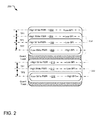
- FIG. 2 illustrates techniques for selectively altering write power to increase areal density capability (ADC) of a magnetic storage medium.
- ADC areal density capability
- FIG. 3 illustrates one example technique for selectively altering write power when writing to certain tracks on a storage medium.
- FIG. 4 illustrates a plot illustrating example write current parameters that may be altered to decrease write power when writing to select data tracks on a storage medium.
- FIG. 5 illustrates example operations for selecting a write power for use in association with select data tracks of a storage device.
- FIG. 6 illustrates example operations for dynamically adjusting write power when writing to select data tracks on a storage medium.
- One implementation of the disclosed technology provides a storage controller that controls a writer to generate a magnetic field at an air-bearing surface (ABS) of a storage medium and to selectively alter the strength of the magnetic field by a predetermined amount when writing data to select data tracks on the storage medium.
- ABS air-bearing surface
- a storage device controller disclosed herein increases fly height of a writer by a predetermined amount when writing data to select data tracks on a storage medium to decrease a written width of select data tracks.
- a storage device controller alters a write current parameter by a predetermined amount when writing to select data tracks on a storage medium to decrease a written width of the select data tracks.
- FIG. 1 illustrates a data storage device 100 including a transducer head assembly 120 for writing data on a magnetic storage medium 108 .
- the magnetic storage medium 108 is, in FIG. 1 , a magnetic storage disc on which data bits can be recorded using a magnetic write pole (not shown) and from which data bits can be read using a magnetoresistive element (not shown).
- the magnetic storage medium 108 rotates about a spindle center or a disc axis of rotation 112 during rotation, and includes an inner diameter 104 and an outer diameter 102 between which are a number of concentric data tracks 110 .
- Information may be written to and read from data bit locations in the data tracks on the magnetic storage medium 108 .
- the transducer head assembly 120 is mounted on an actuator assembly 109 at an end distal to an actuator axis of rotation 114 .
- the transducer head assembly 120 flies in close proximity above the surface of the magnetic storage medium 108 during disc rotation.
- the actuator assembly 109 rotates during a seek operation about the disc axis of rotation 112 .
- the seek operation positions the transducer head assembly 120 over a target data track for read and write operations.
- a writer (not shown) of the transducer head assembly 120 converts a series of electrical pulses sent from a controller 106 into a series of magnetic pulses of commensurate magnitude and length, and the magnetic pulses selectively magnetize magnetic grains of the magnetic storage medium 108 as they pass below the transducer head assembly 120 .
- the controller 106 includes software and/or hardware, and may be implemented in any tangible computer-readable storage media within or communicatively coupled to the data storage device 100 .
- tangible computer-readable storage media includes, but is not limited to, RAM, ROM, EEPROM, flash memory or other memory technology, CDROM, digital versatile disks (DVD) or other optical disk storage, magnetic cassettes, magnetic tape, magnetic disk storage or other magnetic storage devices, or any other tangible medium which can be used to store the desired information and which can accessed by mobile device or computer.
- intangible computer-readable communication signals may embody computer readable instructions, data structures, program modules or other data resident in a modulated data signal, such as a carrier wave or other signal transport mechanism.
- modulated data signal means a signal that has one or more of its characteristics set or changed in such a manner as to encode information in the signal.
- the controller 106 includes (or is communicatively coupled to) a write power variation module 116 .
- the write power variation module 116 controls the transducer head assembly 120 to selectively increase or decrease write power when writing to select data tracks on the magnetic storage medium 108 .
- write power refers to strength of a magnetic field produced by a writer (also referred to as a write element) as measured on an air-bearing surface (ABS) of the magnetic storage medium 108 . Altering write power can also impact the width of a corresponding written write track. For this reason, selective variance of write power can impact a number of tracks per inch (TPI) on the storage medium 108 .
- the write power variation module 116 selectively increases and decreases write power when writing data to select data tracks.
- Altering write power can be accomplished in different ways.
- the write power variation module 116 increases or decreases write power by altering a clearance between the transducer head assembly 120 and the storage medium 108 .
- the write power variation module 116 selectively increases or decreases write power by altering a write current parameter.
- write current parameter refers to a parameter setting that influences shape or size of a magnetic pulse produced by a writer of the transducer head assembly 120 .
- the following discussion details an example data management scheme employing the write power variation module 116 to improve drive overhead and recording capacity in a shingled magnetic recording system. It should be understood that the example functions served by the write power variation module 116 may also be useful in implementing a variety of other data management schemes not discussed herein, including those with applications in systems that do not utilize shingled magnetic recording.
- View B illustrates data tracks of the magnetic storage medium 108 when the data tracks are storing data according to a shingled magnetic recording (SMR) technique.
- SMR is one way to decrease the size of data cells on the magnetic storage medium 108 without a corresponding decrease in the size of a writer on the transducer head assembly 120 .
- a magnetic field produced by the writer is strong enough to affect two adjacent data tracks on the magnetic storage medium 108 on a single pass of the writer.
- a magnetic footprint 156 e.g., an area of the storage medium magnetically polarized by the writer on a single pass
- the magnetic footprint 156 has a width W 1 that is equal in width to a width of data tracks 132 and 134 combined. Therefore, an initial write to the data track 132 incidentally magnetizes (e.g., corrupts) data on the adjacent data track 134 .
- the corrupted data in the data track 134 can be corrected on a subsequent pass of the writer over the data track 134 , but this data write to the data track 134 in turn corrupts data on data track 136 , and so on.
- data tracks on the data storage device 100 are generally grouped into data bands (e.g., data bands 138 , 140 ), where each data band is separated from other adjacent data bands by one or more guard tracks (e.g., guard tracks 152 and 154 ) where no data is stored.
- the storage device 100 reads all data tracks in the associated data band 138 (e.g., including data tracks 132 , 134 , 136 , and 142 ) into a memory location in a consecutive order.
- the data storage device 100 updates the one or more data cells to be changed by the write operation and then re-writes, in a consecutive order, the data tracks 132 , 134 , 136 , and 142 including the one or more updated cells.
- the width W 1 of the writer's magnetic footprint 156 corresponds to two data tracks
- a pass of the writer over the last data track in a band may affect some data region below it (e.g., a data region 150 ) where no meaningful data is actually stored. Due to inclusion of this extra space, the data tracks 142 and 148 are also referred to herein as “FAT data tracks.” If the write center of the FAT data track 142 is defined by an axis C 1 , the data region 150 is potentially wasted space. If, on the other hand, the write center of the FAT data track 142 is shifted slightly to a position C 2 , a number of techniques can be realized to boost ADC of the magnetic storage medium 108 .
- shifting the center of the FAT data track 142 away from the adjacent data-storing tracks 136 reduces a risk of adjacent track interference (ATI) to the immediately adjacent data track.
- ATI adjacent track interference
- shifting the center of the FAT data track 142 away from the data track 136 reduces a risk of ATI to the data track 136 .
- a linear density (bits per inch, BPI) of the FAT data tracks can be increased as compared to other data tracks in the data band 138 without increasing the observed ATI or bit error rate (BER). This allows for a net increase in BPI on the data storage medium. This is technique is explored in greater detail with respect to FIG. 2 .
- the center of the data track 148 is shifted away from the adjacent data-storing track, as described above. After this shift, a write center of the data track 148 is defined by the axis C 3 . Write power is then decreased when writing to the data track 148 to further increase ADC of the storage medium and reduce SMR overhead.
- the magnetic footprint 156 of the writer can be reduced from a width W 1 to a smaller width W 2 , as shown.
- This reduction in the magnetic footprint width (W 1 to W 2 ) is accomplished by reducing write power (e.g., a strength of the magnetic field of the writer at the ABS) during the write operation, such as by increasing clearance between the magnetic storage medium 108 and the transducer head assembly 120 or by reducing a write current parameter.
- a total width spanned by data of the last data track 148 is still greater than the other data tracks in the data band (e.g., data tracks 144 , 146 ), which each include data bits spanning approximately 1 ⁇ 2 of W 1 .
- Decreasing the magnetic footprint of the writer (as shown) when writing to the last data track in each SMR data band 138 , 140 allows the data bands to be spaced closer together, increasing a total TPI on the storage medium.
- the write power variation module 116 selectively alters strength of a magnetic field incident on the storage medium when writing to select tracks other than or in addition to the last data tracks (e.g., 142 , 148 ) in each of a number of SMR data bands. In one example alternate implementation, the write power variation module 116 selectively decreases power incrementally when sequentially writing to the data tracks 144 , 146 , 148 so that the data track 144 has a greater written track width than the data track 146 and the data track 146 has a greater written track width that the data track 148 . In still another implementation, write power variation module 116 is implemented in a device that does not utilize SMR.
- the write power variation module 116 may selectively decrease strength of a magnetic field incident on the storage medium when writing to select data tracks in a conventional magnetic recording device or when writing to every-other data track on a storage medium, such as in a storage device implementing an interlaced magnetic recording technique.
- FIG. 2 illustrates further techniques for selectively altering write power to increase ADC on a magnetic storage medium 200 in a shingled magnetic storage system.
- the shingled magnetic storage system includes a number of data tracks organized into data bands (e.g., data bands 218 and 220 ) such that each data band is separated from the immediately adjacent data band by guard tracks where no data is stored.
- a last data track in each of the data bands 218 and 220 is defined to have a different track pitch (TP) than other tracks of the data bands.
- the “track pitch” refers to a distance between write centers of two immediately adjacent data tracks (e.g., write centers indicated by dotted lines in FIG. 2 ).
- the data track 208 has a write center separated from the write center of the nearest adjacent data track 206 by a track pitch TP 2 , which is larger than a track pitch TP 1 of other adjacent data tracks in the same data band 218 . Due in part to this slight adjustment in track pitch, there is decreased risk that a data write to the data track 208 will incidentally corrupt data on the adjacent track 206 through adjacent track interference (ATI). For this reason, linear density and write power can be manipulated during data writes to the data tracks 208 and 216 to increase ADC of the storage medium 200 .
- ATI adjacent track interference
- the linear density (BPI) of the data tracks 208 and 216 is increased as compared to the other data tracks in the data band.
- a controller of the shingled magnetic storage system selectively decreases write power when writing data to the data tracks 208 and 216 . Although this decrease in write power decreases the size of the writer's magnetic footprint (as seen by the difference in dotted and solid track outlines of the data tracks 208 and 216 ), a bit error rate (BER) of data read back from the last data tracks 208 and 216 is still within an acceptable range due to the increased associated track pitch (TP 2 ).
- BER bit error rate
- FIG. 3 illustrates an example of altering a clearance 304 between a transducer head 302 and a storage medium 308 in a storage device 300 when writing to select data tracks on the storage medium 308 .
- An increase in the clearance 304 causes a proportional decrease in write power (e.g., strength of a magnetic field produced by a writer 306 and measured at an ABS of the storage medium 308 ). That is, as the clearance 304 or “fly height” is increased, an area 310 on the of the storage medium 300 capable of being magnetically polarized by a pass of the writer 306 shrinks
- a decrease in the clearance 304 is proportional to an increase in size of the area 310 capable of being magnetically polarized by a pass of the writer 306 .
- a decrease in the clearance 304 corresponds to an increase in a pitch angle a of the transducer head 302
- an increase in the clearance 304 corresponds to an increase in the pitch angle ⁇ .
- the clearance 304 is selectively decreased during data writes to a last data track in each SMR data band.
- the clearance 304 may be decreased by an amount sufficient to reduce write power by about 20%.
- FIG. 4 illustrates a plot 400 illustrating example write current parameters that may be altered to decrease write power when writing to select data tracks on a storage medium (not shown).
- the plot 400 illustrates overlaid example write current pulses 402 , 404 , 406 .
- Each pulse is defined by a steady state write current (e.g., write current 408 ), an overshoot 410 , and a duration 412 for the overshoot 410 .
- Write power (as measured at the ABS) is selectively decreased when one or more of the illustrated write current parameters (e.g., the write current 408 , the overshoot 410 , or the duration 412 ) are also decreased.
- one or more of the illustrated write current parameters are selectively decreased when writing data to a last data track in each SMR data band.
- the magnitude of this decrease is determined by specific details of the transducer head, media design, and corresponding data rate.
- the write power e.g., as measured at the ABS
- the write power is decreased by about 20% when writing to the last data track in each data band as compared to the other data tracks in the corresponding data band. This decrease in write power ultimately allows for an increase in the number of data tracks on the storage medium (tracks per inch, TPI).
- FIG. 5 illustrates example operations 500 for selecting write power in association with select data tracks of a storage device.
- the operations of FIG. 5 occur during a factory formatting process.
- a first selection and measuring operation 505 selects an SMR data band on the storage medium.
- a test write operation 510 writes test data to a last data track of the SMR data band (e.g., the “FAT” data track).
- a measuring operation 515 reads the test data from the FAT data track of the SMR data band and measures a bit error rate (BER).
- BER bit error rate
- a determination operation 520 determines whether the measured BER is greater than some predefined criterion.
- the predefined criterion corresponds to a number of read errors close to or including a maximum number of acceptable errors (or range of acceptable errors) that can still be corrected by an error correction code of the storage device. If the measured BER of the FAT track is still greater than the predefined criterion, a write power adjustment operation 530 decreases write power and the writing operation 510 again writes the test data to the FAT data track. The measuring operation 515 re-measures the resulting BER of the FAT data track. The operations 510 , 515 , 520 , and 530 repeat until the measured BER of the FAT track is less than or equal to the predefined criterion. At this point, a setting operation 525 records the current write power in association with the FAT data track. For example, the current write power may be stored in association with the FAT data track in a firmware table of the data storage device.
- the operations 505 through 530 repeat for each “FAT” track on the data storage device, until a pre-determined write power is saved in association with each FAT data track of the data storage device.
- the write power values may be stored directly or indirectly, such as in the form of writer-media clearance values or one or more write current parameters sufficient to generate the write power.
- Other operations may define the boundaries for each data band and the amount of isolation (guard track width) between adjacent data bands.
- FIG. 6 illustrates example operations 600 for dynamically adjusting write power when writing to select data tracks on a storage medium.
- a receiving instruction 605 receives an instruction to write data to a target data track.
- a determination operation 610 determines if the target data track belongs to a predetermined subset of data tracks associated, in memory, with a decreased write power.
- the storage medium may be implemented in a shingled magnetic recording system and the last data track (e.g., the FAT track) of each data band may be designated as a data track that is to be written at lower write power than the other data tracks in the associated data band.
- the determination operation 610 may be performed, for example, by accessing a table stored in firmware of the storage device and identifying a write current parameter or a clearance parameter associated with the target data track.
- a write operation 625 writes the to the target data track at a default write power. If, on the other hand, the determination operation 610 determines that the target data track does belong to the predetermined subset of data tracks, the write power adjustment operation 615 adjusts the write power to a value other than the default value. In one implementation, the write power adjustment operation 615 decreases write power by increasing a clearance between the storage medium and a transducer head. In another implementation, the write power adjustment operation 615 adjusts write power by decreasing a write power parameter such as current, overshoot, or duration. A writing operation 620 writes the data to the target data track with the adjusted write power.
- the embodiments of the disclosed technology described herein are implemented as logical steps in one or more computer systems.
- the logical operations of the presently disclosed technology are implemented (1) as a sequence of processor-implemented steps executing in one or more computer systems and (2) as interconnected machine or circuit modules within one or more computer systems.
- the implementation is a matter of choice, dependent on the performance requirements of the computer system implementing the disclosed technology. Accordingly, the logical operations making up the embodiments of the disclosed technology described herein are referred to variously as operations, steps, objects, or modules.
- logical operations may be performed in any order, adding and omitting as desired, unless explicitly claimed otherwise or a specific order is inherently necessitated by the claim language.
Landscapes
- Engineering & Computer Science (AREA)
- Signal Processing (AREA)
- Digital Magnetic Recording (AREA)
- Recording Or Reproducing By Magnetic Means (AREA)
- Magnetic Heads (AREA)
Abstract
Description
Claims (20)
Priority Applications (1)
| Application Number | Priority Date | Filing Date | Title |
|---|---|---|---|
| US14/938,298 US9805752B2 (en) | 2015-11-11 | 2015-11-11 | Selective write power variability for magnetic recording |
Applications Claiming Priority (1)
| Application Number | Priority Date | Filing Date | Title |
|---|---|---|---|
| US14/938,298 US9805752B2 (en) | 2015-11-11 | 2015-11-11 | Selective write power variability for magnetic recording |
Publications (2)
| Publication Number | Publication Date |
|---|---|
| US20170133047A1 US20170133047A1 (en) | 2017-05-11 |
| US9805752B2 true US9805752B2 (en) | 2017-10-31 |
Family
ID=58663663
Family Applications (1)
| Application Number | Title | Priority Date | Filing Date |
|---|---|---|---|
| US14/938,298 Active US9805752B2 (en) | 2015-11-11 | 2015-11-11 | Selective write power variability for magnetic recording |
Country Status (1)
| Country | Link |
|---|---|
| US (1) | US9805752B2 (en) |
Cited By (3)
| Publication number | Priority date | Publication date | Assignee | Title |
|---|---|---|---|---|
| US20180182432A1 (en) * | 2016-12-22 | 2018-06-28 | Seagate Technology Llc | Shingled Magnetic Recording with Operational Based Track Spacing |
| US11004468B2 (en) * | 2019-06-28 | 2021-05-11 | Kabushiki Kaisha Toshiba | Magnetic disk device and method for adjusting write data |
| US20230109214A1 (en) * | 2021-09-17 | 2023-04-06 | Kabushiki Kaisha Toshiba | Magnetic disk device and method of changing recording mode |
Families Citing this family (2)
| Publication number | Priority date | Publication date | Assignee | Title |
|---|---|---|---|---|
| US9830940B1 (en) | 2016-05-13 | 2017-11-28 | Seagate Technology Llc | Heat-assisted shingled magnetic recording with variable track widths |
| US11532327B2 (en) * | 2020-04-28 | 2022-12-20 | Seagate Technology Llc | Reader fly height control for head burnishing mitigation |
Citations (6)
| Publication number | Priority date | Publication date | Assignee | Title |
|---|---|---|---|---|
| US7193807B1 (en) * | 2000-09-15 | 2007-03-20 | Maxtor Corporation | Method and apparatus for reducing effective track width through highly skewed head angles |
| US8300345B2 (en) | 2008-12-04 | 2012-10-30 | Doug Carson & Associates, Inc. | Variable track width recording compensation |
| US8867161B2 (en) * | 2013-03-15 | 2014-10-21 | Seagate Technology Llc | Shingled magnetic recording with variable track spacing |
| US8941943B1 (en) * | 2013-12-09 | 2015-01-27 | HGST Netherlands B.V. | Dynamic variable capacity hard disk drive |
| US9111578B1 (en) | 2014-07-23 | 2015-08-18 | Seagate Technology Llc | Recording density variation of data tracks |
| US9318139B2 (en) * | 2012-07-25 | 2016-04-19 | Marvell International Ltd. | Recording medium, a data storage apparatus and a method of preparing a recording medium |
-
2015
- 2015-11-11 US US14/938,298 patent/US9805752B2/en active Active
Patent Citations (6)
| Publication number | Priority date | Publication date | Assignee | Title |
|---|---|---|---|---|
| US7193807B1 (en) * | 2000-09-15 | 2007-03-20 | Maxtor Corporation | Method and apparatus for reducing effective track width through highly skewed head angles |
| US8300345B2 (en) | 2008-12-04 | 2012-10-30 | Doug Carson & Associates, Inc. | Variable track width recording compensation |
| US9318139B2 (en) * | 2012-07-25 | 2016-04-19 | Marvell International Ltd. | Recording medium, a data storage apparatus and a method of preparing a recording medium |
| US8867161B2 (en) * | 2013-03-15 | 2014-10-21 | Seagate Technology Llc | Shingled magnetic recording with variable track spacing |
| US8941943B1 (en) * | 2013-12-09 | 2015-01-27 | HGST Netherlands B.V. | Dynamic variable capacity hard disk drive |
| US9111578B1 (en) | 2014-07-23 | 2015-08-18 | Seagate Technology Llc | Recording density variation of data tracks |
Non-Patent Citations (2)
| Title |
|---|
| U.S. Appl. No. 14/685,417, filed Apr. 13, 2015. |
| U.S. Appl. No. 14/686,456, filed Apr. 14, 2015. |
Cited By (5)
| Publication number | Priority date | Publication date | Assignee | Title |
|---|---|---|---|---|
| US20180182432A1 (en) * | 2016-12-22 | 2018-06-28 | Seagate Technology Llc | Shingled Magnetic Recording with Operational Based Track Spacing |
| US10056109B2 (en) * | 2016-12-22 | 2018-08-21 | Seagate Technology Llc | Shingled magnetic recording with operational based track spacing |
| US11004468B2 (en) * | 2019-06-28 | 2021-05-11 | Kabushiki Kaisha Toshiba | Magnetic disk device and method for adjusting write data |
| US20230109214A1 (en) * | 2021-09-17 | 2023-04-06 | Kabushiki Kaisha Toshiba | Magnetic disk device and method of changing recording mode |
| US11735221B2 (en) * | 2021-09-17 | 2023-08-22 | Kabushiki Kaisha Toshiba | Magnetic disk device and method of changing recording mode |
Also Published As
| Publication number | Publication date |
|---|---|
| US20170133047A1 (en) | 2017-05-11 |
Similar Documents
| Publication | Publication Date | Title |
|---|---|---|
| US9728206B2 (en) | Interlaced magnetic recording | |
| US10090016B2 (en) | Variable written track widths for attribute-based storage | |
| US8085487B1 (en) | Blocking formats for a disk drive that reduce performance | |
| US7656603B1 (en) | Pre-programming of a preamplifier in a disk drive to improve servo-writing characteristics | |
| US9111578B1 (en) | Recording density variation of data tracks | |
| US9142252B2 (en) | Magnetic disk drive and data rewrite methods | |
| US8031423B1 (en) | Disk drive generating actual data TPI profile by combining segments of predetermined data TPI profiles | |
| US9805752B2 (en) | Selective write power variability for magnetic recording | |
| US8018672B2 (en) | Magnetic recording device and magnetic recording method thereof | |
| US20160148644A1 (en) | Prioritized random access for magnetic recording | |
| US10008231B2 (en) | Shingled magnetic recording for writing tracks of variable track width | |
| US9230605B1 (en) | Data storage device maximizing areal density based on a target quality metric | |
| TW200842833A (en) | Disk drive device and data rewrite method thereof | |
| US9842047B2 (en) | Non-sequential write for sequential read back | |
| US9747928B1 (en) | Data storage device modifying write operation when a laser mode hop is detected | |
| US20150255099A1 (en) | Disk drive employing multiple read elements to increase radial band for two-dimensional magnetic recording | |
| US9070406B1 (en) | Disk drive configuring one-dimensional and two-dimensional recording areas based on read element spacing | |
| US8000046B2 (en) | Storage device, processor or storage device, and computer program product for providing parameter adjustment during read/write operations | |
| US9805741B1 (en) | Write current parameter selection for magnetic recording | |
| US9672851B1 (en) | Single writer interlaced magnetic recording | |
| US20100191905A1 (en) | Storage device, control method and controller | |
| US10770095B2 (en) | Recording density setting method based on linear recording densit and track pitch limiting | |
| US10347285B1 (en) | Microwave assisted magnetic recording drive utilizing interlaced track recording | |
| US9064525B2 (en) | Disk drive comprising laser transmission line optimized for heat assisted magnetic recording | |
| US8023221B1 (en) | Position gain calibration in disk drives |
Legal Events
| Date | Code | Title | Description |
|---|---|---|---|
| AS | Assignment |
Owner name: SEAGATE TECHNOLOGY LLC, CALIFORNIA Free format text: ASSIGNMENT OF ASSIGNORS INTEREST;ASSIGNORS:YOON, JUNG MIN;CHUNG, JAE MYUNG;KIM, HWAJUN;REEL/FRAME:037014/0588 Effective date: 20151111 |
|
| STCF | Information on status: patent grant |
Free format text: PATENTED CASE |
|
| MAFP | Maintenance fee payment |
Free format text: PAYMENT OF MAINTENANCE FEE, 4TH YEAR, LARGE ENTITY (ORIGINAL EVENT CODE: M1551); ENTITY STATUS OF PATENT OWNER: LARGE ENTITY Year of fee payment: 4 |
|
| AS | Assignment |
Owner name: AVAGO TECHNOLOGIES INTERNATIONAL SALES PTE. LIMITED, SINGAPORE Free format text: ASSIGNMENT OF ASSIGNORS INTEREST;ASSIGNORS:SEAGATE TECHNOLOGY LLC;SEAGATE SINGAPORE INTERNATIONAL HEADQUARTERS PTE. LTD.;REEL/FRAME:067489/0509 Effective date: 20240423 Owner name: AVAGO TECHNOLOGIES INTERNATIONAL SALES PTE. LIMITED, SINGAPORE Free format text: ASSIGNMENT OF ASSIGNOR'S INTEREST;ASSIGNORS:SEAGATE TECHNOLOGY LLC;SEAGATE SINGAPORE INTERNATIONAL HEADQUARTERS PTE. LTD.;REEL/FRAME:067489/0509 Effective date: 20240423 |
|
| MAFP | Maintenance fee payment |
Free format text: PAYMENT OF MAINTENANCE FEE, 8TH YEAR, LARGE ENTITY (ORIGINAL EVENT CODE: M1552); ENTITY STATUS OF PATENT OWNER: LARGE ENTITY Year of fee payment: 8 |