US980573A - Dust-guard. - Google Patents
Dust-guard. Download PDFInfo
- Publication number
- US980573A US980573A US45555108A US1908455551A US980573A US 980573 A US980573 A US 980573A US 45555108 A US45555108 A US 45555108A US 1908455551 A US1908455551 A US 1908455551A US 980573 A US980573 A US 980573A
- Authority
- US
- United States
- Prior art keywords
- screen
- guard
- dust
- steam
- chest
- Prior art date
- Legal status (The legal status is an assumption and is not a legal conclusion. Google has not performed a legal analysis and makes no representation as to the accuracy of the status listed.)
- Expired - Lifetime
Links
- 239000000428 dust Substances 0.000 description 6
- 239000000463 material Substances 0.000 description 2
- 101100379079 Emericella variicolor andA gene Proteins 0.000 description 1
- 241001275902 Parabramis pekinensis Species 0.000 description 1
- 230000004075 alteration Effects 0.000 description 1
- 239000004753 textile Substances 0.000 description 1
Images
Classifications
-
- B—PERFORMING OPERATIONS; TRANSPORTING
- B61—RAILWAYS
- B61F—RAIL VEHICLE SUSPENSIONS, e.g. UNDERFRAMES, BOGIES OR ARRANGEMENTS OF WHEEL AXLES; RAIL VEHICLES FOR USE ON TRACKS OF DIFFERENT WIDTH; PREVENTING DERAILING OF RAIL VEHICLES; WHEEL GUARDS, OBSTRUCTION REMOVERS OR THE LIKE FOR RAIL VEHICLES
- B61F15/00—Axle-boxes
- B61F15/20—Details
- B61F15/22—Sealing means preventing entrance of dust or leakage of oil
Definitions
- the present invention relates to dust guards for journal boxes and contemplates the provision of a new and im )roved device of this character which may e appliedto the various types of journal boxes 'now in use without involving their alteration.
- the dust guard isadapted to be placed in the usualdust guard slot and provided with means whereby it is supported therein.
- My device consists in a continuous screen of flexible material closing the end of the box and a bearing memberv by which the screen is held in close contact with the axle and the walls of thedust'guard slot.
- the bearing member is circular in form, inclosing fthe axle, and the upper edge of the screen is provided with a support. This support serves, in? the preferred embodiment of my invention, as a plug to close the well.l
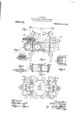
- Fig. 1 is an elevation of the dust guard
- Fig. 2 is a fragmentary, vertical, axial section of a journal box, showing the dust guard well and dust guard, a portion of the axle is also shown in this view.
- Fig. 3 is a horizontal, axial section taken at right angles to the plane of Fig. 2.
- the head ofthe wedge is of slightly greater" dimensions than the Width of lthe slot, so that when the bar is forced down level with the top ofthe box, the opening of the slot is closed and the bar secured therein by friction, forming a plug.
- the screen is suspended transversely of the shaft.
- An opening 11, circular in form and ofV a diameter slightly, perhaps a quarter of an inch, less vthan the diameter of the 4axle at-this point, is formed near the center of the screen.l Surrounding the opening l1,
- the pins 25 extend through the screen and the blocks, one block of the set'13 being secured to two blocks of the s'et 14, and vice
- the continuous, circular frame thus formed of the two sets of blocks is hereinslightly greater ⁇ than the diameter of the axle.
- a portion of the screen extends along theshaft., forming a circular lip 12, which lies between the axle and the bearing member, and is pressed against the formerby the latter.
- the device con-y sists of a continuous screenI of iexible mate. rial inthe form of a'diaphragm closing the end of the box ⁇ ; at its outer edge in close contact with the outer walls of the dust' ard slotz and ⁇ at its inner edge pressed ⁇ tightly against the axle.
- pistons in said should be f 1o d possible to em when these cr y takes place the Ahaust ports, pistons in said follows therefore in its return stroke .l0 that 90% of the considerable co rge clearance space clearance space of the vcyliiint renders it pipes 8 and 9 arranged as to above, which This requireme ploy the cross oss pipes are so form part of the clearance s he arrangement describe simplified by th d is further exe fact that the ranged above the cylintherewith. The hus exceeding] ood thatthe debe considerably.
- inders arranged side ing inletports at its echanicallj operated s leading diagonally opposite ends two steam e by side and ends and separate e/X- arranged to overrun 4and contro-l ysaid eX- haust ports, a -stean'i chest common to said cylindersni mechanically operated admission valves in said chest, two pockets on said chest, the admission of steam to which is controlled by said mechanically operated valves, and connections. leading diagonally from each of said pockets to the diagonally opposite ends of the pair of cylinders.
Landscapes
- Engineering & Computer Science (AREA)
- Mechanical Engineering (AREA)
- Preliminary Treatment Of Fibers (AREA)
Description
J, www. FUB CYLINDER LGMOTIVE ENGNE.. APPLICATION FILED JULY 24, 1909.
Patented Jan. 3, 191.1.
NITE, STATES PATENT oFFioE.
THOMAS H. sYMINGTOr, or BALTIMORE, MAnYLAND, AssrGNoR. TO-'Tnn T. r1. sYMING- TON COMPANY, or BALTrMeRE, MARYLAND, A- CORPORATION or MAINE.
prism-GUARD.
Specification of Letters Patent.
Patented Jan.' 3, 1911.
Application led September 30, 190.8. Serial No. 455,551.
ica, residing at the city of Baltimore, State of Maryland, have invented certain new and useful Improvements in Dust-Guards, of which the following is a specification. 1
The present invention relates to dust guards for journal boxes and contemplates the provision of a new and im )roved device of this character which may e appliedto the various types of journal boxes 'now in use without involving their alteration.
The dust guardisadapted to be placed in the usualdust guard slot and provided with means whereby it is supported therein.
My device consists in a continuous screen of flexible material closing the end of the box and a bearing memberv by which the screen is held in close contact with the axle and the walls of thedust'guard slot. The bearing member is circular in form, inclosing fthe axle, and the upper edge of the screen is provided with a support. This support serves, in? the preferred embodiment of my invention, as a plug to close the well.l
The screen above the axle, between the plug and the bearing member, is made of ample extent, so that it hangs loosely, .as shown.l This permits the box to be raised for the purpose of changing brasses and ,eliminates the necessity of'removing the shaft from 'the box when this operation is to -be performed. Referring to the accompanying drawings,-Figure`1 is an elevation of the dust guard, Fig. 2 is a fragmentary, vertical, axial section of a journal box, showing the dust guard well and dust guard, a portion of the axle is also shown in this view. Fig. 3 is a horizontal, axial section taken at right angles to the plane of Fig. 2.
`The journal box,.a portion' ofy which is shown in'Figse 2 and 3, is provided 'at its inner end with the usual ldust guard slot 2, the vmouth of the slot being at .the top. The lateral walls, 4 andA 5, `of the slot are apertured at 6 and 7 `to'fadmit the axle .8. 4The screenv 9 of heavy, textile material, of vertical and lateral dimensions greater than the corresponding dimensions of the well, isy suspended therein in la plane transverse to the shaft. The support for vthe upper end vof the screen is inthe form of av ar, 10,`of wedge-shaped. cross-section, divided longitudinally to receivethe screen, The head ofthe wedge is of slightly greater" dimensions than the Width of lthe slot, so that when the bar is forced down level with the top ofthe box, the opening of the slot is closed and the bar secured therein by friction, forming a plug. By this means, the screen is suspended transversely of the shaft. An opening 11, circular in form and ofV a diameter slightly, perhaps a quarter of an inch, less vthan the diameter of the 4axle at-this point, is formed near the center of the screen.l Surrounding the opening l1,
' a set of segmental wooden blocks 13 on the inside, i. e. toward the car body, and 14 on the outside, are secured/tothe screen. The
blocks '13 break joints with the blocks 14.
The pins 25 extend through the screen and the blocks, one block of the set'13 being secured to two blocks of the s'et 14, and vice The continuous, circular frame thus formed of the two sets of blocks is hereinslightly greater `than the diameter of the axle. As the opening in the screen is of less diameter than the shaft, and, therefore, less than the opening, a portion of the screen extends along theshaft., forming a circular lip 12, which lies between the axle and the bearing member, and is pressed against the formerby the latter. j g
InP the operation .of thedust guard, the screen and ring are introduced into the slot and placed with .the Opening 11 of the screen in registration with the openings 6 and 7 -of the box, the bar 10 being driven into the mouth of the well. Observing Figs. 2 and 3, it willv be noted that the screen is so supported by the .bearing member that the edges ofthe 'former are 1n contact with the lateral walls of the slot at 15 and 16 and the bottom lwall 17;- The shaft isintroduced into the journal box through the openings 6- andv 7, passing through the a erture 11 1nI the screen, so that it is inclose byithe bearing ring 26. vThe lips 12 are turned inward, between 'the frame and the axle, and'pressed against the latter by the bearing member.
Assembled for operation, the device con-y sists of a continuous screenI of iexible mate. rial inthe form of a'diaphragm closing the end of the box`; at its outer edge in close contact with the outer walls of the dust' ard slotz and `at its inner edge pressed `tightly against the axle. The segmental frame, or
should be f 1o d possible to em when these cr y takes place the Ahaust ports, pistons in said follows therefore in its return stroke .l0 that 90% of the considerable co rge clearance space clearance space of the vcyliiint renders it pipes 8 and 9 arranged as to above, which This requireme ploy the cross oss pipes are so form part of the clearance s he arrangement describe simplified by th d is further exe fact that the ranged above the cylintherewith. The hus exceeding] ood thatthe debe considerably.
ders and is not cas g of the cyli ill be underst tails vof the device kmay isV intended'espeprheated steam but e employed with satulso especially intended ell as high tempera- The engine illustrated or use with su se may also/b rated steam. lIt/'is/a for high pressure as I'claim:- v
1.'In combination, two st inders arranged side ing an inlet port at it haust ports, pistons arranged to earn engine cyle and each havs end and separate exin said cylinders and overrun and control said exa steam chest-common to said controlled by said m valve and connection from said pocket to di oi' 'the pair of cylinde 2. IIn combination, inders arranged side ing inletports at its echanicallj operated s leading diagonally opposite ends two steam e by side and ends and separate e/X- arranged to overrun 4and contro-l ysaid eX- haust ports, a -stean'i chest common to said cylindersni mechanically operated admission valves in said chest, two pockets on said chest, the admission of steam to which is controlled by said mechanically operated valves, and connections. leading diagonally from each of said pockets to the diagonally opposite ends of the pair of cylinders.
` In combination, two steam engine cylinders arrangedfside by side and each having. inlet ports at yits ends and separate exhaust ports, pistons in said cylinders and arrangedto overrun and control said exhaust ports, a common chamber .into which the exhaust ports of both c linders open, a
steam'chest common to sai cylinders, me-
chanically operated admission valves in said chest, two pockets on said chest the admis- "sion of steam to which is controlled by said mechanically operated valves and connections leadin dlagonall from each of said pockets to -te diagona y opposite ends of the pair of c linders.
4. In combination, two steam engine cyl'- inders arranged side by side and each having inlet ports at its ends and separate exhaust ports, pistons in said cylinders and arranged to overrun and control said eX- haust ports, a steam chest common to said cylinders, two mechanically operated lift valves in said chest, two pockets on said chest the admission of steam to -which is lcontrolled by said lit-valves, and connections leadin diagonally from each of Said pockets to te diagonally opposite ends of the pair of cylinders.
In witness whereof I have hereunto .set my hand in the presence of two witnesses.
JOHANN STUMPF.
Witnesses:
AHERMANN BoUrN,
GOTTFRIED KERKAIN,
Priority Applications (1)
| Application Number | Priority Date | Filing Date | Title |
|---|---|---|---|
| US45555108A US980573A (en) | 1908-09-30 | 1908-09-30 | Dust-guard. |
Applications Claiming Priority (1)
| Application Number | Priority Date | Filing Date | Title |
|---|---|---|---|
| US45555108A US980573A (en) | 1908-09-30 | 1908-09-30 | Dust-guard. |
Publications (1)
| Publication Number | Publication Date |
|---|---|
| US980573A true US980573A (en) | 1911-01-03 |
Family
ID=3048944
Family Applications (1)
| Application Number | Title | Priority Date | Filing Date |
|---|---|---|---|
| US45555108A Expired - Lifetime US980573A (en) | 1908-09-30 | 1908-09-30 | Dust-guard. |
Country Status (1)
| Country | Link |
|---|---|
| US (1) | US980573A (en) |
-
1908
- 1908-09-30 US US45555108A patent/US980573A/en not_active Expired - Lifetime
Similar Documents
| Publication | Publication Date | Title |
|---|---|---|
| US980573A (en) | Dust-guard. | |
| US444509A (en) | shar pneck | |
| US905000A (en) | Mine-car pedestal. | |
| US533783A (en) | Steam-engine | |
| US855266A (en) | Automatic stop for pistons. | |
| US934675A (en) | Crank-case for engines. | |
| US905356A (en) | Dust-guard. | |
| US221259A (en) | Improvement in car-axle boxes | |
| US198046A (en) | Improvement in car axle-boxes | |
| US1215192A (en) | Steam-driven air-compressor. | |
| US1095737A (en) | Car-axle box and lid. | |
| US1585700A (en) | Oil trap for rotary engines | |
| US965255A (en) | Metallic rod-packing. | |
| US870001A (en) | Engine. | |
| US850030A (en) | Stamp-shaft tappet. | |
| US153255A (en) | Improvement in car-axle boxes | |
| US870587A (en) | Journal-box. | |
| SU147A1 (en) | Sliding steam valve with pistons sliding on its rolling pin and washers resistant for them | |
| US879606A (en) | Brake mechanism for car-trucks. | |
| US356333A (en) | of new yoek | |
| US1234953A (en) | Journal-bearing. | |
| US578949A (en) | Axle-box | |
| US990057A (en) | Locomotive-valve. | |
| US980572A (en) | Four-cylinder locomotive-engine. | |
| US408880A (en) | Car-axle box |