US9804322B1 - Linear edgelit lighting system with heat sink base and clamp coupled together with a fastener - Google Patents
Linear edgelit lighting system with heat sink base and clamp coupled together with a fastener Download PDFInfo
- Publication number
- US9804322B1 US9804322B1 US14/885,878 US201514885878A US9804322B1 US 9804322 B1 US9804322 B1 US 9804322B1 US 201514885878 A US201514885878 A US 201514885878A US 9804322 B1 US9804322 B1 US 9804322B1
- Authority
- US
- United States
- Prior art keywords
- waveguide
- linear
- heat sink
- edgelit
- lighting device
- Prior art date
- Legal status (The legal status is an assumption and is not a legal conclusion. Google has not performed a legal analysis and makes no representation as to the accuracy of the status listed.)
- Active, expires
Links
Images


Classifications
-
- G—PHYSICS
- G02—OPTICS
- G02B—OPTICAL ELEMENTS, SYSTEMS OR APPARATUS
- G02B6/00—Light guides; Structural details of arrangements comprising light guides and other optical elements, e.g. couplings
- G02B6/0001—Light guides; Structural details of arrangements comprising light guides and other optical elements, e.g. couplings specially adapted for lighting devices or systems
- G02B6/0011—Light guides; Structural details of arrangements comprising light guides and other optical elements, e.g. couplings specially adapted for lighting devices or systems the light guides being planar or of plate-like form
- G02B6/0081—Mechanical or electrical aspects of the light guide and light source in the lighting device peculiar to the adaptation to planar light guides, e.g. concerning packaging
- G02B6/0085—Means for removing heat created by the light source from the package
-
- G—PHYSICS
- G02—OPTICS
- G02B—OPTICAL ELEMENTS, SYSTEMS OR APPARATUS
- G02B6/00—Light guides; Structural details of arrangements comprising light guides and other optical elements, e.g. couplings
- G02B6/0001—Light guides; Structural details of arrangements comprising light guides and other optical elements, e.g. couplings specially adapted for lighting devices or systems
- G02B6/0011—Light guides; Structural details of arrangements comprising light guides and other optical elements, e.g. couplings specially adapted for lighting devices or systems the light guides being planar or of plate-like form
- G02B6/0066—Light guides; Structural details of arrangements comprising light guides and other optical elements, e.g. couplings specially adapted for lighting devices or systems the light guides being planar or of plate-like form characterised by the light source being coupled to the light guide
- G02B6/0068—Arrangements of plural sources, e.g. multi-colour light sources
-
- G—PHYSICS
- G02—OPTICS
- G02B—OPTICAL ELEMENTS, SYSTEMS OR APPARATUS
- G02B6/00—Light guides; Structural details of arrangements comprising light guides and other optical elements, e.g. couplings
- G02B6/0001—Light guides; Structural details of arrangements comprising light guides and other optical elements, e.g. couplings specially adapted for lighting devices or systems
- G02B6/0011—Light guides; Structural details of arrangements comprising light guides and other optical elements, e.g. couplings specially adapted for lighting devices or systems the light guides being planar or of plate-like form
- G02B6/0075—Arrangements of multiple light guides
- G02B6/0078—Side-by-side arrangements, e.g. for large area displays
-
- G—PHYSICS
- G02—OPTICS
- G02B—OPTICAL ELEMENTS, SYSTEMS OR APPARATUS
- G02B6/00—Light guides; Structural details of arrangements comprising light guides and other optical elements, e.g. couplings
- G02B6/0001—Light guides; Structural details of arrangements comprising light guides and other optical elements, e.g. couplings specially adapted for lighting devices or systems
- G02B6/0011—Light guides; Structural details of arrangements comprising light guides and other optical elements, e.g. couplings specially adapted for lighting devices or systems the light guides being planar or of plate-like form
- G02B6/0081—Mechanical or electrical aspects of the light guide and light source in the lighting device peculiar to the adaptation to planar light guides, e.g. concerning packaging
- G02B6/0083—Details of electrical connections of light sources to drivers, circuit boards, or the like
-
- G—PHYSICS
- G02—OPTICS
- G02B—OPTICAL ELEMENTS, SYSTEMS OR APPARATUS
- G02B6/00—Light guides; Structural details of arrangements comprising light guides and other optical elements, e.g. couplings
- G02B6/0001—Light guides; Structural details of arrangements comprising light guides and other optical elements, e.g. couplings specially adapted for lighting devices or systems
- G02B6/0011—Light guides; Structural details of arrangements comprising light guides and other optical elements, e.g. couplings specially adapted for lighting devices or systems the light guides being planar or of plate-like form
- G02B6/0081—Mechanical or electrical aspects of the light guide and light source in the lighting device peculiar to the adaptation to planar light guides, e.g. concerning packaging
- G02B6/0086—Positioning aspects
- G02B6/0088—Positioning aspects of the light guide or other optical sheets in the package
-
- G—PHYSICS
- G02—OPTICS
- G02B—OPTICAL ELEMENTS, SYSTEMS OR APPARATUS
- G02B6/00—Light guides; Structural details of arrangements comprising light guides and other optical elements, e.g. couplings
- G02B6/0001—Light guides; Structural details of arrangements comprising light guides and other optical elements, e.g. couplings specially adapted for lighting devices or systems
- G02B6/0011—Light guides; Structural details of arrangements comprising light guides and other optical elements, e.g. couplings specially adapted for lighting devices or systems the light guides being planar or of plate-like form
- G02B6/0081—Mechanical or electrical aspects of the light guide and light source in the lighting device peculiar to the adaptation to planar light guides, e.g. concerning packaging
- G02B6/0086—Positioning aspects
- G02B6/0091—Positioning aspects of the light source relative to the light guide
-
- F—MECHANICAL ENGINEERING; LIGHTING; HEATING; WEAPONS; BLASTING
- F21—LIGHTING
- F21V—FUNCTIONAL FEATURES OR DETAILS OF LIGHTING DEVICES OR SYSTEMS THEREOF; STRUCTURAL COMBINATIONS OF LIGHTING DEVICES WITH OTHER ARTICLES, NOT OTHERWISE PROVIDED FOR
- F21V7/00—Reflectors for light sources
- F21V7/005—Reflectors for light sources with an elongated shape to cooperate with linear light sources
-
- F—MECHANICAL ENGINEERING; LIGHTING; HEATING; WEAPONS; BLASTING
- F21—LIGHTING
- F21Y—INDEXING SCHEME ASSOCIATED WITH SUBCLASSES F21K, F21L, F21S and F21V, RELATING TO THE FORM OR THE KIND OF THE LIGHT SOURCES OR OF THE COLOUR OF THE LIGHT EMITTED
- F21Y2103/00—Elongate light sources, e.g. fluorescent tubes
- F21Y2103/10—Elongate light sources, e.g. fluorescent tubes comprising a linear array of point-like light-generating elements
-
- F—MECHANICAL ENGINEERING; LIGHTING; HEATING; WEAPONS; BLASTING
- F21—LIGHTING
- F21Y—INDEXING SCHEME ASSOCIATED WITH SUBCLASSES F21K, F21L, F21S and F21V, RELATING TO THE FORM OR THE KIND OF THE LIGHT SOURCES OR OF THE COLOUR OF THE LIGHT EMITTED
- F21Y2115/00—Light-generating elements of semiconductor light sources
- F21Y2115/10—Light-emitting diodes [LED]
-
- G—PHYSICS
- G02—OPTICS
- G02B—OPTICAL ELEMENTS, SYSTEMS OR APPARATUS
- G02B6/00—Light guides; Structural details of arrangements comprising light guides and other optical elements, e.g. couplings
- G02B6/0001—Light guides; Structural details of arrangements comprising light guides and other optical elements, e.g. couplings specially adapted for lighting devices or systems
- G02B6/0011—Light guides; Structural details of arrangements comprising light guides and other optical elements, e.g. couplings specially adapted for lighting devices or systems the light guides being planar or of plate-like form
- G02B6/0033—Means for improving the coupling-out of light from the light guide
- G02B6/005—Means for improving the coupling-out of light from the light guide provided by one optical element, or plurality thereof, placed on the light output side of the light guide
- G02B6/0055—Reflecting element, sheet or layer
Definitions
- Embodiments of the invention relate generally to edgelit lighting fixtures, and in particular, to an edgelit lighting strip that can be linked to one or more other edgelit lighting strips.
- LEDs light emitting diodes
- Edgelit lighting solutions typically include a strip of LEDs and an acrylic lens or waveguide disposed adjacent the LED strip such that the LEDs emit light into the waveguide through an edge of the waveguide. The light then emanates from the surfaces of the waveguide. In some applications, the surfaces of the waveguide include etchings or other features to manipulate the light. Many rooms require lighting that extends linearly across a certain distance. Traditionally, fluorescent lighting elements have been used to provide such lighting. However, given the advantages of LED lighting, it would be beneficial to have an LED based linear lighting solution.
- the present disclosure can relate to a linear edgelit lighting device.
- the linear edgelit lighting device includes a housing channel. Further, the linear edgelit lighting device includes a heat sink assembly coupled to the housing channel.
- the heat sink assembly includes a heat sink base and a heat sink clamp that are coupled together to form a light source housing cavity and a waveguide housing cavity that are located substantially at a middle portion of the heat sink assembly.
- the linear edgelit lighting device includes a waveguide.
- the wave guide includes at least an edge and a plurality of surfaces. The edge is at least partially disposed in the waveguide housing cavity of the heat sink assembly such that the waveguide is substantially perpendicular to the housing channel and/or the heat sink assembly.
- the linear edgelit lighting device includes one or more light emitting diodes (LEDs) disposed within the light source housing cavity of the heat sink assembly and directed towards the edge of the waveguide such that light emitted by the one or more LEDs enter the waveguide through the edge.
- LEDs light emitting diodes
- the heat sink base and the heat sink clamp are coupled together by a fastener disposed at an acute angle relative to the waveguide and offset from the middle portion of the heat sink assembly. Further, the fastener is tightened to pull the heat sink clamp against the heat sink base and to exert an increased horizontal clamping force on the waveguide in order to securely retain the waveguide in the linear edgelit lighting device.
- the present disclosure can relate to a lighting system.
- the lighting system includes a first lighting fixture.
- the first lighting fixture includes a first elongated housing channel having a pair of first open lateral ends. Each first open lateral end is opposite to each other and adjacent a respective lateral edge of the first housing channel. Further, the first lighting fixture includes a pair of first end caps where each first end cap is disposed at a respective first open lateral end to cover the respective first open lateral end.
- the first lighting fixture includes a first light emitting diode (LED) strip that is coupled to the first elongated housing channel. The first LED strip includes a plurality of LEDs.
- LED light emitting diode
- the first lighting fixture may also include a first waveguide that is coupled to the first elongated housing channel such that light emitted from the plurality of LEDs of the first LED strip enters the first waveguide through an edge of the first waveguide.
- the lighting system includes a second lighting fixture.
- the second lighting fixture includes a second housing channel having a pair of second open lateral ends, each second open lateral end being opposite to each other and adjacent a respective lateral edge of the second housing channel.
- the second lighting fixture includes a second light emitting diode (LED) strip coupled to the second elongated housing channel and comprising a plurality of LEDs; and a second waveguide coupled to the second elongated housing channel such that light emitted from the plurality of LEDs of the second LED strip enters the second waveguide through an edge of the second waveguide.
- the first lighting fixture is coupled to the second lighting fixture such that one first open lateral end of the first housing channel is adjacent one second open lateral end of the second housing channel.
- At least one of the pair of first end caps is configured to operate as an alignment bracket to couple the first lighting fixture to the second lighting fixture such that a portion of the at least one of the pair of first end caps is coupled to the first housing channel and another portion of the at least one of the pair of first end caps is coupled to the second housing channel.
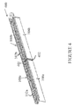
- FIG. 1 illustrates a perspective view of a linear edgelit lighting fixture, in accordance with example embodiments of the present disclosure
- FIG. 2 illustrates a cross-sectional view of the linear edgelit lighting fixture of FIG. 1 , in accordance with example embodiments of the present disclosure
- FIG. 3 illustrates a perspective view of the example of a linear edgelit lighting fixture of FIG. 1 with reflectors, in accordance with example embodiments of the present disclosure
- FIG. 4 illustrates a perspective view of two linear edgelit lighting fixtures linked together, in accordance with example embodiments of the present disclosure
- FIG. 5 illustrates a linear edgelit lighting fixture that includes two waveguides joined together in one housing channel of the linear edgelit lighting fixture, in accordance with example embodiments of the present disclosure
- FIGS. 6A-6D (collectively ‘ FIG. 6 ’) illustrate steps involved in linking together two linear edgelit lighting fixtures, in accordance with example embodiments of the present disclosure
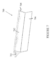
- FIG. 7 illustrates a perspective view of yet another linear edgelit lighting fixture, in accordance with example embodiments of the present disclosure
- FIG. 8 illustrates a top view of the linear edgelit lighting fixture of FIG. 7 , in accordance with example embodiments of the present disclosure
- FIG. 9 illustrates a perspective view of two linear edgelit lighting fixtures linked together, in accordance with example embodiments of the present disclosure.
- FIG. 10 illustrates an open end view of the linear edgelit lighting fixture of FIG. 7 , in accordance with example embodiments of the present disclosure.
- FIG. 11 illustrates a partial view of a linear edgelit lighting fixture having an attached motion sensor, in accordance with example embodiments of the present disclosure.
- FIG. 1 illustrates a perspective view of a linear edgelit lighting fixture 100 .
- FIG. 2 illustrates cross-sectional view of the linear edgelit lighting fixture 100 , in accordance with example embodiments of the present disclosure.
- the linear edgelit lighting fixture 100 (hereinafter ‘lighting fixture 100 ’) includes a housing channel 102 , a heat sink assembly 104 , and an edgelit waveguide 106 .
- the housing channel 102 extends linearly and can be made in a variety of lengths (e.g., 2 feet, 4 feet, 8 feet, etc.).
- the housing channel 102 may be a U-shaped structure that includes a substantially rectangular base portion 190 , and two side walls ( 191 , 192 ), each extending substantially perpendicularly from respective opposite longitudinal edges of the base portion 190 .
- the housing channel 102 has an open side 193 between the two side walls ( 191 , 192 ) and opposite the base portion 190 .
- the housing channel 120 includes two open lateral ends adjacent the opposite lateral edges of the housing channel 102 /base portion 190 of the housing channel 102 (one lateral open end 197 shown in FIG. 2 ).
- end caps 108 may be disposed over the open lateral ends of the housing channel 102 such that they cover the open lateral ends.
- end caps 108 also referred to as channel caps 108 interchangeably throughout this disclosure
- the housing channel 102 may have any other geometric or non-geometric shape without departing from a broader scope of the present disclosure.
- FIGS. 7-10 that will be described in greater detail below illustrates a lighting fixture that has another example housing channel structure.
- the lighting fixture 100 includes a heat sink assembly 104 .
- the heat sink assembly 104 extends along the length of the housing channel 102 .
- the heat sink assembly 104 may be coupled to the side walls ( 191 , 192 ) of the housing channel 102 along the open side 193 of the housing channel 102 opposite the base portion 190 .
- the heat sink assembly 104 may be a two-component construction; however, in other exemplary embodiments, the heat sink assembly 140 is constructed using fewer or greater components.
- the heat sink assembly 104 includes a heat sink base 208 and a heat sink clamp 204 .
- the heat sink base 208 in combination with the heat sink clamp 204 couples the waveguide 106 to the housing channel 102 .
- the heat sink clamp 204 attaches to the heat sink base 208 via a coupling region 210 and a fastener (e.g., screw, rivet, etc.) inserted therein (not shown).
- the heat sink clamp 204 includes a threaded portion 290 that is configured to receive the screw (not shown).
- the threaded portion 290 of the heat sink clamp 204 may be aligned with the coupling portion 209 (e.g., an aperture) of the heat sink base 208 to form the coupling region 210 that is configured to receive a fastener.
- the fastener may pass through the coupling portion 209 of the heat sink base 208 and enter the threaded portion 290 of the heat sink clamp 204 in order to couple the heat sink clamp 204 to the heat sink base 208 .
- the threaded portion 290 may be arranged at an angle, such that when the waveguide 106 is coupled to the housing channel 102 , the fastener that couples the heat sink clamp 204 to the heat sink base 208 may rest at an acute angle with respect to the waveguide 106 offset from a mid-portion of the heat sink assembly 104 .
- the heat sink assembly 104 may include an LED housing cavity 280 and a waveguide housing cavity 270 that extend substantially the length of the housing channel 102 approximately along a middle portion of the heat sink assembly 104 .
- the LED housing cavity 280 and the waveguide housing cavity 270 are formed by coupling the heat sink clamp 204 to the heat sink base 208 using the fastener as described above.
- the LED housing cavity 280 has a greater width than the waveguide housing cavity 270 .
- the width of the LED housing cavity 280 is not greater than the width of the waveguide housing cavity 270 .
- the LED housing cavity 280 is configured to receive one or more LED modules, e.g., LED strips 206 comprising a plurality of LEDs, while the waveguide housing cavity 270 is configured to receive a portion of the waveguide 106 . Further, once a portion of the waveguide 106 is positioned within the waveguide housing cavity 270 , the fastener may be tightened into the threaded portion 290 of the heat sink clamp 204 to pull the heat sink clamp 204 against the heat sink base 208 and exert a horizontal clamping force, due to the acute angle, onto the waveguide 106 . The acute angle of the fastener provides improved retention of the waveguide 106 .
- the waveguide 106 is substantially rectangular shaped and includes a first surface 166 , a second surface 168 facing a direction opposite the first surface 166 , a first longitudinal edge 170 , a second longitudinal edge 172 positioned opposite the first longitudinal edge 170 , a first latitudinal edge 174 disposed between the first surface 166 and the second surface 168 and between the first longitudinal edge 170 and the second longitudinal edge 172 , and a second latitudinal edge 176 positioned opposite the first latitudinal edge 174 and disposed between the first surface 166 and the second surface 168 and between the first longitudinal edge 170 and the second longitudinal edge 172 .
- the waveguide 106 is formed in a different shape that is either geometric or non-geometric in other exemplary embodiments.
- the waveguide 106 is fabricated from an acrylic material and is substantially clear or translucent.
- the waveguide 106 is formed using other suitable materials, such as glass, and can be, or made to be, opaque, if desired.
- At least one of the first surface 166 and the second surface 168 includes features formed into the surfaces 166 , 168 .
- both surfaces 166 , 168 include these features.
- the features are etchings formed into the surfaces 166 , 168 .
- the features are indentations formed using dimples, lasers, or are molded therein. These features facilitate in bringing the light present within the waveguide 106 outside of the waveguide 106 .
- the LED strip 206 is disposed in the LED housing cavity of the heat sink assembly 104 and coupled to the heat sink base 208 in such a way that the LEDs of the LED strip 206 are directed towards an edge (e.g., first longitudinal edge 170 ) of the waveguide 106 retained in the waveguide housing cavity 270 .
- the light emitted from the LEDs of the LED strip 206 enters the waveguide 106 through the first longitudinal edge 170 and is directed towards the second longitudinal edge 172 that faces the area to be illuminated.
- the features facilitate removal of the light from within the waveguide 165 through first and/or second surfaces ( 166 , 168 ) of the waveguide 106 .
- the light emitted through the surfaces ( 166 , 168 ) of the waveguide may be reflected towards an area to be illuminated using one or more reflectors 302 (shown in FIG. 3 ).
- light may also be emitted through the second longitudinal edge 172 that faces the area to be illuminated.
- a cover may be disposed over the second longitudinal edge 172 .
- the LED strip 206 may receive power from an LED driver 202 that is disposed in an enclosed hollow cavity 212 formed by the housing channel 102 , the channel caps 108 , and the heat sink assembly 104 , as illustrated in FIG. 2 .
- the light fixture 100 includes a waveguide cap 110 that covers the lateral ends/latitudinal edges ( 174 , 176 ) of the waveguide 106 .
- the waveguide cap 110 may include a top portion and a bottom portion. The top portion may be shaped substantially similar to the shape of the heat sink assembly 104 such that it covers the heat sink assembly 104 . Further, the bottom portion of the waveguide cap 110 may be shaped substantially similar to the shape of the latitudinal edges of the waveguide such that it covers the lateral ends/latitudinal edges ( 174 , 176 ) of the waveguide 106 .
- the light fixture 100 is configured such that it can be attached end to end with other linear edgelit lighting fixtures 100 , for example at either lateral ends ( 197 ) of the light fixture 100 .
- the channel cap 108 and/or the waveguide cap 110 of the light fixture 100 may be removed.
- each light fixture 300 may have one or more reflectors 302 .
- the light fixture 300 may have two reflectors, one reflector 302 on either side of the housing channel 102 coupled to a bottom portion of the side walls ( 191 , 192 ) of the housing channel 102 or to the heat sink 104 such that they extend at least partially around the waveguide 106 , i.e., facing the respective surfaces 166 , 168 of the waveguide 106 .
- Each reflector 302 may include a reflector interior surface 380 facing one of the surfaces ( 166 , 168 ) of the waveguide 106 and a reflector exterior surface 390 facing away from the surfaces ( 166 , 168 ) of the waveguide 106 .
- the reflector interior surface 380 is fabricated using a reflective material or is fabricated using a non-reflective material and subsequently made to be reflective.
- the reflector interior surface 380 is polished according to some exemplary embodiments or is painted to be made reflective.
- each reflector 302 is oriented with the reflector interior surface 380 facing downwards and towards the surface 166 or 168 of the waveguide.
- the reflector 302 is curved shaped, while in other embodiments; the reflector 302 is substantially planar, or flat-paneled. The shape of the reflector 302 and the features in the waveguide 106 may produce the desired light output.
- FIG. 4 illustrates a perspective view of two linear edgelit lighting fixtures 100 a , 100 b linked together in an assembly 400 , in accordance with example embodiments of the present disclosure.
- the housing channels 102 a , 102 b of the respective light fixtures 100 a , 100 b are joined together at their lateral ends, i.e., the open lateral ends (e.g., open lateral end 197 ) that are configured to receive the channel caps 108 .
- a bridge 401 and waveguide spacer 402 are disposed at the junction of the two waveguides 106 a , 106 b .
- the bridge 401 may be shaped substantially similar to the shape of the heat sink assembly 104 such that the bridge 401 receives and overlaps the heat sink assembly 104 of the first light fixture 100 a on one side and the heat sink assembly 104 of the second light fixture 100 b on an opposite side of the bridge 401 .
- the bridge 401 is configured to bridge/cover the gap between the heat sink assemblies when the first lighting fixture 100 a is coupled to the second lighting fixture 100 b at their lateral ends.
- the waveguide spacer 402 may be shaped substantially similar to the shape of the latitudinal edges of the waveguide 106 and is configured to overlap the respective edges of the two waveguides 106 a , 106 b .
- the waveguide spacer 402 may be configured to receive and secure a latitudinal edge 176 , 178 of a first waveguide 106 a on a first side of the waveguide spacer 402 and receive and secure a latitudinal edge 176 , 178 of the second waveguide 106 b on a second side of the waveguide spacer 402 , to join and align the waveguides 106 a , 106 b together and cover a gap formed between the waveguides 106 a , 106 b when the first light fixture 100 a is coupled to the second light fixture 100 b .
- the bridge 401 and/or the waveguide spacer 402 may be fully opaque, partially opaque, or clear.
- the bridge 401 and/or the waveguide spacer 402 may be formed using polymer material; however, in other example embodiments, any other appropriate material may be used without departing from a broader scope of the present disclosure.
- FIG. 5 illustrates a linear edgelit lighting fixture 500 with one integral housing channel 502 and two waveguides 106 a , 106 b joined together, in accordance with example embodiments of the present disclosure.
- the two waveguides 106 a , 106 b are both coupled to the same housing channel 502 which extends across the combined length of the two waveguides 106 a , 106 b .
- the linear edgelit lighting fixture 500 includes a bridge 401 and a waveguide spacer 402 that link the two waveguides 106 a , 106 b together.
- a housing channel 102 of the first lighting fixture 100 a may include one or more aligner slots 604 , alignment apertures 603 , and coupling apertures 608 located on the base portion 190 of the housing channel 102 .
- the housing channel 102 may include two aligner slots 604 that may be located close to the open lateral end 601 of the first lighting fixture 100 a .
- the alignment aperture 603 and the coupling aperture 608 may also be located at a close proximity of the open lateral end 601 .
- the aligner slots 604 may be parallel to each other, and spaced apart from each other, as illustrated in FIG. 6A .
- a substantially L-shaped flange 605 which extends substantially perpendicular to the base portion 190 of the housing channel 102 may be located adjacent each aligner slot 604 (e.g., extends from an edge of the aligner slot 604 ), as illustrated in FIG. 6A .
- the substantially L-shaped flanges 605 may extend is a direction towards the open side 193 (or towards heat sink assembly 104 ) of the housing channel 102 and may be configured to face each other.
- each substantially L-shaped flange 605 may include (i) a first leg 691 that is perpendicular to the base portion 190 of the housing channel 102 a and (ii) a second leg 692 that extends from an end of the first leg 691 and is substantially perpendicular to the first leg 691 and parallel to the base portion 190 .
- the housing channel may have flanges of any other appropriate shape without departing from a broader scope of the present disclosure.
- the flange 605 may have a curved or hook-like shape.
- the L-shaped flanges 605 may be configured to receive and support an aligner bracket 602 .
- the aligner bracket 602 may include a substantially rectangular shaped top plate 660 , and a flange 662 extending substantially perpendicularly from a mid-portion of either lateral ends of the top plate 660 .
- the top plate 660 of the aligner bracket 602 may have an elongated slot or aperture 607 , and one or more alignment features 606 (such as a formed dimple, embossed dip, etc.), each adjacent to the opposite flanges 662 .
- each flange 662 may include one or more apertures (or screw bosses), as illustrated in FIG. 6B .
- the aligner bracket 602 is an example and is not limiting. That is, the aligner bracket 602 can have any other appropriate shape without departing from a broader scope of the present disclosure.
- a portion of the aligner bracket 602 (e.g., longitudinal edges and a corresponding portion of the aligner bracket 602 ) may be inserted into the L-shaped flanges 605 such that when fully inserted, the alignment feature 606 (e.g., embossed dip, formed dimple, etc.) of the aligner bracket 602 engages the alignment aperture 603 of the housing channel's base portion 190 to align and lock the aligner bracket 602 in place. Further, when the aligner bracket 602 is locked in place, the coupling aperture 607 of the aligner bracket 602 may be aligned with the coupling aperture 608 of the housing channel 102 a .
- the alignment feature 606 e.g., embossed dip, formed dimple, etc.
- the second leg of the L-shaped flanges 605 that is substantially parallel to the base portion 190 of the housing channel 102 a receives and supports the top plate 660 of the aligner bracket 602 .
- the aligner bracket 602 is secured to the first housing channel 102 a using a coupling member (also referred to as ‘linking fastener’), such as a screw, rivet, etc., which is inserted through the aligned coupling aperture 607 of the aligner bracket 602 and the coupling aperture 608 of the housing channel's base portion 190 .
- a coupling member also referred to as ‘linking fastener’
- linking fastener such as a screw, rivet, etc.
- the aligner bracket 602 is the same item as the channel cap 108 shown in FIG. 1 , which is removed from its position, re-oriented appropriately, and inserted into the L-shaped flanges 605 of the housing channel 102 a as shown in FIG. 6B . Accordingly, the apertures/screw bosses on each flange 662 of the aligner bracket 602 is functional to couple the aligner bracket 602 to the side walls ( 191 , 192 ) of the housing channel 102 a when the aligner bracket 602 is used as a channel cap 108 to cover the open lateral end 601 of the housing channel 102 a .
- aligner bracket 602 is the same item as the channel cap 108
- aligner bracket 602 and the channel cap 108 may be different items that may or may not have the same shape and/or size without departing from a broader scope of the present disclosure.
- the bridge 401 and spacer 402 are added onto the open lateral end 601 of the first housing channel 102 a and/or the waveguide 106 a .
- the second lighting fixture 100 b is joined adjacently to the open lateral end 601 of the first lighting fixture 100 a via the aligner bracket 602 , the bridge 401 , and the spacer 402 .
- FIG. 6D illustrates that the aligner bracket 602 , the bridge 401 , and the spacer 402 .
- the aligner bracket 602 may extend past the first housing channel 102 a , i.e., outside of the first housing channel 102 a through the open lateral end 601 .
- the aligner bracket 602 may be received by the L-shaped flanges 605 , one of the aligner flanges 662 rests within the housing channel 102 a , while the other aligner flange 662 that extends from the opposite lateral end of the aligner bracket 602 remain outside the housing channel 102 .
- the extending end of the aligner bracket 602 is inserted into substantially L-shaped flanges 605 in the second housing channel 102 b of the second lighting fixture 100 b , such that the alignment feature 606 adjacent the second flange 662 of the extending aligner bracket portion engages the alignment aperture 603 of the second housing channel 102 b .
- a linking fastener may be inserted through the aligned other coupling aperture 607 of the aligner bracket 602 and the coupling aperture 608 of the second housing channel 102 b to couple the aligner bracket 602 to the second lighting fixture 100 b .
- the second housing channel 102 b and second waveguide 106 b are coupled to the bridge 401 and spacer 402 adjacent to the first housing channel 102 a and/or first waveguide 106 a.
- linear edgelit lighting fixtures 100 when two or more linear edgelit lighting fixtures 100 are joined together, they may be electrically wired together such that one power supply can supply power to all of the linear edgelit lighting fixtures 100 .
- one driver may be coupled to the power supply and the one driver may power each of the linked lighting fixtures.
- the driver may be internal to the housing channel or external to the lighting fixture.
- the linear edgelit lighting fixtures 100 are wired separately and have individual power supplies.
- FIGS. 7-10 illustrate different views of another linear edgelit lighting fixture 700 , in accordance with example embodiments of the present disclosure.
- FIG. 7 illustrates a perspective view of yet another linear edgelit lighting fixture, in accordance with example embodiments of the present disclosure
- FIG. 8 illustrates a top view of the linear edgelit lighting fixture of FIG. 7 , in accordance with example embodiments of the present disclosure
- FIG. 9 illustrates a perspective view of two linear edgelit lighting fixtures linked together, in accordance with example embodiments of the present disclosure
- FIG. 10 illustrates an open end view of the linear edgelit lighting fixture of FIG. 7 , in accordance with example embodiments of the present disclosure.
- the lighting fixture 700 includes a housing channel 702 , an edgelit waveguide 706 , and endcaps 704 .
- the housing channel 702 may have a tapered linear shape. That is, the housing channel 102 may be a substantially V-shaped structure that includes a first half member 702 a and a second half member 702 b that join to form the housing channel 702 .
- the housing channel 702 may include a top surface 802 coupled to first and second half members 702 a , 702 b .
- the top surface 802 may include a plurality of mounting features, such as surface mounting features, pendant mounting features, cable mounting features, and continuous row mounting features, and so on.
- the first half member 702 a , the second half member 702 b , and the top surface 802 in combination may form a V-shaped cavity inside the housing channel 702 to house one or more electronic components associated with the lighting fixtures, e.g., driver 1004 .
- the half members 702 a , 702 b are placed together such that a coupling clamp feature 1009 (a threaded region) of the first half member 702 a is aligned with a coupling aperture of the second half member 702 b to receive a fastener, such as a screw 1010 to join the two half members 702 a , 702 b .
- a coupling clamp feature 1009 a threaded region
- a fastener such as a screw 1010
- the waveguide housing cavity is a space between the first half member 702 a and the second half member 702 b of the housing cavity located at a bottom portion of the housing channel 702 , i.e., the narrow end of the V-shaped structure.
- the lighting fixture 700 further includes an LED strip 1008 disposed in the LED housing cavity and coupled to a bottom portion of the coupling clamp feature 1009 away from the fastener.
- the LED strip may be disposed above and directed towards an edge (e.g., longitudinal edge) of the waveguide 706 . Light from the LEDs that enter the edge of the waveguide 706 may exit the waveguide through the major surfaces of the waveguide as described above in association with FIGS. 1-2 .
- the lighting fixture 700 includes, inter alia, an end bracket 1002 , hanger pins 1012 , and a surface mounting channel 1006 .
- the lighting fixture 700 may be linked to one or more other lighting fixtures 700 to form an assembly 900 .
- the assembly 900 may include spacer 902 , 904 that snaps in place and is disposed between the first and second waveguides 706 a , 706 b , and between the first and second housing channels 702 a , 702 b of the first lighting fixture 700 a and the second lighting fixture 700 b .
- the spacer 902 , 904 may reduce/remove a gap formed between the first and second waveguides 706 a , 706 b and the first and second housing channels 702 a , 702 b when the first lighting fixture 700 a is coupled to the second lighting fixture 700 b as described above in association with FIGS. 4-6 .
- FIG. 11 this figure illustrates a partial view of a lighting fixture 1100 having an attached motion sensor 1102 , in accordance with example embodiments of the present disclosure.
- a motion sensor 1102 is attached to the end of the housing channel 102 via a sensor bracket 1106 .
- the motion sensor 1102 is attached to a motion sensor housing 1104 which is coupled to the housing channel 102 via the sensor bracket 1106 .
- the sensor bracket 1106 is disposed above the housing channel 102 of the lighting fixture and the sensor housing 1104 such that a portion of the housing channel 102 and a portion of the sensor housing 1104 that is adjacent to each other is disposed within and coupled to the sensor bracket 1106 .
- the sensor housing 1104 may be coupled to the lighting fixture 1100 using any other coupling mechanism without departing from a broader scope of the present disclosure.
- FIG. 11 illustrates an elongated U-shaped sensor bracket 1106
- the sensor bracket 1106 can have any other appropriate shape without departing from a broader scope of the present disclosure.
- the present disclosure describes the sensor coupled to the lighting fixture as a motion sensor, one of ordinary skill in the art can understand and appreciate that any other appropriate electronic component or sensor (e.g., daylight sensor, occupancy sensor, etc.) can be coupled to the lighting fixture instead of or in addition to the motion sensor without departing from a broader scope of the present disclosure.
- the sensor 1102 can be positioned at any appropriate place along the lighting fixture and/or the sensor bracket without departing from a broader scope of the present disclosure.
Landscapes
- Physics & Mathematics (AREA)
- General Physics & Mathematics (AREA)
- Optics & Photonics (AREA)
- Non-Portable Lighting Devices Or Systems Thereof (AREA)
Abstract
Description
Claims (20)
Priority Applications (1)
| Application Number | Priority Date | Filing Date | Title |
|---|---|---|---|
| US14/885,878 US9804322B1 (en) | 2014-10-21 | 2015-10-16 | Linear edgelit lighting system with heat sink base and clamp coupled together with a fastener |
Applications Claiming Priority (2)
| Application Number | Priority Date | Filing Date | Title |
|---|---|---|---|
| US201462066589P | 2014-10-21 | 2014-10-21 | |
| US14/885,878 US9804322B1 (en) | 2014-10-21 | 2015-10-16 | Linear edgelit lighting system with heat sink base and clamp coupled together with a fastener |
Publications (1)
| Publication Number | Publication Date |
|---|---|
| US9804322B1 true US9804322B1 (en) | 2017-10-31 |
Family
ID=60142570
Family Applications (1)
| Application Number | Title | Priority Date | Filing Date |
|---|---|---|---|
| US14/885,878 Active 2035-11-26 US9804322B1 (en) | 2014-10-21 | 2015-10-16 | Linear edgelit lighting system with heat sink base and clamp coupled together with a fastener |
Country Status (1)
| Country | Link |
|---|---|
| US (1) | US9804322B1 (en) |
Cited By (2)
| Publication number | Priority date | Publication date | Assignee | Title |
|---|---|---|---|---|
| US20180286295A1 (en) * | 2017-03-28 | 2018-10-04 | GE Lighting Solutions, LLC | Light emitting diode assembly |
| US10802765B2 (en) | 2016-04-26 | 2020-10-13 | Servicenow, Inc. | Detection and remediation of memory leaks |
Citations (52)
| Publication number | Priority date | Publication date | Assignee | Title |
|---|---|---|---|---|
| USD374301S (en) | 1994-09-06 | 1996-10-01 | Kleffman Gene A | Fluorescent light fixture |
| USD386804S (en) | 1995-04-03 | 1997-11-25 | Luederlitz Licht GmbH | Light fixture |
| US5988836A (en) | 1996-07-31 | 1999-11-23 | Swarens; Ralph W. | Recessed indirect fluorescent light fixture with flexible reflector |
| CN1371018A (en) | 2001-02-20 | 2002-09-25 | 达碁科技股份有限公司 | Frame for fixing light guide plate and backlight device thereof |
| USD477891S1 (en) | 2001-02-09 | 2003-07-29 | Zumtobel Staff Gmbh | Ceiling light |
| USD496121S1 (en) | 2004-02-03 | 2004-09-14 | Ledalite Architectural Products | Recessed fluorescent luminaire |
| US20080055534A1 (en) | 2006-08-30 | 2008-03-06 | Nec Lcd Technologies, Ltd. | Back light unit and liquid crystal display device using the same |
| US20090103327A1 (en) | 2007-10-19 | 2009-04-23 | Fujifilm Corporation | Light guide plate |
| USD593246S1 (en) | 2008-08-29 | 2009-05-26 | Hubbell Incorporated | Full distribution troffer luminaire |
| USD595006S1 (en) | 2005-11-22 | 2009-06-23 | Ledalite Architectural Products | Recessed fluorescent luminaire |
| USD608932S1 (en) | 2009-04-17 | 2010-01-26 | Michael Castelli | Light fixture |
| US20100165662A1 (en) | 2007-06-12 | 2010-07-01 | Tetsuya Hamada | Backlight unit |
| US20100271841A1 (en) | 2009-04-27 | 2010-10-28 | Led Folio Corporation | LED Lighting With Light Guide Plate Having Side Reflector |
| USD633247S1 (en) | 2009-06-15 | 2011-02-22 | Lg Innotek Co., Ltd. | Light-emitting diode (LED) interior light |
| US20110176306A1 (en) | 2009-08-19 | 2011-07-21 | Kwang Soo Kim | Lighting Device |
| USD653376S1 (en) | 2009-08-25 | 2012-01-31 | Lg Innotek Co., Ltd. | Light-emitting diode (LED) interior lights fixture |
| WO2012030387A2 (en) | 2010-08-31 | 2012-03-08 | Cree, Inc. | Troffer-style fixture |
| US20120169967A1 (en) | 2011-01-03 | 2012-07-05 | Lg Display Co., Ltd. | Two-Way Liquid Crystal Display Device |
| US20120182713A1 (en) | 2011-01-14 | 2012-07-19 | Eric Bretschneider | Lighting unit with light emitting elements |
| US8232724B2 (en) | 2009-02-06 | 2012-07-31 | Tyco Electronics Corporation | End cap assembly for a light tube |
| USD664699S1 (en) | 2011-04-13 | 2012-07-31 | Mitsubishi Electric Corporation | Lighting apparatus for elevator |
| USD665119S1 (en) | 2011-07-21 | 2012-08-07 | Cooper Technologies Company | Troffer luminaire |
| USD667983S1 (en) | 2011-03-09 | 2012-09-25 | Cree, Inc. | Troffer-style lighting fixture |
| USD672079S1 (en) | 2010-03-25 | 2012-12-04 | Lg Innotek Co., Ltd. | LED light |
| USD673711S1 (en) | 2011-03-09 | 2013-01-01 | Cree, Inc. | Troffer-style lighting fixture |
| USD675364S1 (en) | 2012-05-03 | 2013-01-29 | Focal Point, L.L.C. | Lighting fixture |
| US20130051067A1 (en) | 2011-08-30 | 2013-02-28 | Kocam International Co., Ltd. | Backlight Module with Connecting Circuits |
| USD677820S1 (en) | 2012-05-04 | 2013-03-12 | Abl Ip Holding Llc | Light fixture |
| USD678597S1 (en) | 2010-11-08 | 2013-03-19 | Cooper Technologies Company | Troffer with lens |
| USD681872S1 (en) | 2010-03-25 | 2013-05-07 | Lg Innotek Co., Ltd. | Frame for a ceiling light |
| USD685942S1 (en) | 2011-10-11 | 2013-07-09 | Koninklijke Philips Electronics N.V. | LED module |
| US20130194820A1 (en) | 2012-01-26 | 2013-08-01 | Cree, Inc. | Reduced contrast led lighting system |
| US20130208457A1 (en) | 2012-02-09 | 2013-08-15 | Cree, Inc. | Troffer-style lighting fixture with specular reflector |
| US20130294053A1 (en) | 2012-05-07 | 2013-11-07 | Abl Ip Holding Llc | Led light fixture |
| US20130307420A1 (en) | 2012-05-17 | 2013-11-21 | Benjamin Lee Yoder | Edge lit luminaires for windows |
| USD696449S1 (en) | 2013-03-14 | 2013-12-24 | Lsi Industries, Inc. | Lighting |
| USD698975S1 (en) | 2013-04-22 | 2014-02-04 | Cooper Technologies Company | Edgelit blade luminaire |
| USD698969S1 (en) | 2012-02-23 | 2014-02-04 | Koninklijke Philips N.V. | Ceiling lamp |
| USD698973S1 (en) | 2012-12-24 | 2014-02-04 | Fluxwerx Illumination Inc. | Luminaire |
| US20140036533A1 (en) | 2012-08-01 | 2014-02-06 | E3 Displays, Llc | Dual mode lcd backlight |
| USD699386S1 (en) | 2013-04-09 | 2014-02-11 | Posco Led Company Ltd. | Diffusive flood light plate for lighting apparatus |
| USD701988S1 (en) | 2013-04-22 | 2014-04-01 | Cooper Technologies Company | Multi-panel edgelit luminaire |
| USD705474S1 (en) | 2012-10-24 | 2014-05-20 | Zumtobel Lighting Gmbh | Luminaire |
| US20140192558A1 (en) * | 2012-09-13 | 2014-07-10 | Quarkstar Llc | Illumination Systems Providing Direct and Indirect Illumination |
| US20140198481A1 (en) | 2011-08-22 | 2014-07-17 | Jin Wook Kim | Lighting device |
| US20140268869A1 (en) | 2013-03-15 | 2014-09-18 | James H. Blessitt | Edgelit LED Blade Fixture |
| USD714988S1 (en) | 2013-04-09 | 2014-10-07 | Posco Led Company Ltd. | Ceiling-buried type luminaire |
| US20150049511A1 (en) * | 2013-03-15 | 2015-02-19 | Cree, Inc. | Waveguide Having Unidirectional Illuminance |
| US9046225B2 (en) * | 2013-08-16 | 2015-06-02 | General Electric Company | Lighting system with improved illumination distribution |
| USD735391S1 (en) | 2014-02-25 | 2015-07-28 | Cooper Technologies Company | Edge-lit blade luminaire |
| US9127826B2 (en) | 2013-03-14 | 2015-09-08 | Lsi Industries, Inc. | Indirect lighting luminaire |
| US9182534B2 (en) * | 2011-06-07 | 2015-11-10 | Sharp Kabushiki Kaisha | Display device and television receiver |
-
2015
- 2015-10-16 US US14/885,878 patent/US9804322B1/en active Active
Patent Citations (57)
| Publication number | Priority date | Publication date | Assignee | Title |
|---|---|---|---|---|
| USD374301S (en) | 1994-09-06 | 1996-10-01 | Kleffman Gene A | Fluorescent light fixture |
| USD386804S (en) | 1995-04-03 | 1997-11-25 | Luederlitz Licht GmbH | Light fixture |
| US5988836A (en) | 1996-07-31 | 1999-11-23 | Swarens; Ralph W. | Recessed indirect fluorescent light fixture with flexible reflector |
| USD477891S1 (en) | 2001-02-09 | 2003-07-29 | Zumtobel Staff Gmbh | Ceiling light |
| CN1371018A (en) | 2001-02-20 | 2002-09-25 | 达碁科技股份有限公司 | Frame for fixing light guide plate and backlight device thereof |
| USD496121S1 (en) | 2004-02-03 | 2004-09-14 | Ledalite Architectural Products | Recessed fluorescent luminaire |
| USD595006S1 (en) | 2005-11-22 | 2009-06-23 | Ledalite Architectural Products | Recessed fluorescent luminaire |
| US20080055534A1 (en) | 2006-08-30 | 2008-03-06 | Nec Lcd Technologies, Ltd. | Back light unit and liquid crystal display device using the same |
| US20100165662A1 (en) | 2007-06-12 | 2010-07-01 | Tetsuya Hamada | Backlight unit |
| US20090103327A1 (en) | 2007-10-19 | 2009-04-23 | Fujifilm Corporation | Light guide plate |
| USD593246S1 (en) | 2008-08-29 | 2009-05-26 | Hubbell Incorporated | Full distribution troffer luminaire |
| USD604000S1 (en) | 2008-08-29 | 2009-11-10 | Hubbell Incorporated | Full distribution troffer luminaire |
| US8232724B2 (en) | 2009-02-06 | 2012-07-31 | Tyco Electronics Corporation | End cap assembly for a light tube |
| USD608932S1 (en) | 2009-04-17 | 2010-01-26 | Michael Castelli | Light fixture |
| US20100271841A1 (en) | 2009-04-27 | 2010-10-28 | Led Folio Corporation | LED Lighting With Light Guide Plate Having Side Reflector |
| USD633247S1 (en) | 2009-06-15 | 2011-02-22 | Lg Innotek Co., Ltd. | Light-emitting diode (LED) interior light |
| US20110176306A1 (en) | 2009-08-19 | 2011-07-21 | Kwang Soo Kim | Lighting Device |
| US8128256B2 (en) | 2009-08-19 | 2012-03-06 | Lg Innotek Co., Ltd. | Lighting device |
| USD653376S1 (en) | 2009-08-25 | 2012-01-31 | Lg Innotek Co., Ltd. | Light-emitting diode (LED) interior lights fixture |
| USD681872S1 (en) | 2010-03-25 | 2013-05-07 | Lg Innotek Co., Ltd. | Frame for a ceiling light |
| USD672079S1 (en) | 2010-03-25 | 2012-12-04 | Lg Innotek Co., Ltd. | LED light |
| WO2012030387A2 (en) | 2010-08-31 | 2012-03-08 | Cree, Inc. | Troffer-style fixture |
| USD678597S1 (en) | 2010-11-08 | 2013-03-19 | Cooper Technologies Company | Troffer with lens |
| US20120169967A1 (en) | 2011-01-03 | 2012-07-05 | Lg Display Co., Ltd. | Two-Way Liquid Crystal Display Device |
| US20120182713A1 (en) | 2011-01-14 | 2012-07-19 | Eric Bretschneider | Lighting unit with light emitting elements |
| USD667983S1 (en) | 2011-03-09 | 2012-09-25 | Cree, Inc. | Troffer-style lighting fixture |
| USD673711S1 (en) | 2011-03-09 | 2013-01-01 | Cree, Inc. | Troffer-style lighting fixture |
| USD664699S1 (en) | 2011-04-13 | 2012-07-31 | Mitsubishi Electric Corporation | Lighting apparatus for elevator |
| US9182534B2 (en) * | 2011-06-07 | 2015-11-10 | Sharp Kabushiki Kaisha | Display device and television receiver |
| USD665119S1 (en) | 2011-07-21 | 2012-08-07 | Cooper Technologies Company | Troffer luminaire |
| US20140198481A1 (en) | 2011-08-22 | 2014-07-17 | Jin Wook Kim | Lighting device |
| US20130051067A1 (en) | 2011-08-30 | 2013-02-28 | Kocam International Co., Ltd. | Backlight Module with Connecting Circuits |
| USD685942S1 (en) | 2011-10-11 | 2013-07-09 | Koninklijke Philips Electronics N.V. | LED module |
| US20130194820A1 (en) | 2012-01-26 | 2013-08-01 | Cree, Inc. | Reduced contrast led lighting system |
| US20130208457A1 (en) | 2012-02-09 | 2013-08-15 | Cree, Inc. | Troffer-style lighting fixture with specular reflector |
| USD698969S1 (en) | 2012-02-23 | 2014-02-04 | Koninklijke Philips N.V. | Ceiling lamp |
| USD675364S1 (en) | 2012-05-03 | 2013-01-29 | Focal Point, L.L.C. | Lighting fixture |
| USD677820S1 (en) | 2012-05-04 | 2013-03-12 | Abl Ip Holding Llc | Light fixture |
| US20130294053A1 (en) | 2012-05-07 | 2013-11-07 | Abl Ip Holding Llc | Led light fixture |
| US20130307420A1 (en) | 2012-05-17 | 2013-11-21 | Benjamin Lee Yoder | Edge lit luminaires for windows |
| US20140036533A1 (en) | 2012-08-01 | 2014-02-06 | E3 Displays, Llc | Dual mode lcd backlight |
| US20140192558A1 (en) * | 2012-09-13 | 2014-07-10 | Quarkstar Llc | Illumination Systems Providing Direct and Indirect Illumination |
| USD705474S1 (en) | 2012-10-24 | 2014-05-20 | Zumtobel Lighting Gmbh | Luminaire |
| USD698973S1 (en) | 2012-12-24 | 2014-02-04 | Fluxwerx Illumination Inc. | Luminaire |
| USD739977S1 (en) | 2013-03-14 | 2015-09-29 | Lsi Industries, Inc. | Lighting |
| US9127826B2 (en) | 2013-03-14 | 2015-09-08 | Lsi Industries, Inc. | Indirect lighting luminaire |
| USD707873S1 (en) | 2013-03-14 | 2014-06-24 | Lsi Industries, Inc. | Lighting |
| USD696449S1 (en) | 2013-03-14 | 2013-12-24 | Lsi Industries, Inc. | Lighting |
| US20150049511A1 (en) * | 2013-03-15 | 2015-02-19 | Cree, Inc. | Waveguide Having Unidirectional Illuminance |
| US20140268869A1 (en) | 2013-03-15 | 2014-09-18 | James H. Blessitt | Edgelit LED Blade Fixture |
| USD699386S1 (en) | 2013-04-09 | 2014-02-11 | Posco Led Company Ltd. | Diffusive flood light plate for lighting apparatus |
| USD714988S1 (en) | 2013-04-09 | 2014-10-07 | Posco Led Company Ltd. | Ceiling-buried type luminaire |
| USD705974S1 (en) | 2013-04-22 | 2014-05-27 | Cooper Technologies Company | Edgelit blade luminaire |
| USD701988S1 (en) | 2013-04-22 | 2014-04-01 | Cooper Technologies Company | Multi-panel edgelit luminaire |
| USD698975S1 (en) | 2013-04-22 | 2014-02-04 | Cooper Technologies Company | Edgelit blade luminaire |
| US9046225B2 (en) * | 2013-08-16 | 2015-06-02 | General Electric Company | Lighting system with improved illumination distribution |
| USD735391S1 (en) | 2014-02-25 | 2015-07-28 | Cooper Technologies Company | Edge-lit blade luminaire |
Non-Patent Citations (2)
| Title |
|---|
| Cooper Lighting, Skyridge 1×4, 1×2 PAR Graphic Documentation; Nov. 14, 2013. |
| International Search Report for PCT/US2014/026500, dated Aug. 7, 2014. |
Cited By (3)
| Publication number | Priority date | Publication date | Assignee | Title |
|---|---|---|---|---|
| US10802765B2 (en) | 2016-04-26 | 2020-10-13 | Servicenow, Inc. | Detection and remediation of memory leaks |
| US11455125B2 (en) | 2016-04-26 | 2022-09-27 | Servicenow, Inc. | Detection and remediation of memory leaks |
| US20180286295A1 (en) * | 2017-03-28 | 2018-10-04 | GE Lighting Solutions, LLC | Light emitting diode assembly |
Similar Documents
| Publication | Publication Date | Title |
|---|---|---|
| US10113715B2 (en) | Shevle system and label LED strip lamp therefor | |
| US8083375B2 (en) | Lamp device | |
| US20130336008A1 (en) | Lighting Device | |
| US11131443B2 (en) | Horizontal light guide based lighting fixture | |
| US10156330B2 (en) | LED ceiling lamp | |
| JP2013038078A (en) | Led lighting lamp | |
| CN103363448A (en) | Light guide element, lighting module and panel lamp | |
| KR101501713B1 (en) | Led lighting apparatus | |
| ATE259044T1 (en) | REFLECTOR LAMP, ESPECIALLY FLOOR, CEILING OR WALL RECESSED REFLECTOR LAMP | |
| US20180149320A1 (en) | Light-emitting diode type lighting device | |
| CN103026124A (en) | Embedded illumination structure | |
| US9804322B1 (en) | Linear edgelit lighting system with heat sink base and clamp coupled together with a fastener | |
| US8944666B2 (en) | Lighting device | |
| JP2019533280A (en) | Interconnectable light guide tiles | |
| KR101478628B1 (en) | Body of Light Emitting Diode Lamp | |
| TWI629434B (en) | Lamp device | |
| JP2014167850A (en) | Lighting device | |
| KR200456372Y1 (en) | Frame for covering Lighting instruments | |
| CN217714658U (en) | Lamp assembly and lighting lamp with same | |
| CN105465662B (en) | A kind of linear modulation | |
| KR101442804B1 (en) | LED lamp | |
| KR101545689B1 (en) | LED Lighting Apparatus | |
| KR101665487B1 (en) | Wire fixing stopperof lighting | |
| KR101462511B1 (en) | Led lens and light source module with led lens | |
| TWM451475U (en) | Frame of illumination apparatus |
Legal Events
| Date | Code | Title | Description |
|---|---|---|---|
| AS | Assignment |
Owner name: COOPER TECHNOLOGIES COMPANY, TEXAS Free format text: ASSIGNMENT OF ASSIGNORS INTEREST;ASSIGNORS:BLESSITT, JAMES;LADEWIG, CHRISTOPHER;REEL/FRAME:037542/0426 Effective date: 20151015 |
|
| STCF | Information on status: patent grant |
Free format text: PATENTED CASE |
|
| AS | Assignment |
Owner name: EATON INTELLIGENT POWER LIMITED, IRELAND Free format text: ASSIGNMENT OF ASSIGNORS INTEREST;ASSIGNOR:COOPER TECHNOLOGIES COMPANY;REEL/FRAME:048207/0819 Effective date: 20171231 |
|
| AS | Assignment |
Owner name: EATON INTELLIGENT POWER LIMITED, IRELAND Free format text: CORRECTIVE ASSIGNMENT TO CORRECT THE COVER SHEET TO REMOVE APPLICATION NO. 15567271 PREVIOUSLY RECORDED ON REEL 048207 FRAME 0819. ASSIGNOR(S) HEREBY CONFIRMS THE ASSIGNMENT;ASSIGNOR:COOPER TECHNOLOGIES COMPANY;REEL/FRAME:048655/0114 Effective date: 20171231 |
|
| AS | Assignment |
Owner name: SIGNIFY HOLDING B.V., NETHERLANDS Free format text: ASSIGNMENT OF ASSIGNORS INTEREST;ASSIGNOR:EATON INTELLIGENT POWER LIMITED;REEL/FRAME:052681/0475 Effective date: 20200302 |
|
| AS | Assignment |
Owner name: SIGNIFY HOLDING B.V., NETHERLANDS Free format text: CORRECTIVE ASSIGNMENT TO CORRECT THE APPLICATION NUMBERS 12183490, 12183499, 12494944, 12961315, 13528561, 13600790, 13826197, 14605880, 15186648, RECORDED IN ERROR PREVIOUSLY RECORDED ON REEL 052681 FRAME 0475. ASSIGNOR(S) HEREBY CONFIRMS THE ASSIGNMENT;ASSIGNOR:EATON INTELLIGENT POWER LIMITED;REEL/FRAME:055965/0721 Effective date: 20200302 |
|
| MAFP | Maintenance fee payment |
Free format text: PAYMENT OF MAINTENANCE FEE, 4TH YEAR, LARGE ENTITY (ORIGINAL EVENT CODE: M1551); ENTITY STATUS OF PATENT OWNER: LARGE ENTITY Year of fee payment: 4 |
|
| MAFP | Maintenance fee payment |
Free format text: PAYMENT OF MAINTENANCE FEE, 8TH YEAR, LARGE ENTITY (ORIGINAL EVENT CODE: M1552); ENTITY STATUS OF PATENT OWNER: LARGE ENTITY Year of fee payment: 8 |