US9801245B2 - Light fixture - Google Patents
Light fixture Download PDFInfo
- Publication number
- US9801245B2 US9801245B2 US15/213,779 US201615213779A US9801245B2 US 9801245 B2 US9801245 B2 US 9801245B2 US 201615213779 A US201615213779 A US 201615213779A US 9801245 B2 US9801245 B2 US 9801245B2
- Authority
- US
- United States
- Prior art keywords
- light
- light fixture
- driver
- wattage
- output power
- Prior art date
- Legal status (The legal status is an assumption and is not a legal conclusion. Google has not performed a legal analysis and makes no representation as to the accuracy of the status listed.)
- Active
Links
Images


Classifications
-
- F—MECHANICAL ENGINEERING; LIGHTING; HEATING; WEAPONS; BLASTING
- F21—LIGHTING
- F21S—NON-PORTABLE LIGHTING DEVICES; SYSTEMS THEREOF; VEHICLE LIGHTING DEVICES SPECIALLY ADAPTED FOR VEHICLE EXTERIORS
- F21S8/00—Lighting devices intended for fixed installation
- F21S8/02—Lighting devices intended for fixed installation of recess-mounted type, e.g. downlighters
- F21S8/026—Lighting devices intended for fixed installation of recess-mounted type, e.g. downlighters intended to be recessed in a ceiling or like overhead structure, e.g. suspended ceiling
-
- H05B33/0845—
-
- H—ELECTRICITY
- H05—ELECTRIC TECHNIQUES NOT OTHERWISE PROVIDED FOR
- H05B—ELECTRIC HEATING; ELECTRIC LIGHT SOURCES NOT OTHERWISE PROVIDED FOR; CIRCUIT ARRANGEMENTS FOR ELECTRIC LIGHT SOURCES, IN GENERAL
- H05B45/00—Circuit arrangements for operating light-emitting diodes [LED]
- H05B45/10—Controlling the intensity of the light
-
- F—MECHANICAL ENGINEERING; LIGHTING; HEATING; WEAPONS; BLASTING
- F21—LIGHTING
- F21S—NON-PORTABLE LIGHTING DEVICES; SYSTEMS THEREOF; VEHICLE LIGHTING DEVICES SPECIALLY ADAPTED FOR VEHICLE EXTERIORS
- F21S8/00—Lighting devices intended for fixed installation
- F21S8/08—Lighting devices intended for fixed installation with a standard
- F21S8/085—Lighting devices intended for fixed installation with a standard of high-built type, e.g. street light
- F21S8/086—Lighting devices intended for fixed installation with a standard of high-built type, e.g. street light with lighting device attached sideways of the standard, e.g. for roads and highways
-
- F—MECHANICAL ENGINEERING; LIGHTING; HEATING; WEAPONS; BLASTING
- F21—LIGHTING
- F21V—FUNCTIONAL FEATURES OR DETAILS OF LIGHTING DEVICES OR SYSTEMS THEREOF; STRUCTURAL COMBINATIONS OF LIGHTING DEVICES WITH OTHER ARTICLES, NOT OTHERWISE PROVIDED FOR
- F21V23/00—Arrangement of electric circuit elements in or on lighting devices
- F21V23/04—Arrangement of electric circuit elements in or on lighting devices the elements being switches
-
- F—MECHANICAL ENGINEERING; LIGHTING; HEATING; WEAPONS; BLASTING
- F21—LIGHTING
- F21V—FUNCTIONAL FEATURES OR DETAILS OF LIGHTING DEVICES OR SYSTEMS THEREOF; STRUCTURAL COMBINATIONS OF LIGHTING DEVICES WITH OTHER ARTICLES, NOT OTHERWISE PROVIDED FOR
- F21V3/00—Globes; Bowls; Cover glasses
-
- H05B33/0809—
-
- H05B37/0218—
-
- H05B37/0272—
-
- H—ELECTRICITY
- H05—ELECTRIC TECHNIQUES NOT OTHERWISE PROVIDED FOR
- H05B—ELECTRIC HEATING; ELECTRIC LIGHT SOURCES NOT OTHERWISE PROVIDED FOR; CIRCUIT ARRANGEMENTS FOR ELECTRIC LIGHT SOURCES, IN GENERAL
- H05B47/00—Circuit arrangements for operating light sources in general, i.e. where the type of light source is not relevant
- H05B47/10—Controlling the light source
- H05B47/105—Controlling the light source in response to determined parameters
- H05B47/11—Controlling the light source in response to determined parameters by determining the brightness or colour temperature of ambient light
-
- F—MECHANICAL ENGINEERING; LIGHTING; HEATING; WEAPONS; BLASTING
- F21—LIGHTING
- F21Y—INDEXING SCHEME ASSOCIATED WITH SUBCLASSES F21K, F21L, F21S and F21V, RELATING TO THE FORM OR THE KIND OF THE LIGHT SOURCES OR OF THE COLOUR OF THE LIGHT EMITTED
- F21Y2115/00—Light-generating elements of semiconductor light sources
- F21Y2115/10—Light-emitting diodes [LED]
-
- H—ELECTRICITY
- H05—ELECTRIC TECHNIQUES NOT OTHERWISE PROVIDED FOR
- H05B—ELECTRIC HEATING; ELECTRIC LIGHT SOURCES NOT OTHERWISE PROVIDED FOR; CIRCUIT ARRANGEMENTS FOR ELECTRIC LIGHT SOURCES, IN GENERAL
- H05B47/00—Circuit arrangements for operating light sources in general, i.e. where the type of light source is not relevant
- H05B47/10—Controlling the light source
- H05B47/175—Controlling the light source by remote control
- H05B47/19—Controlling the light source by remote control via wireless transmission
-
- Y—GENERAL TAGGING OF NEW TECHNOLOGICAL DEVELOPMENTS; GENERAL TAGGING OF CROSS-SECTIONAL TECHNOLOGIES SPANNING OVER SEVERAL SECTIONS OF THE IPC; TECHNICAL SUBJECTS COVERED BY FORMER USPC CROSS-REFERENCE ART COLLECTIONS [XRACs] AND DIGESTS
- Y02—TECHNOLOGIES OR APPLICATIONS FOR MITIGATION OR ADAPTATION AGAINST CLIMATE CHANGE
- Y02B—CLIMATE CHANGE MITIGATION TECHNOLOGIES RELATED TO BUILDINGS, e.g. HOUSING, HOUSE APPLIANCES OR RELATED END-USER APPLICATIONS
- Y02B20/00—Energy efficient lighting technologies, e.g. halogen lamps or gas discharge lamps
- Y02B20/40—Control techniques providing energy savings, e.g. smart controller or presence detection
Definitions
- LED light emitting diode
- ESCo's Energy Services Companies
- ESCo's are hired to actively seek the most effective way for a client to save energy and, to become more eco-friendly in every aspect possible.
- a major area in which energy savings can be maximized is in lighting.
- ESCo's integrate high efficiency lighting into commercial campus “retrofits”, generating savings of 25-85%. But achieving these efficiency levels comes at a cost. ESCo's often encounter multitudes of light fixtures types and, each of these fixtures has varying wattage levels and light outputs.
- ESCo's cannot purchase lighting in advance, because the ESCo's never know what lights systems (variety, size, wattage, lumen output, etc.) will be present, until after accessing the potential client's facility and after a detailed inventory list of the lights at the facility.
- An example of an inventory list might indicate that an ESCo may need to order 50 LED recessed drop ceiling fixtures of 20 watts, and 35 fixtures at 30 watts, and 100 recessed drop ceiling fixtures that are 35 watts, and then every building in a 50 building campus may have equally random sets of lights.
- Creating an inventory list represents a very time consuming proposition and, if the count is incorrect or incomplete, entirely new problems arise.
- An ESCo's profit margin is inextricably tied to: 1) how well they replace the light to meet the lumen output; and 2) how many watts of energy are “saved” over the next 5 to 15 years.
- Dimmers can lower a fixture's power consumption but it is not the answer for saving money. Even if a 40 W fixture is dimmed to 30 w to save on energy, if the dimmer is raised to max, the light will consume 40 w causing a serious monetary loss to the ESCo's profit margin. Lights “undimmed” over a period of years can require an additional 25% longer for their return on investment in the energy efficient retrofits.
- LED light fixtures come in factory set wattage and lumen ranges.
- standard roadway lights come in a variety of wattages, ranging from 150 watt (“W”) to 250 W to 400 W.
- Purchasers often order a large quantity of wattage-specific lights, and, upon delivery, find the lumen output of the light does not “fit” the needs of the lighting location. The light could be too bright, or not bright enough.
- Pole height, terrain, reflectivity of the surfaces around the light, light overlap, and any number of other environmental factors can mean that the industry-standard, non-adjustable LED roadway light does not meet the lighting needs of the purchaser's location. In this situation, a purchaser either has to live with the inefficiency or inadequacy of the light, or try to return the light, which may cause the purchaser to loose time and money.
- a light fixture that is configured to be installed with a predetermined maximum wattage output wherein the maximum wattage output can be selected by the installer.
- the light fixture includes a housing and an adjustable resistor.
- a light source is electrically to the adjustable resistor.
- the adjustable resistor is associated with the housing.
- a method for installing a light fixture that includes an adjustable resistor at a predetermined maximum wattage output.
- the method includes the steps of: determining a maximum wattage output; adjusting an adjustable resistor to the maximum wattage output for the given light fixture, wherein the adjustable resistor is in series connection with a driver of a light; and positioning the light fixture such that the adjustable resistor cannot be accessed.
- a circuit includes a dimming controller, an adjustable resistor connected downstream of and in series connection with the dimming controller, a driver connected downstream and in series with the adjustable resistor, and a light connected downstream and in series with the driver.
- the adjustable resistor is a slide resistor.
- the adjustable resistor is a linear potentiometer.
- the dimming controller is a 0-1 OV dimmer.
- the dimming controller is a PWM.
- the light is an LED.
- the light is a fluorescent light.
- the light is an incandescent light.
- the light is an HID.
- the dimming controller is selectively adjustable.
- the adjustable resistor is selectively adjustable.
- a method includes adjusting an adjustable resistor to a desired wattage output, wherein the adjustable resistor is in series connection with a driver of a light and adjusting a dimming control to a desired luminosity output, wherein the dimming control is in series connection with the adjustable resistor.
- a method includes determining a maximum wattage output for a given light fixture and adjusting an adjustable resistor to the maximum wattage output for the given light fixture.
- the adjustable resistor is in series connection with a driver of a light and the light fixture is further adjustable by adjusting a dimming control to a desired luminosity output.
- the dimming control is in series connection with the adjustable resistor.
- the LED light fixture includes a housing, at least one array of LED's (also interchangeably referred to herein as a LED array or LED light array), and at least one adjustable LED driver or other current controlling devices capable of controlling the wattage and lumen output of a least one array of LED's.
- an LED light fixture includes a trimpot capable of adjusting said LED driver's output signals that control the wattage and lumen output of an LED array.
- a trimpot is adjustable by an installer, purchaser, owner, or other by physically adjusting a knob, a slidable controller, or other physical means of a trimpot adjuster, or by electromagnetic control signal (e.g., RF, WiFi, or other electromagnetic control devices).
- electromagnetic control signal e.g., RF, WiFi, or other electromagnetic control devices.
- a LED light fixture can be optionally used in a variety of applications, including indoor and outdoor public, private, agricultural, or industrial lighting.
- an LED light fixture is adapted for use in illuminating a street.
- an LED light fixture is adapted for use in illuminating a parking lot.
- an LED light fixture is adapted for use in illuminating a parking garage.
- an LED light fixture is adapted for use in illuminating a commercial building exterior.
- LED light fixture is adapted for use in illuminating a residential building (i.e., home or apartment) exterior.
- an LED light fixture is adapted for use in illuminating a commercial building interior.
- an LED light fixture is adapted for use in illuminating a residential building interior.
- an LED light fixture is adapted for use in illuminating an agricultural or horticultural space.
- FIG. 1 illustrates a circuit according to one or more embodiments disclosed herein
- FIG. 2 illustrates one or more methods in the flowchart according to one or more embodiments disclosed herein;
- FIG. 3 illustrates one or more methods in the flowchart according to one or more embodiments disclosed herein.
- FIG. 4 shows an LED light fixture configured for illuminating a thoroughfare such as a roadway according to at least one embodiment.
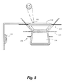
- FIG. 5 shows an LED light fixture configured for installation in a drop ceiling according to at least one embodiment.
- the one or more embodiments disclosed herein provide for an LED light fixture of any wattage to be adjustable, thus allowing purchasers to purchase one light fixture that is capable of adjustment to a wide range of settings for wattage and lumen output.
- the one or more embodiments disclosed herein can be adapted to a variety of state of the art LED light fixtures to achieve the result of wattage and lumen output control.
- the circuit 10 includes a dimming controller or control module 12 .
- the dimming controller 12 may be, for example, a 0-10V dimmer.
- the dimming controller 12 may be a PWM.
- the PWM controls the pulse of power from the switch box 15 to downstream, where the switch box 15 includes the dimming controller 12 .
- the switch box 15 also may include an AC to DC transformer. Additionally, the switch box 15 may include one or more additional features such as additional switches going to other outlets and the like.
- the dimming controller 12 may be selectively adjustable by turning off of a knob, selecting a desired dial level, or by smart adjustments that may be effectuated by selecting a desired dimming level on a touch-responsive control panel.
- the circuit 10 may further include an adjustable resistor 14 .
- the adjustable resistor 14 may be connected downstream of and in series connection with the dimming controller 12 and switch box 15 .
- the adjustable resistor 14 may be a slide resistor.
- the adjustable resistor 14 may be a linear potentiometer.
- the circuit 10 may further include a driver 16 connected downstream and in series with the adjustable resistor 14 .
- the driver 16 is an internal mechanism that regulates power to a light source, and is advantageously used with LED light sources to vary the power supplied to the LED as the LED properties change with temperature changes.
- the circuit 10 may include a light connected downstream and in series with the driver 16 .
- a light may be any appropriately configured light, and each of an LED 20 , fluorescent tube 22 , and incandescent light 24 are illustrated as one embodiment thereof.
- adjustable resistor 14 may be enclosed within the light assembly when installed and therefore not accessible to outside without removal of the light. This allows the installer to adjust the wattage and lumen output at the time of installation but does not allow subsequent altering of the wattage and lumen output without some barrier to doing so, namely removal of the light assembly to access the linear resistor.
- adjustable resistor 14 may be selectively adjustable by a smart control system or have authentication/authorization permissions associated with an adjustment.
- an LED roadway I street lamp can be adjusted by the purchaser, installer, or owner to an optimal wattage and lumen output for the particular installation environment of the LED light fixture.
- the purchaser can purchase a single LED roadway lamp of the present invention for all installation points and “tune” the wattage and lumen output of each light fixture to the optimal wattage and lumen output for each installation point.
- the one or more embodiments disclosed herein allow for near infinite wattage and lumen control adjustment up to the maximum rated output for the LED light array of the light fixture.
- the one or more embodiments disclosed herein provide for a hybrid lighting control system to prevent the dimmer 12 from overriding the wattage limiter, where the adjustable resistor 14 is the wattage limiter on the entire circuit.
- This system combines the use of a primary adjustable resistor 14 that is connected to the driver 16 of the light fixture.
- the primary adjustable resistor 14 such as a slide resistor or linear potentiometer, is used to preset or limit the maximum wattage of the fixture.
- a secondary resistance type 12 , wall, PC, remote or other dimmer e.g. 0-1 OV or PWM
- the secondary dimmer 12 can also be applied to the fixture to allow the end user to adjust the light level up or down.
- the primary controller (the adjustable resistor 14 ) will prevent the secondary dimming controller 12 from overriding the maximum wattage preset at the light fixture. This allows dimming for the customer, without surpassing the maximum wattage chosen. This allows an ESC to acquire their Return of Investment within their estimated timeframe and, even sooner if the dimmer is used often.
- This hybrid lighting control system allows ESCo's the ability to purchase fixtures in advance, which saves them time, money and labor as, no matter the wattage desired by the ESCo or, the intensity of light demanded by the client, this new system can be adjusted precisely to meet both parties' expectations.
- the one or more methods 100 may include adjusting an adjustable resistor to a desired wattage output 102 .
- the adjustable resistor is in series connection with a driver of the light.
- the one or more methods 100 may include adjusting a dimming control to a desired luminosity output 104 .
- the dimming controller is in series connection with the adjustable resistor.
- the one or more methods 200 may include determining a maximum wattage output for a given light fixture 202 . This may be requested by the customer or decided on by the installer, or may be mandated by a government or contract.
- the one or more methods 200 may include adjusting the adjustable resistor to the maximum wattage output for a given light fixture 204 .
- the one or more methods 206 may further include installing the light fixture after adjusting the adjustable resistor to the maximum wattage output 206 .
- FIG. 4 shows an exemplary outdoor LED light fixture 400 configured for illuminating a roadway, including a light sensor 402 for automatic control of the LED light fixture.
- the trim pot adjuster 404 is located on the exterior of the light fixture housing 406 .
- Alternative embodiments may optionally have the trimpot adjuster inside the housing 406 to prevent unauthorized adjustments (tampering) of the light fixture.
- This embodiment and others allow a LED light fixture of any wattage to be adjustable, thus allowing purchasers to purchase one light fixture that is capable of adjustment to a wide range of settings for wattage and lumen output.
- the fixture can be adapted to a variety of state of the art LED light fixtures to achieve the result of wattage and lumen output control.
- the exemplary outdoor environment embodiment is shown in FIG.
- An LED roadway I street lamp embodiment shown in FIG. 4 includes the housing 406 , at least one LED light array 410 , the light sensor 402 (photo-cell or other sensor) to automatically power the light fixture on/off, a power source, lens, a driver to control the LED light array, a potentiometer (“trimpot”), and the trimpot adjuster 404 .
- the fixture includes a trim pot adjuster on the outside of the light fixture housing, as depicted in FIG. 4 .
- the present invention includes a trimpot adjuster that is not accessible on the outside of the light fixture housing. Thus, unauthorized adjustments (tampering) of the LED light fixture wattage and lumen output is inhibited.
- a trim pot which provides an electrical signal that leads back into the driver.
- this electrical signal then flows through a pulse-width modulator, which controls the pulse of power coming out of the driver to the LED array.
- the wattage output is set at a certain level, by adjusting the trimpot adjuster, which becomes the maximum output for the LED array, until such time as the trimpot is adjusted to increase or decrease the wattage flow.
- the increased or decreased wattage flow to the LED array thus adjusts, either up or down, the lumen output of the LED array, and thus the LED light fixture.
- the trimpot adjuster can be in any useable form, including physical and/or electromagnetic adjuster devices.
- a trimpot adjuster that is a slide switch that can be slidably adjusted to control the trimpot signals to the driver.
- the trimpot adjuster is a knob that can be rotatably adjusted to control the trimpot signals to the driver.
- the trimpot adjuster is a receiver for receiving electromagnetic control signals, which could be in the form of RF, WiFi, or other useful electromagnetic form, to control the trimpot signals to the driver.
- Such trimpot adjuster devices will allow remote control for one or more light fixtures at a time.
- Electromagnetic adjuster devices may optionally be configured to require a passcode or other tamper-resistant means.
- both a physical adjuster device (knob, slide, or other useful form) and an electromagnetic adjuster device (RF, WiFi, or other useful electromagnetic form) are used.
- the trimpot adjuster By using the trimpot adjuster, the purchaser, installer, or owner is no longer confined to the factory pre-set wattage and lumen output of industry-standard outdoor LED light fixtures.
- the LED roadway I street lamp depicted in FIG. 4 can be adjusted by the purchaser, installer, or owner to an optimal wattage and lumen output for the particular installation environment of the LED light fixture.
- the purchaser can purchase a single LED roadway lamp according to embodiments herein for all installation points and “tune” the wattage and lumen output of each light fixture to the optimal wattage and lumen output for each installation point. This allows for near infinite wattage and lumen control adjustment up to the maximum rated output for the LED light array of the light fixture. The resulting lighted environment will be both cost effective for the purchaser and safer for motorists.
- exemplary outdoor environment embodiments of the present invention include configurations for illuminating a variety of outdoor environments, including public parks, walkways and trails, parking lots, parking garages, commercial buildings, outdoor manufacturing facilities, outdoor signage, and aesthetic applications such as scenic environments or exteriors of residential and commercial/office structures.
- an LED light fixture of one or more embodiments herein can take on any required shape or form. Accordingly, some embodiments have only one LED array controlled by a single LED driver equipped with a trimpot adjuster. This may be an advantageous for a simple outdoor application environment, such as some roadway lamps, parking garage lamps, and parking lot lamps. Other embodiments, however, may have more than one LED array.
- the LED arrays in these embodiments may be controlled by a single LED driver or one LED driver per LED array, where one or more of the LED drivers are equipped with a trimpot adjuster.
- a more complicated outdoor application environment may require the flexibility of more than one adjustable LED array, such as complex roadway environments or building exteriors where different lumen outputs, light shape or coverage, and/or light focal direction may be desired.
- still further embodiments are equipped with modular, replaceable LED arrays and/or LED drivers to allow for further adjustment capabilities and/or repair and service options that are currently not available in the marketplace for LED light fixtures.
- FIG. 5 shows an exemplary indoor LED light fixture 500 configured for installation in a drop ceiling.
- Two alternative positions of the trimpot adjuster 502 are shown.
- a trimpot adjuster could optionally be located on top of the LED light fixture hidden from view above the drop ceiling panels 504 to prevent unauthorized adjustments (tampering) of the light fixture 500 .
- a trimpot adjuster could optionally be located in the interior of the LED light fixture accessible only be removing the lens cover 506 to prevent unauthorized adjustments (tampering) of the light fixture.
- a trimpot adjuster could optionally be located in a position on the exterior of the LED light fixture (not depicted) for unhindered access, for example, by a home owner. Also depicted is a wall mounted dimmer 508 that works independently of the trimpot and trimpot adjuster.
- the indoor LED light fixture 500 embodiment for installation in a drop ceiling installation point shown in FIG. 5 includes a housing 510 , at least one LED light array, a power source, drop down lens cover 506 , a driver to control the LED light array, and a trimpot adjuster.
- a trimpot adjuster is concealed from the casual observer above the drop ceiling panels on the top of the light fixture housing, as depicted in FIG. 5 .
- a trimpot adjuster is visible, but not accessible on the outside of the light fixture housing by placement in the interior of the light fixture behind the lens cover, as also depicted in FIG. 5 .
- a trimpot adjuster is visible and purposefully accessible to the purchaser, installer, or owner (e.g., a home owner or shop owner) for ready access to adjusting the LED light fixture wattage and lumen output.
- FIG. 5 Also shown in FIG. 5 is a wall mounted dimmer switch 512 as a secondary way to control some embodiments of the LED light fixture.
- These devices are distinct from a “light dimmer” because a dimmer employs either a resistor(s) or it “chops up” (turns the light on and off in rapid succession). These devices enable the purchaser, installer, or owner to “set” or “tune” any desired wattage output (up to the rated wattage output for that light fixture), which in turn affects the maximum lumen output of the light. Therefore, a dimmer switch could be used in conjunction with these devices to further control the LED light fixture.
- the trimpot adjuster can be in any useable form, including physical and/or electromagnetic adjuster devices.
- a trimpot adjuster that is a slide switch that can be slidably adjusted to control the trimpot signals to the driver.
- the trimpot adjuster is a knob that can be rotatably adjusted to control the trimpot signals to the driver.
- the trimpot adjuster is a receiver for receiving electromagnetic control signals, which could be in the form of RF, WiFi, or other useful electromagnetic form, to control the trimpot signals to the driver.
- Such trimpot adjuster devices will allow remote control for one or more light fixtures at a time.
- Electromagnetic adjuster devices may optionally be configured to require a passcode or other tamper-resistant means.
- both a physical adjuster device (knob, slide, or other useful form) and an electromagnetic adjuster device (RF, WiFi, or other useful electromagnetic form) are used.
- exemplary indoor environment embodiments include configurations for illuminating a variety of indoor environments, including indoor public spaces (libraries, offices, lobbies, terminals, etc.), residential spaces, commercial office space, commercial retail space, elevators and stairwells, indoor manufacturing and laboratory environments, indoor agricultural or horticultural spaces, museums, and any other indoor spaces where lighting control is desirable.
- indoor public spaces libraries, offices, lobbies, terminals, etc.
- residential spaces commercial office space
- commercial retail space commercial retail space
- elevators and stairwells indoor manufacturing and laboratory environments
- indoor agricultural or horticultural spaces museums, and any other indoor spaces where lighting control is desirable.
- the shape or form of the LED light fixture for indoor environments may change given the indoor application, anticipated installation environment(s), and other criteria. Accordingly, some embodiments have only one LED array controlled by a single LED driver equipped with a trimpot adjuster. This may be an advantageous for a simple indoor application environment, such as common residential or commercial retail indoor light fixtures.
- the exemplary indoor environment LED light fixture according to at least one embodiment is in the form of a drop ceiling lighting fixture, a common lighting fixture type in commercial office and retail space, as well as residential applications.
- embodiments can be adapted to “light bulb” forms for use in standard light bulb applications, without limit, such as the Edison screw light bulb, “tube lights”, bi-pin, bayonet socket, fixed flood lamps, or other forms.
- a residential “light bulb” embodiment for use in a standard Edison screw base lamp may be so configured to comprise a slidably adjustable trimpot adjuster and/or a WiFi trimpot adjuster allowing a home owner to adjust the wattage and lumen output of the light fixture physically or remotely via an Internet connection.
- Other embodiments may include more than one LED array, such as horticultural fixtures, some “tube” light fixtures, or large light fixtures.
- the LED arrays in these embodiments are controlled by a single LED driver or one LED driver per LED array, where one or more of the LED drivers are equipped with a trimpot adjuster.
- a more complicated indoor application environment may require the flexibility of more than one adjustable LED array, such as indoor manufacturing spaces where different lighting conditions are required for adjacent spaces.
- Still further embodiments are equipped with replaceable LED arrays and/or LED drivers to allow for further adjustment capabilities and/or repair and service options that are currently not available in the marketplace for LED light fixtures. These embodiments would allow the consumer or end-user to replace a component of the module (such as the LED board or LED driver) and change the settings via a trimpot or similar device.
- a potentiometer (“trimpot”) or other device is capable of making adjustments to output control signals of the LED driver, which allows the purchaser, installer, or owner of the LED light fixture to adjust the effective wattage of the LED array(s). This in turn adjusts/controls the maximum lumen output of the LED light fixture, and enables adjustability for pole height, terrain, or other environmental variability at the installation location, in the context of a LED roadway light fixture, for example.
- the trimpot adjuster could be less dynamic than described above in the form of a knob or slidable adjuster and only provide switches or buttons that adjust the LED light fixture wattage and lumen output to a finite set of adjustments (two, three, four, etc.). Operation of such a trim pot adjuster would allow for an installer to selectively choose a predetermined wattage output based upon discrete markings that indicate the finite set of adjustments.
- the installer could selectively adjust the trim pot adjuster to indicate that a particular number such as “2” in order to limit the maximum output of the light fixture to a wattage and lumens associated with that number.
Landscapes
- Engineering & Computer Science (AREA)
- General Engineering & Computer Science (AREA)
- Circuit Arrangement For Electric Light Sources In General (AREA)
- Non-Portable Lighting Devices Or Systems Thereof (AREA)
Abstract
Description
Claims (20)
Priority Applications (1)
| Application Number | Priority Date | Filing Date | Title |
|---|---|---|---|
| US15/213,779 US9801245B2 (en) | 2013-07-26 | 2016-07-19 | Light fixture |
Applications Claiming Priority (4)
| Application Number | Priority Date | Filing Date | Title |
|---|---|---|---|
| US201361859031P | 2013-07-26 | 2013-07-26 | |
| US201461951480P | 2014-03-11 | 2014-03-11 | |
| US14/444,997 US20150028776A1 (en) | 2013-07-26 | 2014-07-28 | Lighting control systems and methods |
| US15/213,779 US9801245B2 (en) | 2013-07-26 | 2016-07-19 | Light fixture |
Related Parent Applications (1)
| Application Number | Title | Priority Date | Filing Date |
|---|---|---|---|
| US14/444,997 Continuation US20150028776A1 (en) | 2013-07-26 | 2014-07-28 | Lighting control systems and methods |
Publications (2)
| Publication Number | Publication Date |
|---|---|
| US20170013691A1 US20170013691A1 (en) | 2017-01-12 |
| US9801245B2 true US9801245B2 (en) | 2017-10-24 |
Family
ID=52389917
Family Applications (2)
| Application Number | Title | Priority Date | Filing Date |
|---|---|---|---|
| US14/444,997 Abandoned US20150028776A1 (en) | 2013-07-26 | 2014-07-28 | Lighting control systems and methods |
| US15/213,779 Active US9801245B2 (en) | 2013-07-26 | 2016-07-19 | Light fixture |
Family Applications Before (1)
| Application Number | Title | Priority Date | Filing Date |
|---|---|---|---|
| US14/444,997 Abandoned US20150028776A1 (en) | 2013-07-26 | 2014-07-28 | Lighting control systems and methods |
Country Status (1)
| Country | Link |
|---|---|
| US (2) | US20150028776A1 (en) |
Cited By (2)
| Publication number | Priority date | Publication date | Assignee | Title |
|---|---|---|---|---|
| US20110318101A1 (en) * | 2009-02-18 | 2011-12-29 | Keum Kyu Kim | Construction and installation of a world standard rainbow highway made of rainbow colors and method thereof |
| US12435860B2 (en) | 2016-02-19 | 2025-10-07 | Signify Holding B.V. | Configurable lighting system |
Families Citing this family (20)
| Publication number | Priority date | Publication date | Assignee | Title |
|---|---|---|---|---|
| US20150028776A1 (en) | 2013-07-26 | 2015-01-29 | Enigma Universal Technologies, Llc | Lighting control systems and methods |
| SG2014003602A (en) * | 2014-01-16 | 2015-08-28 | Opulent Electronics Internat Pte Ltd | Dimmer system |
| US9386648B2 (en) * | 2014-12-05 | 2016-07-05 | Abl Ip Holding, Llc | Systems, apparatus, and methods for converting a bi-level lighting system to a dimmable lighting system |
| JP6489523B2 (en) * | 2015-03-12 | 2019-03-27 | パナソニックIpマネジメント株式会社 | Solid state light emitting device module and lighting set |
| US9506640B1 (en) * | 2015-10-02 | 2016-11-29 | Palm Coast Imports, LLC | Conductive chain for touch dimming overhead lights |
| US11686459B2 (en) | 2015-12-15 | 2023-06-27 | Wangs Alliance Corporation | LED lighting methods and apparatus |
| US10323832B2 (en) | 2015-12-15 | 2019-06-18 | Wangs Alliance Corporation | LED lighting methods and apparatus |
| TWI596983B (en) | 2016-06-01 | 2017-08-21 | 酷異有限公司 | Modular light control device and dimming control system |
| US10129945B2 (en) | 2017-01-29 | 2018-11-13 | Gooee Limited | Modular light control system |
| US10438980B2 (en) * | 2017-05-31 | 2019-10-08 | Taiwan Semiconductor Manufacturing Co., Ltd. | Image sensor with a high absorption layer |
| US11812525B2 (en) | 2017-06-27 | 2023-11-07 | Wangs Alliance Corporation | Methods and apparatus for controlling the current supplied to light emitting diodes |
| US12281783B2 (en) | 2019-12-31 | 2025-04-22 | Lumien Enterprise, Inc. | Electronic module group |
| US11598517B2 (en) | 2019-12-31 | 2023-03-07 | Lumien Enterprise, Inc. | Electronic module group |
| CN110985903B (en) | 2019-12-31 | 2020-08-14 | 江苏舒适照明有限公司 | Lamp module |
| CN111503556B (en) | 2020-04-23 | 2020-11-27 | 江苏舒适照明有限公司 | a spotlight structure |
| US11812532B2 (en) | 2021-05-27 | 2023-11-07 | Wangs Alliance Corporation | Multiplexed segmented lighting lamina |
| US12230950B2 (en) | 2021-07-29 | 2025-02-18 | Lumien Enterprise, Inc. | Junction box |
| US11802682B1 (en) | 2022-08-29 | 2023-10-31 | Wangs Alliance Corporation | Modular articulating lighting |
| US12513799B2 (en) | 2023-07-25 | 2025-12-30 | Wangs Alliance Corporation | Off-fixture lighting control circuit |
| US12292169B1 (en) | 2024-07-10 | 2025-05-06 | Wangs Alliance Corporation | Shadowless connector |
Citations (9)
| Publication number | Priority date | Publication date | Assignee | Title |
|---|---|---|---|---|
| US4933603A (en) | 1988-11-01 | 1990-06-12 | Audi Ag | Circuit arrangement for indicator lights in motor vehicles |
| US5744913A (en) * | 1994-03-25 | 1998-04-28 | Pacific Scientific Company | Fluorescent lamp apparatus with integral dimming control |
| US20080224633A1 (en) * | 2007-03-12 | 2008-09-18 | Cirrus Logic, Inc. | Lighting System with Lighting Dimmer Output Mapping |
| US20090278479A1 (en) | 2008-05-06 | 2009-11-12 | Platner Brian P | Networked, wireless lighting control system with distributed intelligence |
| US20100066260A1 (en) | 2008-09-05 | 2010-03-18 | Lutron Electronics Co., Inc. | Hybrid light source |
| US20110148318A1 (en) * | 2008-11-28 | 2011-06-23 | Lightech Electronic Industries Ltd. | Phase controlled dimming led driver system and method thereof |
| US20120223658A1 (en) * | 2011-03-03 | 2012-09-06 | Osram Ag | Lamp and luminaire with at least one light emitting diode |
| US20130163243A1 (en) * | 2011-12-06 | 2013-06-27 | Express Imaging Systems, Llc | Adjustable output solid-state lighting device |
| US20150028776A1 (en) | 2013-07-26 | 2015-01-29 | Enigma Universal Technologies, Llc | Lighting control systems and methods |
-
2014
- 2014-07-28 US US14/444,997 patent/US20150028776A1/en not_active Abandoned
-
2016
- 2016-07-19 US US15/213,779 patent/US9801245B2/en active Active
Patent Citations (9)
| Publication number | Priority date | Publication date | Assignee | Title |
|---|---|---|---|---|
| US4933603A (en) | 1988-11-01 | 1990-06-12 | Audi Ag | Circuit arrangement for indicator lights in motor vehicles |
| US5744913A (en) * | 1994-03-25 | 1998-04-28 | Pacific Scientific Company | Fluorescent lamp apparatus with integral dimming control |
| US20080224633A1 (en) * | 2007-03-12 | 2008-09-18 | Cirrus Logic, Inc. | Lighting System with Lighting Dimmer Output Mapping |
| US20090278479A1 (en) | 2008-05-06 | 2009-11-12 | Platner Brian P | Networked, wireless lighting control system with distributed intelligence |
| US20100066260A1 (en) | 2008-09-05 | 2010-03-18 | Lutron Electronics Co., Inc. | Hybrid light source |
| US20110148318A1 (en) * | 2008-11-28 | 2011-06-23 | Lightech Electronic Industries Ltd. | Phase controlled dimming led driver system and method thereof |
| US20120223658A1 (en) * | 2011-03-03 | 2012-09-06 | Osram Ag | Lamp and luminaire with at least one light emitting diode |
| US20130163243A1 (en) * | 2011-12-06 | 2013-06-27 | Express Imaging Systems, Llc | Adjustable output solid-state lighting device |
| US20150028776A1 (en) | 2013-07-26 | 2015-01-29 | Enigma Universal Technologies, Llc | Lighting control systems and methods |
Cited By (2)
| Publication number | Priority date | Publication date | Assignee | Title |
|---|---|---|---|---|
| US20110318101A1 (en) * | 2009-02-18 | 2011-12-29 | Keum Kyu Kim | Construction and installation of a world standard rainbow highway made of rainbow colors and method thereof |
| US12435860B2 (en) | 2016-02-19 | 2025-10-07 | Signify Holding B.V. | Configurable lighting system |
Also Published As
| Publication number | Publication date |
|---|---|
| US20150028776A1 (en) | 2015-01-29 |
| US20170013691A1 (en) | 2017-01-12 |
Similar Documents
| Publication | Publication Date | Title |
|---|---|---|
| US9801245B2 (en) | Light fixture | |
| KR102421727B1 (en) | Led driving apparatus | |
| JP6466929B2 (en) | Method and apparatus for controlling lighting based on a combination of inputs | |
| US8022641B2 (en) | Recessed LED down light | |
| CN107432069B (en) | System and method for generating light representing natural light of an object | |
| US20180279429A1 (en) | Solid State Lighting Systems | |
| US9854640B2 (en) | Solid-state lighting control with dimmability and color temperature tunability using low voltage controller | |
| US20160234899A1 (en) | Luminaire with adjustable illumination pattern | |
| US20080224849A1 (en) | Multifunctional lighting system | |
| US20130250579A1 (en) | Led fixture with integrated driver circuitry | |
| EP2350526A2 (en) | Distributed illumination system | |
| AU2024211851A1 (en) | Extended knuckle, snout, and aiming device for retrofitting a lighting system with led lights | |
| US8858031B2 (en) | Light engine device with direct to linear system driver | |
| US12352393B2 (en) | Lighting apparatus | |
| US12163631B1 (en) | Solid state lighting driver and lamp replacement for avionics ballast and fluorescent lamp | |
| KR101152789B1 (en) | The led lamp illumination control apparatus using zigbee | |
| US11116066B2 (en) | LED light system with remote controlled LED lamps having individually controlled zones | |
| US20180227999A1 (en) | Optical systems for variable correlated color temperature | |
| KR101045595B1 (en) | Lighting Control Device for Halogen Lamp Using Zigbee | |
| Benya et al. | Lighting Retrofit and Relighting: A Guide to Energy Efficient Lighting | |
| Shackelford et al. | Retrofit demonstration of LED fixtures with integrated sensors and controls | |
| Eizadi | eizadi@ kth. se | |
| Kumar et al. | Light Right a practising engineer's manual on energy-efficient lighting: prospects and constraints | |
| US20170164442A1 (en) | Mercury-Vapor Like Lamp | |
| Eichelberger | LEDs come to the forefront of general lighting applications |
Legal Events
| Date | Code | Title | Description |
|---|---|---|---|
| STCF | Information on status: patent grant |
Free format text: PATENTED CASE |
|
| MAFP | Maintenance fee payment |
Free format text: PAYMENT OF MAINTENANCE FEE, 4TH YR, SMALL ENTITY (ORIGINAL EVENT CODE: M2551); ENTITY STATUS OF PATENT OWNER: SMALL ENTITY Year of fee payment: 4 |
|
| AS | Assignment |
Owner name: EPIC UNIVERSAL TECHNOLOGIES, LLC, NORTH CAROLINA Free format text: ASSIGNMENT OF ASSIGNORS INTEREST;ASSIGNOR:MCMILLAN, GEORGE ERIK;REEL/FRAME:058226/0229 Effective date: 20211123 Owner name: EPIC UNIVERSAL TECHNOLOGIES, LLC, NORTH CAROLINA Free format text: ASSIGNMENT OF ASSIGNOR'S INTEREST;ASSIGNOR:MCMILLAN, GEORGE ERIK;REEL/FRAME:058226/0229 Effective date: 20211123 |
|
| AS | Assignment |
Owner name: EPIC UNIVERSAL TECHNOLOGIES, LLC, NORTH CAROLINA Free format text: ASSIGNMENT OF ASSIGNORS INTEREST;ASSIGNOR:MCMILLAN, GEORGE ERIK;REEL/FRAME:058246/0251 Effective date: 20211123 Owner name: EPIC UNIVERSAL TECHNOLOGIES, LLC, NORTH CAROLINA Free format text: ASSIGNMENT OF ASSIGNOR'S INTEREST;ASSIGNOR:MCMILLAN, GEORGE ERIK;REEL/FRAME:058246/0251 Effective date: 20211123 |
|
| MAFP | Maintenance fee payment |
Free format text: PAYMENT OF MAINTENANCE FEE, 8TH YR, SMALL ENTITY (ORIGINAL EVENT CODE: M2552); ENTITY STATUS OF PATENT OWNER: SMALL ENTITY Year of fee payment: 8 |
|
| AS | Assignment |
Owner name: INVICTUS LIGHTING LLC, NORTH CAROLINA Free format text: ASSIGNMENT OF ASSIGNORS INTEREST;ASSIGNOR:EPIC UNIVERSAL TECHNOLOGIES, LLC;REEL/FRAME:071955/0454 Effective date: 20250715 |