US9800795B2 - Auto range control for active illumination depth camera - Google Patents
Auto range control for active illumination depth camera Download PDFInfo
- Publication number
- US9800795B2 US9800795B2 US14/977,140 US201514977140A US9800795B2 US 9800795 B2 US9800795 B2 US 9800795B2 US 201514977140 A US201514977140 A US 201514977140A US 9800795 B2 US9800795 B2 US 9800795B2
- Authority
- US
- United States
- Prior art keywords
- camera
- sequence
- projector
- intensity
- images captured
- Prior art date
- Legal status (The legal status is an assumption and is not a legal conclusion. Google has not performed a legal analysis and makes no representation as to the accuracy of the status listed.)
- Active
Links
Images


Classifications
-
- F—MECHANICAL ENGINEERING; LIGHTING; HEATING; WEAPONS; BLASTING
- F16—ENGINEERING ELEMENTS AND UNITS; GENERAL MEASURES FOR PRODUCING AND MAINTAINING EFFECTIVE FUNCTIONING OF MACHINES OR INSTALLATIONS; THERMAL INSULATION IN GENERAL
- F16K—VALVES; TAPS; COCKS; ACTUATING-FLOATS; DEVICES FOR VENTING OR AERATING
- F16K17/00—Safety valves; Equalising valves, e.g. pressure relief valves
- F16K17/02—Safety valves; Equalising valves, e.g. pressure relief valves opening on surplus pressure on one side; closing on insufficient pressure on one side
-
- H04N5/2355—
-
- F—MECHANICAL ENGINEERING; LIGHTING; HEATING; WEAPONS; BLASTING
- F15—FLUID-PRESSURE ACTUATORS; HYDRAULICS OR PNEUMATICS IN GENERAL
- F15B—SYSTEMS ACTING BY MEANS OF FLUIDS IN GENERAL; FLUID-PRESSURE ACTUATORS, e.g. SERVOMOTORS; DETAILS OF FLUID-PRESSURE SYSTEMS, NOT OTHERWISE PROVIDED FOR
- F15B15/00—Fluid-actuated devices for displacing a member from one position to another; Gearing associated therewith
- F15B15/02—Mechanical layout characterised by the means for converting the movement of the fluid-actuated element into movement of the finally-operated member
- F15B15/06—Mechanical layout characterised by the means for converting the movement of the fluid-actuated element into movement of the finally-operated member for mechanically converting rectilinear movement into non- rectilinear movement
- F15B15/063—Actuator having both linear and rotary output, i.e. dual action actuator
-
- F—MECHANICAL ENGINEERING; LIGHTING; HEATING; WEAPONS; BLASTING
- F16—ENGINEERING ELEMENTS AND UNITS; GENERAL MEASURES FOR PRODUCING AND MAINTAINING EFFECTIVE FUNCTIONING OF MACHINES OR INSTALLATIONS; THERMAL INSULATION IN GENERAL
- F16K—VALVES; TAPS; COCKS; ACTUATING-FLOATS; DEVICES FOR VENTING OR AERATING
- F16K1/00—Lift valves or globe valves, i.e. cut-off apparatus with closure members having at least a component of their opening and closing motion perpendicular to the closing faces
- F16K1/16—Lift valves or globe valves, i.e. cut-off apparatus with closure members having at least a component of their opening and closing motion perpendicular to the closing faces with pivoted closure-members
- F16K1/18—Lift valves or globe valves, i.e. cut-off apparatus with closure members having at least a component of their opening and closing motion perpendicular to the closing faces with pivoted closure-members with pivoted discs or flaps
- F16K1/22—Lift valves or globe valves, i.e. cut-off apparatus with closure members having at least a component of their opening and closing motion perpendicular to the closing faces with pivoted closure-members with pivoted discs or flaps with axis of rotation crossing the valve member, e.g. butterfly valves
-
- F—MECHANICAL ENGINEERING; LIGHTING; HEATING; WEAPONS; BLASTING
- F16—ENGINEERING ELEMENTS AND UNITS; GENERAL MEASURES FOR PRODUCING AND MAINTAINING EFFECTIVE FUNCTIONING OF MACHINES OR INSTALLATIONS; THERMAL INSULATION IN GENERAL
- F16K—VALVES; TAPS; COCKS; ACTUATING-FLOATS; DEVICES FOR VENTING OR AERATING
- F16K1/00—Lift valves or globe valves, i.e. cut-off apparatus with closure members having at least a component of their opening and closing motion perpendicular to the closing faces
- F16K1/32—Details
- F16K1/34—Cutting-off parts, e.g. valve members, seats
-
- F—MECHANICAL ENGINEERING; LIGHTING; HEATING; WEAPONS; BLASTING
- F16—ENGINEERING ELEMENTS AND UNITS; GENERAL MEASURES FOR PRODUCING AND MAINTAINING EFFECTIVE FUNCTIONING OF MACHINES OR INSTALLATIONS; THERMAL INSULATION IN GENERAL
- F16K—VALVES; TAPS; COCKS; ACTUATING-FLOATS; DEVICES FOR VENTING OR AERATING
- F16K31/00—Actuating devices; Operating means; Releasing devices
- F16K31/12—Actuating devices; Operating means; Releasing devices actuated by fluid
- F16K31/36—Actuating devices; Operating means; Releasing devices actuated by fluid in which fluid from the circuit is constantly supplied to the fluid motor
- F16K31/363—Actuating devices; Operating means; Releasing devices actuated by fluid in which fluid from the circuit is constantly supplied to the fluid motor the fluid acting on a piston
-
- G—PHYSICS
- G01—MEASURING; TESTING
- G01B—MEASURING LENGTH, THICKNESS OR SIMILAR LINEAR DIMENSIONS; MEASURING ANGLES; MEASURING AREAS; MEASURING IRREGULARITIES OF SURFACES OR CONTOURS
- G01B11/00—Measuring arrangements characterised by the use of optical techniques
- G01B11/24—Measuring arrangements characterised by the use of optical techniques for measuring contours or curvatures
- G01B11/25—Measuring arrangements characterised by the use of optical techniques for measuring contours or curvatures by projecting a pattern, e.g. one or more lines, moiré fringes on the object
-
- H—ELECTRICITY
- H04—ELECTRIC COMMUNICATION TECHNIQUE
- H04N—PICTORIAL COMMUNICATION, e.g. TELEVISION
- H04N23/00—Cameras or camera modules comprising electronic image sensors; Control thereof
- H04N23/20—Cameras or camera modules comprising electronic image sensors; Control thereof for generating image signals from infrared radiation only
-
- H—ELECTRICITY
- H04—ELECTRIC COMMUNICATION TECHNIQUE
- H04N—PICTORIAL COMMUNICATION, e.g. TELEVISION
- H04N23/00—Cameras or camera modules comprising electronic image sensors; Control thereof
- H04N23/56—Cameras or camera modules comprising electronic image sensors; Control thereof provided with illuminating means
-
- H—ELECTRICITY
- H04—ELECTRIC COMMUNICATION TECHNIQUE
- H04N—PICTORIAL COMMUNICATION, e.g. TELEVISION
- H04N23/00—Cameras or camera modules comprising electronic image sensors; Control thereof
- H04N23/70—Circuitry for compensating brightness variation in the scene
- H04N23/71—Circuitry for evaluating the brightness variation
-
- H—ELECTRICITY
- H04—ELECTRIC COMMUNICATION TECHNIQUE
- H04N—PICTORIAL COMMUNICATION, e.g. TELEVISION
- H04N23/00—Cameras or camera modules comprising electronic image sensors; Control thereof
- H04N23/70—Circuitry for compensating brightness variation in the scene
- H04N23/73—Circuitry for compensating brightness variation in the scene by influencing the exposure time
-
- H—ELECTRICITY
- H04—ELECTRIC COMMUNICATION TECHNIQUE
- H04N—PICTORIAL COMMUNICATION, e.g. TELEVISION
- H04N23/00—Cameras or camera modules comprising electronic image sensors; Control thereof
- H04N23/70—Circuitry for compensating brightness variation in the scene
- H04N23/74—Circuitry for compensating brightness variation in the scene by influencing the scene brightness using illuminating means
-
- H—ELECTRICITY
- H04—ELECTRIC COMMUNICATION TECHNIQUE
- H04N—PICTORIAL COMMUNICATION, e.g. TELEVISION
- H04N23/00—Cameras or camera modules comprising electronic image sensors; Control thereof
- H04N23/70—Circuitry for compensating brightness variation in the scene
- H04N23/741—Circuitry for compensating brightness variation in the scene by increasing the dynamic range of the image compared to the dynamic range of the electronic image sensors
-
- H04N5/2256—
-
- H04N5/2353—
-
- H04N5/2354—
Definitions
- Embodiments of the present invention relate to the field of camera systems that perform three-dimensional (3-D) measurements by use of triangulation capturing one or more images with the assistance of one or more patterns projected by a projector; more particularly, embodiments of the present invention relate to performing auto range control of such camera systems.
- Stereo depth cameras are well-known and are often used to measure a distance from an object.
- One such measurement device includes a projector and a camera and is often included in a coded-light three-dimensional (3D) camera system.
- the projector projects a known pattern (e.g., a sequence of binary code patterns (e.g., vertical stripes)) on an object (e.g., a scene), and an image of the object upon which the image is projected is captured by the camera. From the captured images, depth information may be determined.
- a known pattern e.g., a sequence of binary code patterns (e.g., vertical stripes)
- an object e.g., a scene
- depth information may be determined.
- One technique for determining depth in such devices is through the use of triangulation from the known relative positions of the camera and a projector. Thus, images of objects are captured and measurements are taken to determine depth information.
- FIG. 1 illustrates one embodiment of an active coded light triangulation system.
- FIG. 2 is a flow diagram of one embodiment of a process for controlling the depth dynamic range.
- FIG. 3 is a flow diagram of one embodiment of the process for controlling the depth dynamic range by controlling the light power and the exposure time.
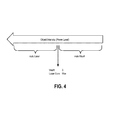
- FIG. 4 illustrates one embodiment of the auto gain and auto exposure domain of operation.
- FIG. 5 illustrates one embodiment of an example system.
- FIG. 6 illustrates an embodiment of a computing environment capable of supporting the operations described herein.
- Coupled may mean one or more of the following. “Coupled” may mean that two or more elements are in direct physical, electrical, or optical contact. However, “coupled” may also mean that two or more elements indirectly contact each other, but yet still cooperate or interact with each other, and may mean that one or more other elements are coupled or connected between the elements that are said to be coupled with each other.
- directly coupled may mean that two or more elements are in direct contact.
- FIG. 1 illustrates one embodiment of an active coded light triangulation system.
- the system includes coded light range cameras operating by projecting a sequence of one-dimensional binary (“black” and “white”) patterns onto a scene, such that the produced binary code encodes the angle of the projection plane. Depth is then reconstructed by triangulation consisting of computing the intersection of an imaginary ray emanating from the camera with the plane emanating from the projector.
- capture device 100 may include a 3D scanner, a 3D camera or any other device configured for a 3D object acquisition.
- capture device 100 includes an image capturing device 102 (e.g., a digital camera) and a projector unit 104 , such as a laser projector or laser scanner, having a number of components.
- image capturing device 102 e.g., a digital camera
- projector unit 104 such as a laser projector or laser scanner, having a number of components.
- digital camera 102 may comprise an infrared (IR) camera
- the projector unit 104 may comprise an IR projector.
- Projector unit 104 is configured to project a light pattern as described above and may comprise a one-dimensional code projector.
- the light patterns comprise one-dimensional coded light patterns, e.g., the patterns that may be described by one-dimensional or linear codes.
- the light patterns formed by the laser planes on a surface of the object may be received by image capturing device 102 and sensed (e.g., read) by a sensor of image capturing device 102 . Based on the readings of the multiple scans of the light patterns accumulated during a sensing cycle of the sensor, capture device 100 may be configured to reconstruct the shape of the object.
- capture device 100 may further include another image capturing device, such as digital camera 103 .
- digital camera 103 may have a resolution that is different than that of digital camera 103 .
- digital camera 102 may be a multi-chromatic camera, such as red, green, and blue (RGB) camera configured to capture texture images of an object.
- RGB red, green, and blue
- Capture device 100 may further include a processor 106 that may be in operative communication with the image camera component 101 over a bus or interconnect 107 .
- Processor 106 may include a standardized processor, a specialized processor, a microprocessor, or the like that may execute instructions that may include instructions for generating depth information, generating a depth image, determining whether a suitable target may be included in the depth image, or performing other operations described herein.
- Processor 106 may be configured to reconstruct the object based on the images captured by digital camera 102 , for example, using geometry techniques or other techniques used for 3D image reconstruction. Processor 106 may be further configured to dynamically calibrate capture device 100 to correct distortions in the reconstructed image of the object that may be caused, for example, by various external factors (e.g., temperature).
- various external factors e.g., temperature
- Capture device 100 may further include a memory 105 that may store the instructions that may be executed by processor 106 , images or frames of images captured by the cameras, user profiles or any other suitable information, images, or the like.
- memory 105 may include random access memory (RAM), read only memory (ROM), cache, Flash memory, a hard disk, or any other suitable storage component.
- RAM random access memory
- ROM read only memory
- cache Flash memory
- hard disk or any other suitable storage component.
- memory component 105 may be a separate component in communication with the cameras 101 and processor 106 .
- memory 105 may be integrated into processor 106 and/or the image capture cameras 101 .
- some or all of the components 102 - 106 are located in a single housing.
- Processor 105 may be coupled with one or more interfaces (not shown) configured to facilitate information exchange among the above-mentioned components.
- Communications interface(s) may provide an interface for device 100 to communicate over one or more wired or wireless network(s) and/or with any other suitable device.
- capture device 100 may be included to or associated with, but is not limited to, a server, a workstation, a desktop computing device, or a mobile computing device (e.g., a laptop computing device, a handheld computing device, a handset, a tablet, a smartphone, a netbook, ultrabook, etc.).
- capture device 100 is integrated into a computer system (e.g., laptop, personal computer (PC), etc.).
- a computer system e.g., laptop, personal computer (PC), etc.
- capture device 100 can be alternatively configured as a standalone device that is couplable to such a computer system using conventional technologies including both wired and wireless connections.
- capture device 100 may have more or less components, and/or different architectures.
- capture device 100 may include one or more of a camera, a keyboard, display such as a liquid crystal display (LCD) screen (including touch screen displays), a touch screen controller, non-volatile memory port, antenna or multiple antennas, graphics chip, ASIC, speaker(s), a battery, an audio codec, a video codec, a power amplifier, a global positioning system (GPS) device, a compass, an accelerometer, a gyroscope, and the like.
- display such as a liquid crystal display (LCD) screen (including touch screen displays), a touch screen controller, non-volatile memory port, antenna or multiple antennas, graphics chip, ASIC, speaker(s), a battery, an audio codec, a video codec, a power amplifier, a global positioning system (GPS) device, a compass, an accelerometer, a gyroscope, and the like.
- GPS global positioning system
- Capture device 100 may be used for a variety of purposes, including, but not limited to, being part of a target recognition, analysis, and tracking system to recognize human and non-human targets in a capture area of the physical space without the use of special sensing devices attached to the subjects, uniquely identify them, and track them in three-dimensional space.
- Capture device 100 may be configured to capture video with depth information including a depth image that may include depth values via any suitable technique including, for example, triangulation, time-of-flight, structured light, stereo image, or the like.
- Capture device 100 may be configured to operate as a depth camera that may capture a depth image of a scene.
- the depth image may include a two-dimensional (2D) pixel area of the captured scene where each pixel in the 2D pixel area may represent a depth value such as a distance in, for example, centimeters, millimeters, or the like of an object in the captured scene from the camera.
- capture device 100 includes an IR light projector 404 , an IR camera 102 , and a visible light RGB camera 103 that are configured in an array.
- capture device 100 may use structured light to capture depth information.
- patterned light i.e., light displayed as a known pattern such as a grid pattern or a stripe pattern
- IR light projector 104 may be projected onto the capture area via, for example, IR light projector 104 .
- the pattern may become deformed in response.
- Such a deformation of the pattern may be captured by, for example, he IR camera 102 and/or the RGB camera 103 and may then be analyzed to determine a physical distance from capture device 100 to a particular location on the targets or objects.
- Capture device 100 may utilize two or more physically separated cameras that may view a capture area from different angles, to obtain visual stereo data that may be resolved to generate depth information. Other types of depth image arrangements using single or multiple cameras can also be used to create a depth image.
- Capture device 100 may provide the depth information and images captured by, for example, IR camera 102 and/or the RGB camera 103 , including a skeletal model and/or facial tracking model that may be generated by capture device 100 , where the skeletal and/or facial tracking models, depth information, and captured images are used to, for example, create a virtual screen, adapt the user interface, and control an application.
- capture device 100 may comprise a projector unit 104 , a digital camera (e.g., IR camera) 102 , another digital camera (e.g., multi-chromatic camera) 103 , and a processor (controller) configured to operate capture device 100 according to the embodiments described herein.
- a digital camera e.g., IR camera
- another digital camera e.g., multi-chromatic camera
- processor controller
- capture device 100 may comprise a projector unit 104 , a digital camera (e.g., IR camera) 102 , another digital camera (e.g., multi-chromatic camera) 103 , and a processor (controller) configured to operate capture device 100 according to the embodiments described herein.
- a processor controller
- the system includes a controller to control the camera (e.g., IR camera) and the projector (e.g., IR projector) to perform range control.
- the controller is part of processor 106 , working in conjunction with software stored in memory 105 of the capture device of FIG. 1 .
- the controller controls both the power of the projected light from the projector and the exposure time of the camera to perform range control.
- the control of the power of the projected light from the projector and the exposure time of the camera is based on the scene analysis. In this case, the scene analysis involves determining the amount of light that is being reflected back from an object in the scene, as opposed to analyzing content in the scene.
- control results in an enlarged depth dynamic range in the near and far ends of the range.
- the dynamic range increases from 25 cm to 3 cm, while in the far end, the dynamic range goes from 70 cm to 1.8 m.
- the controller controls the exposure of the camera and/or the light (laser) power of the projector in order to avoid camera saturation at close range (e.g., less than 30 cm) of highly reflective objects at one near end of the dynamic range, while still being able to capture low reflective objects at a large distance at the other far end of the dynamic range.
- close range e.g., less than 30 cm
- the increased quality enables increased accuracy of depth profiles and allows the system to adapt itself to the operation environment to produce the best possible results.
- FIG. 2 is a flow diagram of one embodiment of a process for controlling the depth dynamic range.
- the process is performed by processing logic that may comprise hardware (circuitry, dedicated logic, etc.), software (such as is run on a general purpose computer system or a dedicated machine), firmware, or a combination of the three.
- the process begins by processing logic projecting a sequence of light patterns on an object (processing block 201 ).
- the processing logic is part of a projector.
- the processing logic is part of a controller sends control signals to the projector to cause the projector to project light onto the object.
- processing logic captures a sequence of images of the object illuminated with the projected light patterns using a camera (processing block 202 ).
- the processing logic is part of a controller sends control signals to the camera to cause the camera to capture the sequence of images of the illuminated object.
- processing logic controls the depth dynamic range of the camera by controlling the power of the sequence of light patterns being projected on the object by the projector and the exposure time of a camera (processing block 203 ).
- information is obtained from the captured sequence of images for use in controlling the depth dynamic range.
- the information comprises intensity information associated with a sequence of images captured by the camera.
- the intensity information comprises an average intensity of a difference between intensity of a sequence of images captured by the camera.
- the controller obtains its statistics from a sequence of captured images.
- the statistics are from the n ⁇ 1 sequence (e.g., the previous, or last, sequence of captured images) including: an image captured while the active light is on (e.g., the laser is on) referred to herein as I_1 and an image captured when the active light is off (e.g., the laser is off) referred to herein as I_0.
- the controller uses these two images.
- each of I_1 and I_0 is a matrix of the image, which each entry in the matrix being the value of the illumination of a pixel for the image. These values in corresponding locations in two matrices are subtracted from each other to obtain the icon image (Ic).
- the controller determines an average intensity value for the icon image.
- the average intensity value is determined by averaging all of the intensity values in the icon image (e.g., the intensity values in the icon image matrix). In another embodiment, the average intensity value is determined by averaging a subset of the intensity values of the icon image (e.g., the intensity values in the icon image matrix).
- the average intensity value of the icon image Ic, or power score, is denoted as Ps herein.
- the controller controls the depth dynamic range according to the following action rules:
- Threshold 1 is 1250 and Threshold 2 is 650. In one embodiment, these thresholds are learned statistically on several units and are dependent on the range of exposure values required and the effective Z field of view (FOV). For short range applications, in one embodiment, Threshold 1 is increased and Threshold 2 is decreased, and vice versa for far range applications.
- FOV effective Z field of view
- the laser gain increases and decreases are stepped at five percent of the range, while exposure increases and decreases are made at steps of 0.2 ms. Note that other step sizes may be used and the increase and decrease step sizes need not be the same. Note that in one embodiment, the increases and decreases are made based on recognizing that light follows an inverse-square law in that the intensity is inversely proportional to the square of the distance from the source of that physical quantity. Thus, in such cases, decreases and increases change quadratically, as opposed to following a linear path.
- FIG. 3 is a flow diagram of one embodiment of the process for controlling the depth dynamic range described above.
- the process is performed by processing logic that may comprise hardware (circuitry, dedicated logic, etc.), software (such as is run on a general purpose computer system or a dedicated machine), firmware, or a combination of the three.
- the controller compares the power score to a pair of thresholds, a first threshold and a second threshold, and controls depth dynamic range by:
- the controller the camera and projector using a number of different operations modes.
- These operational modes include an automatic (auto) laser gain mode, automatic (auto) exposure time mode, and auto laser gain with auto exposure time mode.
- the auto laser gain with auto exposure time mode controls the depth dynamic range of the camera by controlling the power of the sequence of light patterns being projected on the object by the projector and the exposure time of a camera using a number of operation modes. Each of these modes is discussed in more detail below.
- the controller When enabled, the controller decreases the laser gain if an object is close (or moves close) to the camera sensor to avoid saturation and increases the laser gain when the object moves away from the camera sensor.
- the controller has a default control setting to have the laser gain always be at the highest laser gain possible.
- the controller changes the exposure time automatically when the object gets far from the camera sensor to increase the dynamic range of the camera.
- the controller activates the auto laser gain when the object intensity rises.
- the controller increases the laser gain until it reaches the maximal value (e.g., preset maximum value).
- the controller activates the auto exposure and increases the exposure as required.
- the controller decreases the exposure until a minimal value (e.g., a preset minimum value) and activates the auto laser gain and so forth.
- FIG. 4 illustrates one embodiment of the auto gain and auto exposure domain of operation. Referring to FIG.
- the object intensity is shown with a point in the middle of the object intensity bar being the point where MsvR (Motion vs Range trade off, or exposure time) is equal to zero and the laser gain is at its maximum value.
- MsvR Motion vs Range trade off, or exposure time
- the controller uses auto laser gain control, while on the other side of the point (right), the controller use auto exposure control.
- the controller can only decrease laser while, while on the other side, the controller can only increase the exposure time.
- control algorithm uses an iconed version of the IR image (e.g., averaged and subsampled intensity IR image). In another embodiment, the control algorithm uses an IR image (created from the projector of the capture device).
- the algorithm outputs a decision to change either the laser power or the exposure.
- the output indication to change the power is as follows:
- the controller changes the laser power or the exposure control.
- parameters are configurable.
- the “power score” is calculated.
- the power score is calculated as follows. For each bin in a histogram calculated by the controller on a selected region of interest (ROI) in the icon image, the sum is calculated by multiplying the number of pixels in the bin by the bin index, and then that product is divided by the number of pixels multiplied by the maximum possible bin index (e.g., 255 ). In one embodiment, the following formula calculates the “power score” (average intensity [0,1]):
- the first three operations above determine the power score that is used to control the algorithm.
- the power scores are aggregated over consecutive image captures in time to determine if there is a trend.
- the window size is usually 1-3. In one embodiment, this is configurable.
- the scores are aggregated into an array.
- This condition determines if there is too much ambient light in the image: the dark image is to bright and the ration between the bright and dark images it too close to one according to one embodiment.
- this operation determines the amount of ambient light in the scene. If the amount of ambient light is too big, then the status is set to 1. If the amount of ambient light is too low, the status is set to 0. This is track so that in the case the ambient light is too big, then increasing the laser power and/or increasing the exposure is not performed to avoid increasing the amount of saturation. Note that in one embodiment, this is tracked over a number of consecutive image captures using a window (e.g., ten samples) to reduce the likelihood of noise influencing the process.
- a window e.g., ten samples
- the average of the values in the RelativeIRWindow is determined.
- the average (AvgStatus) is greater than 0.8, then there is too much ambient light, while if the average is less than 0.2, then there isn't too much ambient light.
- the controller controls the depth dynamic range using 8b-d below.
- the average score of the intensity values is greater than the sum of upper threshold (above which the power level is decreased) and the product of the slope of the threshold as a function of the power level and the current power level, then the current power level is reduced by 1, the window of intensity values is cleared and a variable tracking when the last change was made by the controller is reset (e.g., set to zero).
- the slope is meant to make it harder to cross reach distant power levels by increasing the threshold that the power score (Ps) should cross in order to get further from the target power level.
- the slope is configurable, and can be 0 (unused).
- the average score of the intensity values is less than the sum of lower threshold (below which the power level is increased) and the product of the slope of the threshold as a function of the power level and the current power level, then the current power level is increased by 1, the window of intensity values is cleared and a variable tracking when the last change was made by the controller is reset (e.g., set to zero).
- the controller doesn't change the power level, the window of intensity values is not cleared and a variable tracking when the last change was made by the controller is incremented (e.g., incremented by one).
- the controller if the value of the variable tracking when the last change was made exceeds the zero trend frame count, indicating that the power level has remained the same for a number of frames and the power level and based on the power level and the relation between the average score of the intensity values and both the lower and upper thresholds, then the controller than calculates the next power level based on a difference between the current power level and the sign of the current power level. This recognizes that when the power level has remained the same for a certain number of frames, then the controller is able to move back to a nominal power level that the camera system is selected to work at.
- the power level is set to zero, which means that there is minimal exposure time (e.g., exposure time is at a preset minimum value) and the laser power is set to its maximum value ( FIG. 4 ). If there is not too much ambient light, the next power level is set to the difference between the values of the current power level and next power level.
- the “nextPowerLevel” indicates whether to increase or decrease the power. Once this is set, the decision about whether to change the laser power or the exposure is made, dependent on the current setting, according to the graph shown in FIG. 4 .
- the range control is implemented in the camera device itself. In another embodiment, this is implemented in a host. There are advantages to close this kind of control loop in a lower level (device level).
- FIG. 5 illustrates one embodiment of an example system 600 having one or more processor(s) 604 , system control module 608 coupled to at least one of the processor(s) 604 , system memory 612 coupled to system control module 608 , non-volatile memory (NVM)/storage 614 coupled to system control module 608 , and one or more communications interface(s) 620 coupled to system control module 608 .
- the system 600 may include capture device 100 and provide logic/module that performs functions aimed at depth and texture calibration, along with depth reconstruction and other functions, described herein.
- the system 600 may include one or more computer-readable media (e.g., system memory or NVM/storage 614 ) having instructions and one or more processors (e.g., processor(s) 604 ) coupled with the one or more computer-readable media and configured to execute the instructions to implement a module to perform depth and texture calibration, along with depth reconstruction and other functions, described herein.
- processors e.g., processor(s) 604
- System control module 608 may include any suitable interface controllers to provide for any suitable interface to at least one of the processor(s) 604 and/or to any suitable device or component in communication with system control module 608 .
- System control module 608 may include memory controller module 610 to provide an interface to system memory 612 .
- the memory controller module 610 may be a hardware module, a software module, and/or a firmware module.
- System memory 612 may be used to load and store data and/or instructions, for example, for system 600 .
- System memory 612 for one embodiment may include any suitable volatile memory, such as suitable DRAM, for example.
- System control module 608 for one embodiment may include one or more input/output (I/O) controller(s) to provide an interface to NVM/storage 614 and communications interface(s) 620 .
- I/O input/output
- the NVM/storage 614 may be used to store data and/or instructions, for example.
- NVM/storage 614 may include any suitable non-volatile memory, such as flash memory, for example, and/or may include any suitable non-volatile storage device(s), such as one or more hard disk drive(s) (HDD(s)), one or more compact disc (CD) drive(s), and/or one or more digital versatile disc (DVD) drive(s), for example.
- the NVM/storage 614 may include a storage resource physically part of a device on which the system 600 is installed or it may be accessible by, but not necessarily a part of, the device. For example, the NVM/storage 614 may be accessed over a network via the communications interface(s) 620 .
- Communications interface(s) 620 may provide an interface for system 600 to communicate over one or more network(s) and/or with any other suitable device.
- the system 600 may wirelessly communicate with the one or more components of the wireless network in accordance with any of one or more wireless network standards and/or protocols.
- At least one of the processor(s) 604 may be packaged together with logic for one or more controller(s) of system control module 608 , e.g., memory controller module 610 .
- at least one of the processor(s) 604 may be packaged together with logic for one or more controllers of system control module 608 to form a System in Package (SiP).
- SiP System in Package
- at least one of the processor(s) 604 may be integrated on the same die with logic for one or more controller(s) of system control module 608 .
- at least one of the processor(s) 604 may be integrated on the same die with logic for one or more controller(s) of system control module 608 to form a System on Chip (SoC).
- SoC System on Chip
- the system 600 may have more or less components, and/or different architectures.
- the system 600 may include one or more of a camera, a keyboard, liquid crystal display (LCD) screen (including touch screen displays), non-volatile memory port, multiple antennas, graphics chip, application-specific integrated circuit (ASIC), and speakers.
- LCD liquid crystal display
- ASIC application-specific integrated circuit
- the system 600 may be, but is not limited to, a mobile computing device (e.g., a laptop computing device, a handheld computing device, a tablet, a netbook, etc.), a laptop, a netbook, a notebook, an ultrabook, a smartphone, a tablet, a personal digital assistant (PDA), an ultra mobile PC, a mobile phone, a desktop computer, a server, a printer, a scanner, a monitor, a set-top box, an entertainment control unit, a digital camera, a portable music player, or a digital video recorder.
- the system 600 may be any other electronic device.
- FIG. 6 illustrates an embodiment of a computing environment 700 capable of supporting the operations discussed above.
- the modules described before can use the depth information (e.g., values) and other data described above to perform these functions.
- the modules and systems can be implemented in a variety of different hardware architectures and form factors.
- Command Execution Module 701 includes a central processing unit to cache and execute commands and to distribute tasks among the other modules and systems shown. It may include an instruction stack, a cache memory to store intermediate and final results, and mass memory to store applications and operating systems. Command Execution Module 701 may also serve as a central coordination and task allocation unit for the system.
- Screen Rendering Module 721 draws objects on the one or more multiple screens for the user to see. It can be adapted to receive the data from Virtual Object Behavior Module 704 , described below, and to render the virtual object and any other objects and forces on the appropriate screen or screens. Thus, the data from Virtual Object Behavior Module 704 would determine the position and dynamics of the virtual object and associated gestures, forces and objects, for example, and Screen Rendering Module 721 would depict the virtual object and associated objects and environment on a screen, accordingly. Screen Rendering Module 721 could further be adapted to receive data from Adjacent Screen Perspective Module 707 , described below, to either depict a target landing area for the virtual object if the virtual object could be moved to the display of the device with which Adjacent Screen Perspective Module 707 is associated.
- Adjacent Screen Perspective Module 707 could send data to the Screen Rendering Module 721 to suggest, for example in shadow form, one or more target landing areas for the virtual object on that track to a user's hand movements or eye movements.
- Object and Gesture Recognition System 722 may be adapted to recognize and track hand and harm gestures of a user. Such a module may be used to recognize hands, fingers, finger gestures, hand movements and a location of hands relative to displays. For example, Object and Gesture Recognition System 722 could for example determine that a user made a body part gesture to drop or throw a virtual object onto one or the other of the multiple screens, or that the user made a body part gesture to move the virtual object to a bezel of one or the other of the multiple screens. Object and Gesture Recognition System 722 may be coupled to a camera or camera array, a microphone or microphone array, a touch screen or touch surface, or a pointing device, or some combination of these items, to detect gestures and commands from the user.
- the touch screen or touch surface of Object and Gesture Recognition System 722 may include a touch screen sensor. Data from the sensor may be fed to hardware, software, firmware or a combination of the same to map the touch gesture of a user's hand on the screen or surface to a corresponding dynamic behavior of a virtual object.
- the sensor date may be used to momentum and inertia factors to allow a variety of momentum behavior for a virtual object based on input from the user's hand, such as a swipe rate of a user's finger relative to the screen.
- Pinching gestures may be interpreted as a command to lift a virtual object from the display screen, or to begin generating a virtual binding associated with the virtual object or to zoom in or out on a display. Similar commands may be generated by Object and Gesture Recognition System 722 , using one or more cameras, without the benefit of a touch surface.
- Direction of Attention Module 723 may be equipped with cameras or other sensors to track the position or orientation of a user's face or hands. When a gesture or voice command is issued, the system can determine the appropriate screen for the gesture. In one example, a camera is mounted near each display to detect whether the user is facing that display. If so, then the direction of attention module information is provided to Object and Gesture Recognition Module 722 to ensure that the gestures or commands are associated with the appropriate library for the active display. Similarly, if the user is looking away from all of the screens, then commands can be ignored.
- Device Proximity Detection Module 725 can use proximity sensors, compasses, GPS (global positioning system) receivers, personal area network radios, and other types of sensors, together with triangulation and other techniques to determine the proximity of other devices. Once a nearby device is detected, it can be registered to the system and its type can be determined as an input device or a display device or both. For an input device, received data may then be applied to Object Gesture and Recognition System 722 . For a display device, it may be considered by Adjacent Screen Perspective Module 707 .
- Virtual Object Behavior Module 704 is adapted to receive input from Object Velocity and Direction Module 703 , and to apply such input to a virtual object being shown in the display.
- Object and Gesture Recognition System 722 would interpret a user gesture and by mapping the captured movements of a user's hand to recognized movements
- Virtual Object Tracker Module 706 would associate the virtual object's position and movements to the movements as recognized by Object and Gesture Recognition System 722
- Object and Velocity and Direction Module 703 would capture the dynamics of the virtual object's movements
- Virtual Object Behavior Module 704 would receive the input from Object and Velocity and Direction Module 703 to generate data that would direct the movements of the virtual object to correspond to the input from Object and Velocity and Direction Module 703 .
- Virtual Object Tracker Module 706 may be adapted to track where a virtual object should be located in three-dimensional space in a vicinity of a display, and which body part of the user is holding the virtual object, based on input from Object Gesture and Recognition System 722 .
- Virtual Object Tracker Module 706 may for example track a virtual object as it moves across and between screens and track which body part of the user is holding that virtual object. Tracking the body part that is holding the virtual object allows a continuous awareness of the body part's air movements, and thus an eventual awareness as to whether the virtual object has been released onto one or more screens.
- Gesture to View and Screen Synchronization Module 708 receives the selection of the view and screen or both from Direction of Attention Module 723 and, in some cases, voice commands to determine which view is the active view and which screen is the active screen. It then causes the relevant gesture library to be loaded for Object and Gesture Recognition System 722 .
- Various views of an application on one or more screens can be associated with alternative gesture libraries or a set of gesture templates for a given view.
- Adjacent Screen Perspective Module 707 which may include or be coupled to Device Proximity Detection Module 725 , may be adapted to determine an angle and position of one display relative to another display.
- a projected display includes, for example, an image projected onto a wall or screen. The ability to detect a proximity of a nearby screen and a corresponding angle or orientation of a display projected therefrom may for example be accomplished with either an infrared emitter and receiver, or electromagnetic or photo-detection sensing capability. For technologies that allow projected displays with touch input, the incoming video can be analyzed to determine the position of a projected display and to correct for the distortion caused by displaying at an angle.
- Adjacent Screen Perspective Module 707 may, in this way, determine coordinates of an adjacent screen relative to its own screen coordinates. Thus, the Adjacent Screen Perspective Module may determine which devices are in proximity to each other, and further potential targets for moving one or more virtual object's across screens. Adjacent Screen Perspective Module 707 may further allow the position of the screens to be correlated to a model of three-dimensional space representing all of the existing objects and virtual objects.
- Object and Velocity and Direction Module 703 may be adapted to estimate the dynamics of a virtual object being moved, such as its trajectory, velocity (whether linear or angular), momentum (whether linear or angular), etc. by receiving input from Virtual Object Tracker Module 706 .
- the Object and Velocity and Direction Module 703 may further be adapted to estimate dynamics of any physics forces, by for example estimating the acceleration, deflection, degree of stretching of a virtual binding, etc. and the dynamic behavior of a virtual object once released by a user's body part.
- Object and Velocity and Direction Module 703 may also use image motion, size and angle changes to estimate the velocity of objects, such as the velocity of hands and fingers
- Momentum and Inertia Module 702 can use image motion, image size, and angle changes of objects in the image plane or in a three-dimensional space to estimate the velocity and direction of objects in the space or on a display.
- Momentum and Inertia Module 702 is coupled to Object and Gesture Recognition System 722 to estimate the velocity of gestures performed by hands, fingers, and other body parts and then to apply those estimates to determine momentum and velocities to virtual objects that are to be affected by the gesture.
- 3D Image Interaction and Effects Module 705 tracks user interaction with 3D images that appear to extend out of one or more screens.
- the influence of objects in the z-axis can be calculated together with the relative influence of these objects upon each other. For example, an object thrown by a user gesture can be influenced by 3D objects in the foreground before the virtual object arrives at the plane of the screen. These objects may change the direction or velocity of the projectile or destroy it entirely.
- the object can be rendered by the 3D Image Interaction and Effects Module 705 in the foreground on one or more of the displays.
- an apparatus comprises a projector configured to project a sequence of light patterns on an object, a first camera configured to capture a sequence of images of the object illuminated with the projected light patterns, and a controller coupled to the projector and first camera and operable to receive the sequence of images and perform range control by controlling power of the sequence of light patterns being projected on the object and exposure time of a camera based on information obtained from the sequence of images captured by the camera.
- the subject matter of the first example embodiment can optionally include that the information comprises intensity information associated with a sequence of images captured by the camera.
- the subject matter of this example embodiment can optionally include that the intensity information comprises an average intensity of a difference between intensity of a sequence of images captured by the camera.
- the subject matter of the first example embodiment can optionally include that the controller is operable to control depth dynamic range by decreasing the projector power if average intensity between a sequence of images captured by the camera is above a first threshold and the camera exposure is set to a preset minimal value and decreasing the exposure of the camera if the average intensity between a sequence of images captured by the camera is above the first threshold and the camera exposure is not set to the preset minimal value.
- the subject matter of the first example embodiment can optionally include that the controller is operable to control depth dynamic range by increasing the camera exposure of the camera if average intensity between a sequence of images captured by the camera is below a second threshold and the projector power is set to a preset minimal value and decreasing the projector power if average intensity between a sequence of images captured by the camera is below a second threshold and the projector laser power is not set to the present minimal value.
- the subject matter of the first example embodiment can optionally include that the controller is operable to control power of the sequence of light patterns being projected on the object and exposure time of a camera based on information obtained from the sequence of images captured by the camera by performing automatic projector gain and automatic exposure control based on object intensity.
- performing automatic projector gain and automatic exposure control comprises activating automatic projector gain when object intensity associated with the object increases and increasing projector gain as the object intensity decreases until the object intensity reaches a preset maximum value, and when the object intensity reaches the preset maximum value, then activating the automatic exposure control until a preset minimum value is reached after which time the automatic projector gain is activated.
- the subject matter of the first example embodiment can optionally include that the processing unit reconstructs depth using triangulation.
- the subject matter of the first example embodiment can optionally include that the projector comprises an infrared (IR) projector, the first camera comprises an IR camera, and the second camera comprises a red, green, and blue (RGB) camera.
- IR infrared
- RGB red, green, and blue
- a method comprises projecting a sequence of light patterns on an object using a projector, capturing a sequence of images of the object illuminated with the projected light patterns using a camera, and controlling depth dynamic range by controlling power of the sequence of light patterns being projected on the object and exposure time of a camera based on information obtained from the sequence of images captured by the camera.
- the subject matter of the second example embodiment can optionally include that the information comprises intensity information associated with a sequence of images captured by the camera. In another example embodiment, the subject matter of this example embodiment can optionally include that the intensity information comprises an average intensity of a difference between intensity of a sequence of images captured by the camera.
- controlling depth dynamic range comprises decreasing the projector laser power if average intensity between a sequence of images captured by the camera is above a first threshold and the camera exposure is set to a preset minimal value and decreasing the exposure of the camera if the average intensity between a sequence of images captured by the camera is above the first threshold and the camera exposure is not set to the preset minimal value.
- controlling depth dynamic range comprises increasing the camera exposure of the camera if average intensity between a sequence of images captured by the camera is below a second threshold and the projector power is set to a preset minimal value and decreasing the projector power if average intensity between a sequence of images captured by the camera is below a second threshold and the projector laser power is not set to the present minimal value.
- the subject matter of the second example embodiment can optionally include that controlling depth dynamic range by controlling power of the sequence of light patterns being projected on the object and exposure time of a camera based on information obtained from the sequence of images captured by the camera comprises performing automatic projector gain and automatic exposure control based on object intensity.
- performing automatic projector gain and automatic exposure control comprises activating automatic projector gain when object intensity associated with the object increases and increasing projector gain as the object intensity decreases until the object intensity reaches a preset maximum value, and when the object intensity reaches the preset maximum value, then activating the automatic exposure control until a preset minimum value is reached after which time the automatic projector gain is activated.
- the subject matter of the second example embodiment can optionally include that the power of the sequence of light patterns comprises laser power and the projector comprises an infrared (IR) projector.
- the power of the sequence of light patterns comprises laser power and the projector comprises an infrared (IR) projector.
- an article of manufacture has one or more non-transitory computer readable storage media storing instructions which when executed by a system to perform a method comprising: capturing, using a camera, a sequence of images of the object illuminated with projected light patterns on an object using a projector; and controlling depth dynamic range by controlling power of the sequence of light patterns being projected on the object and exposure time of a camera based on information obtained from the sequence of images captured by the camera.
- the subject matter of the third example embodiment can optionally include that wherein the intensity information comprises an average intensity of a difference between intensity of a sequence of images captured by the camera.
- controlling depth dynamic range comprises: decreasing the projector laser power if average intensity between a sequence of images captured by the camera is above a first threshold and the camera exposure is set to a preset minimal value; decreasing the exposure of the camera if the average intensity between a sequence of images captured by the camera is above the first threshold and the camera exposure is not set to the preset minimal value; increasing the camera exposure of the camera if average intensity between a sequence of images captured by the camera is below a second threshold and the projector power is set to a preset minimal value; and decreasing the projector laser power if average intensity between a sequence of images captured by the camera is below a second threshold and the projector power is not set to the preset minimal value.
- controlling depth dynamic range by controlling power of the sequence of light patterns being projected on the object and exposure time of a camera based on information obtained from the sequence of images captured by the camera comprises performing automatic laser gain and automatic exposure control based on object intensity.
- the subject matter of this example embodiment can optionally include that performing automatic projector gain and automatic exposure control comprises activating automatic projector gain when object intensity associated with the object increases and increasing projector gain as the object intensity decreases until the object intensity reaches a preset maximum value, and when the object intensity reaches the preset maximum value, then activating the automatic exposure control until a present minimum value is reached after which time the automatic projector gain is activated.
- the present invention also relates to apparatus for performing the operations herein.
- This apparatus may be specially constructed for the required purposes, or it may comprise a general purpose computer selectively activated or reconfigured by a computer program stored in the computer.
- a computer program may be stored in a computer readable storage medium, such as, but is not limited to, any type of disk including floppy disks, optical disks, CD-ROMs, and magnetic-optical disks, read-only memories (ROMs), random access memories (RAMs), EPROMs, EEPROMs, magnetic or optical cards, or any type of media suitable for storing electronic instructions, and each coupled to a computer system bus.
- a machine-readable medium includes any mechanism for storing or transmitting information in a form readable by a machine (e.g., a computer).
- a machine-readable medium includes read only memory (“ROM”); random access memory (“RAM”); magnetic disk storage media; optical storage media; flash memory devices; etc.
Landscapes
- Engineering & Computer Science (AREA)
- General Engineering & Computer Science (AREA)
- Signal Processing (AREA)
- Multimedia (AREA)
- Mechanical Engineering (AREA)
- Physics & Mathematics (AREA)
- General Physics & Mathematics (AREA)
- Computer Vision & Pattern Recognition (AREA)
- Fluid Mechanics (AREA)
- Analytical Chemistry (AREA)
- Chemical & Material Sciences (AREA)
- Length Measuring Devices By Optical Means (AREA)
- Studio Devices (AREA)
Abstract
Description
| If (Ps > Threshold 1) |
| { |
| if exposure is minimal (e.g., the exposure has reached a preset |
| minimal value), then decrease laser power |
| else decrease camera exposure |
| } |
| If (Ps < Threshold 2) |
| { |
| if laser power is maximal (e.g., the laser power has reached a |
| preset maximum value), then increase exposure |
| else increase laser power |
| } |
| Parameter Name | Default | Description |
| LowerTh | 0.1 | The lower threshold below which the |
| power level is increased | ||
| UpperTh | 0.3 | The upper threshold above which the |
| power level is descreased | ||
| | 3 | The size of the average window - the |
| number of power scores | ||
| to accumulate in the average | ||
| ZeroTrendFrameCount | 20 | The number of frames in the |
| same power level to start | ||
| the trend to zero after. | ||
| ZeroTrendMargin | 0.01 | The margin from the thresholds that |
| below it no zero trend is allowed | ||
| | 0 | The slope of the threshold as a |
| function of the power level | ||
| relativeIRwindowSize | 11 | The size of the relative I1 decision, |
| which controls the jitteriness of switch- | ||
| ing from I1 to relative I1 and back | ||
| I0MeanTh | 5 | The mean of I0 above which the |
| ambient light overflow might occur | ||
| I1I0RatioTh | 1.25 | The ration between I1 and I0 |
| below which ambient | ||
| light overflow might occur | ||
Power Score Calculation
One Embodiment of the Control Algorithm
- 1. Calculate power score of I0→I0 Score
- 2. Calculate power score of I1→I1 Score
- 3. Calculate power score→Score=I1Score−I0Score
- 4. Update scoreswindow→ScoresWindow [frameIndex mod windowSize]=Score
- 5. Calculate relative IRstatus→
- a. If I0Score>I0MeanTh/255 AND (I1Score/I0Score)<I1I0RatioTh
-
- relativeIRstatus=0
- b. else
- relativeIRstatus=1
- 6. Update Relative IR status window→
- RelativeIRWindow[I mod relativeIRwindowSize]=relativeIRstatus
- 7. If RelativeIRWindow is full
- a. AvgStatus=Average (RelativeIRWindow)
- b. If AvgStatus>0.8
- newRelativeIRStatus=1
- Else if AvgStatus<0.2
- newRelativeIRStatus=0
- 8. If ScoresWindow is full
- a. Calculate average score in the window
- →AvgScore=Average (ScoresWindow)
- b. If AvgScore>UpperTh+PowerLevelThSlope*CurrPowerLevel
- i. NextPowerLevel=CurrPowerLevel−1;
- ii. empty ScoresWindow
- iii. LastFixIdx=0
- c. ifAvgScore<LowerTh+PowerLevelThSlope*CurrPowerLevel
- i. NextPowerLevel=
CurrPowerLevel+ 1 - ii. empty ScoresWindow
- iii. LastFixIdx=0
- i. NextPowerLevel=
- d. else (AvgScore between the margins)
- i. LastFixIdx++
- ii. If (LastFixIdx>ZeroTrendFrameCount)
- AND
- {((power level>0) and AvgScore>LowerTh+ZeroTrendMargin)
- OR
- (power level<0) and AvgScore<UpperTh−ZeroTrendMargin)}
- Then NextPowerLevel=CurrPowerLevel−Sign (CurrPowerLevel)
- 9. If relativeIRstatus==0
- Set powerLevel to zero state
- Else
- Return (CurrPowerLevel-NextPowerLevel)
Claims (22)
Priority Applications (6)
| Application Number | Priority Date | Filing Date | Title |
|---|---|---|---|
| US14/977,140 US9800795B2 (en) | 2015-12-21 | 2015-12-21 | Auto range control for active illumination depth camera |
| PCT/US2016/058475 WO2017112073A1 (en) | 2015-12-21 | 2016-10-24 | Auto range control for active illumination depth camera |
| CN201680068202.7A CN109076145B (en) | 2015-12-21 | 2016-10-24 | Automatic range control for actively illuminated depth cameras |
| DE112016005865.9T DE112016005865B4 (en) | 2015-12-21 | 2016-10-24 | Automatic range control for depth camera with active lighting |
| US15/730,142 US10451189B2 (en) | 2015-12-21 | 2017-10-11 | Auto range control for active illumination depth camera |
| US16/567,337 US10927969B2 (en) | 2015-12-21 | 2019-09-11 | Auto range control for active illumination depth camera |
Applications Claiming Priority (1)
| Application Number | Priority Date | Filing Date | Title |
|---|---|---|---|
| US14/977,140 US9800795B2 (en) | 2015-12-21 | 2015-12-21 | Auto range control for active illumination depth camera |
Related Child Applications (1)
| Application Number | Title | Priority Date | Filing Date |
|---|---|---|---|
| US15/730,142 Continuation US10451189B2 (en) | 2015-12-21 | 2017-10-11 | Auto range control for active illumination depth camera |
Publications (2)
| Publication Number | Publication Date |
|---|---|
| US20170180622A1 US20170180622A1 (en) | 2017-06-22 |
| US9800795B2 true US9800795B2 (en) | 2017-10-24 |
Family
ID=59066845
Family Applications (3)
| Application Number | Title | Priority Date | Filing Date |
|---|---|---|---|
| US14/977,140 Active US9800795B2 (en) | 2015-12-21 | 2015-12-21 | Auto range control for active illumination depth camera |
| US15/730,142 Active 2036-02-18 US10451189B2 (en) | 2015-12-21 | 2017-10-11 | Auto range control for active illumination depth camera |
| US16/567,337 Expired - Fee Related US10927969B2 (en) | 2015-12-21 | 2019-09-11 | Auto range control for active illumination depth camera |
Family Applications After (2)
| Application Number | Title | Priority Date | Filing Date |
|---|---|---|---|
| US15/730,142 Active 2036-02-18 US10451189B2 (en) | 2015-12-21 | 2017-10-11 | Auto range control for active illumination depth camera |
| US16/567,337 Expired - Fee Related US10927969B2 (en) | 2015-12-21 | 2019-09-11 | Auto range control for active illumination depth camera |
Country Status (4)
| Country | Link |
|---|---|
| US (3) | US9800795B2 (en) |
| CN (1) | CN109076145B (en) |
| DE (1) | DE112016005865B4 (en) |
| WO (1) | WO2017112073A1 (en) |
Cited By (8)
| Publication number | Priority date | Publication date | Assignee | Title |
|---|---|---|---|---|
| US20170374352A1 (en) * | 2016-06-22 | 2017-12-28 | Intel Corporation | Depth image provision apparatus and method |
| US20180031137A1 (en) * | 2015-12-21 | 2018-02-01 | Intel Corporation | Auto range control for active illumination depth camera |
| US10027950B2 (en) | 2013-12-12 | 2018-07-17 | Intel Corporation | Calibration of a three-dimensional acquisition system |
| US10346995B1 (en) * | 2016-08-22 | 2019-07-09 | AI Incorporated | Remote distance estimation system and method |
| US10659764B2 (en) | 2016-06-20 | 2020-05-19 | Intel Corporation | Depth image provision apparatus and method |
| US11069082B1 (en) * | 2015-08-23 | 2021-07-20 | AI Incorporated | Remote distance estimation system and method |
| US11592536B2 (en) | 2018-01-10 | 2023-02-28 | Sony Semiconductor Solutions Corporation | Control of image capture |
| US11935256B1 (en) | 2015-08-23 | 2024-03-19 | AI Incorporated | Remote distance estimation system and method |
Families Citing this family (21)
| Publication number | Priority date | Publication date | Assignee | Title |
|---|---|---|---|---|
| TWI512270B (en) * | 2015-01-13 | 2015-12-11 | Pixart Imaging Inc | Optical ranging system with dynamic exposure time |
| WO2016191557A1 (en) * | 2015-05-26 | 2016-12-01 | Carnegie Mellon University | Structured illumination system for increased dynamic range in quantitative imaging |
| TWI647661B (en) * | 2017-08-10 | 2019-01-11 | 緯創資通股份有限公司 | Image depth sensing method and image depth sensing device |
| CN109819174B (en) * | 2017-11-22 | 2021-07-13 | 浙江舜宇智能光学技术有限公司 | Automatic exposure method based on TOF imaging system, automatic exposure time calculation method and TOF camera |
| CN109981993B (en) * | 2017-12-28 | 2021-02-05 | 舜宇光学(浙江)研究院有限公司 | Depth camera projector power consumption control method and application thereof |
| EP3564748A4 (en) * | 2018-02-27 | 2020-04-08 | Guangdong Oppo Mobile Telecommunications Corp., Ltd. | CONTROL METHOD, CONTROL DEVICE, TERMINAL, COMPUTER DEVICE AND STORAGE MEDIUM |
| CN108490632B (en) | 2018-03-12 | 2020-01-10 | Oppo广东移动通信有限公司 | Laser projection module, depth camera and electronic device |
| IT201800021271A1 (en) * | 2018-12-27 | 2020-06-27 | Ambarella Int Lp | ENHANCED STEREOSCOPIC IMAGING |
| CN109861757B (en) * | 2019-03-26 | 2021-03-09 | Oppo广东移动通信有限公司 | Control method, time-of-flight assembly, electronic device, and readable storage medium |
| CN110062145B (en) * | 2019-05-24 | 2021-07-20 | Oppo广东移动通信有限公司 | Depth camera, electronic device and image acquisition method |
| CN110324602A (en) * | 2019-06-17 | 2019-10-11 | Oppo广东移动通信有限公司 | A kind of generation method and device, terminal, storage medium of 3-D image |
| DE102019123232A1 (en) * | 2019-08-29 | 2021-03-04 | SmartRay GmbH | Multiple exposure process |
| CN110809152A (en) * | 2019-11-06 | 2020-02-18 | Oppo广东移动通信有限公司 | Information processing method, encoding device, decoding device, system, and storage medium |
| CN110944135B (en) * | 2019-11-18 | 2022-05-31 | 深圳前海达闼云端智能科技有限公司 | Power control method, electronic device and storage medium |
| US11237641B2 (en) * | 2020-03-27 | 2022-02-01 | Lenovo (Singapore) Pte. Ltd. | Palm based object position adjustment |
| CN111935424B (en) * | 2020-08-02 | 2022-10-14 | 珠海一微半导体股份有限公司 | Integral time self-adaptive adjusting method of TOF module and control system thereof |
| CN116648664A (en) * | 2020-08-21 | 2023-08-25 | 株式会社小糸制作所 | Automotive sensor systems and door control cameras |
| CN114125193A (en) * | 2020-08-31 | 2022-03-01 | 安霸国际有限合伙企业 | Timing mechanism for pollution-free video streams using RGB-IR sensors with structured light |
| WO2023145556A1 (en) * | 2022-01-25 | 2023-08-03 | パナソニックIpマネジメント株式会社 | Distance measuring device |
| US12513407B2 (en) * | 2023-06-21 | 2025-12-30 | Creaform Inc. | Method for automatic exposure control of a 3D scanning system and 3D scanning system using same |
| TWI870928B (en) * | 2023-07-14 | 2025-01-21 | 國立中央大學 | Optical quality inspection method of a depth camera and image quality inspection system of depth camera |
Citations (14)
| Publication number | Priority date | Publication date | Assignee | Title |
|---|---|---|---|---|
| US6965690B2 (en) * | 2000-11-22 | 2005-11-15 | Sanyo Electric Co., Ltd. | Three-dimensional modeling apparatus, method, and medium, and three-dimensional shape data recording apparatus, method, and medium |
| US7092563B2 (en) * | 2001-06-26 | 2006-08-15 | Olympus Optical Co., Ltd. | Three-dimensional information acquisition apparatus and three-dimensional information acquisition method |
| US20090238449A1 (en) * | 2005-11-09 | 2009-09-24 | Geometric Informatics, Inc | Method and Apparatus for Absolute-Coordinate Three-Dimensional Surface Imaging |
| US20100079481A1 (en) | 2007-01-25 | 2010-04-01 | Li Zhang | Method and system for marking scenes and images of scenes with optical tags |
| US20100284591A1 (en) * | 2007-12-31 | 2010-11-11 | Real Imaging Ltd. | System and method for registration of imaging data |
| US20110050859A1 (en) * | 2009-09-03 | 2011-03-03 | Technion Research & Development Foundation Ltd. | Devices and methods of generating three dimensional (3d) colored models |
| US20110170767A1 (en) * | 2007-09-28 | 2011-07-14 | Noomeo | Three-dimensional (3d) imaging method |
| JP2012134670A (en) | 2010-12-20 | 2012-07-12 | Nikon Corp | Image processing unit, imaging apparatus and image processing program |
| US8224064B1 (en) * | 2003-05-21 | 2012-07-17 | University Of Kentucky Research Foundation, Inc. | System and method for 3D imaging using structured light illumination |
| US20120229816A1 (en) | 2009-11-04 | 2012-09-13 | Technologies Numetrix Inc. | Device and method for obtaining three-dimensional object surface data |
| US20130215235A1 (en) * | 2011-04-29 | 2013-08-22 | Austin Russell | Three-dimensional imager and projection device |
| US20140240492A1 (en) | 2013-02-28 | 2014-08-28 | Google Inc. | Depth sensor using modulated light projector and image sensor with color and ir sensing |
| US20140307058A1 (en) * | 2013-04-15 | 2014-10-16 | Microsoft Corporation | Robust stereo depth system |
| US20150229915A1 (en) | 2014-02-08 | 2015-08-13 | Microsoft Corporation | Environment-dependent active illumination for stereo matching |
Family Cites Families (34)
| Publication number | Priority date | Publication date | Assignee | Title |
|---|---|---|---|---|
| US2910266A (en) | 1959-10-27 | Poppet-butterfly valve | ||
| US2053668A (en) | 1933-03-10 | 1936-09-08 | Universal Hydraulic Corp | Hydraulic rotor operated butterfly valve |
| US3260496A (en) | 1961-07-25 | 1966-07-12 | B H Hadley Inc | Thermal responsive high pressure butterfly valve seal means |
| US3982725A (en) | 1974-06-27 | 1976-09-28 | Keystone International, Inc. | Valve actuator |
| US4545289A (en) | 1983-09-09 | 1985-10-08 | Weyer Paul P | Adjustable rotary actuator |
| IT1217711B (en) | 1988-05-24 | 1990-03-30 | Aurelio Messina | PERFECTED ACTUATOR FOR THE DRIVE, IN OPENING AND IN GENERAL |
| US4882979A (en) | 1988-10-07 | 1989-11-28 | Weyer Paul P | Dual-piston acuator |
| US5170693A (en) | 1991-04-26 | 1992-12-15 | Stary Gary M | Rotary actuator device with a free floating piston |
| IT1310299B1 (en) | 1999-03-02 | 2002-02-11 | Air Torque S P A | FLUID-DYNAMIC ACTUATOR FOR THE CONTROL OF VALVES WITH HIGH USEFUL VERSATILITY. |
| US6354327B1 (en) | 2000-07-31 | 2002-03-12 | Virginia Valve Company | Automatic position-control valve assembly |
| US6651687B2 (en) | 2002-02-08 | 2003-11-25 | Taylor Innovations, L.L.C. | Pressure relief system with clutch activated valve |
| US6707054B2 (en) * | 2002-03-21 | 2004-03-16 | Eastman Kodak Company | Scannerless range imaging system having high dynamic range |
| JP2004212385A (en) | 2002-12-19 | 2004-07-29 | Olympus Corp | Photographic device, photographing method and control method for the photographic device |
| EP1915538B1 (en) | 2005-08-19 | 2012-04-04 | Bucher Hydraulics AG | Circuit for controlling a double-action hydraulic drive cylinder |
| NO342498B1 (en) | 2007-05-18 | 2018-06-04 | Petrolvalves Llc | Helical wedge actuator |
| US9146558B2 (en) * | 2010-11-30 | 2015-09-29 | Irobot Corporation | Mobile robot and method of operating thereof |
| CN102170565A (en) * | 2011-04-11 | 2011-08-31 | 天津汇讯视通科技有限公司 | Method for realizing VAAL of infrared product |
| GB2490872B (en) * | 2011-05-09 | 2015-07-29 | Toshiba Res Europ Ltd | Methods and systems for capturing 3d surface geometry |
| WO2013033787A1 (en) * | 2011-09-07 | 2013-03-14 | Commonwealth Scientific And Industrial Research Organisation | System and method for three-dimensional surface imaging |
| US9117281B2 (en) * | 2011-11-02 | 2015-08-25 | Microsoft Corporation | Surface segmentation from RGB and depth images |
| US20130133405A1 (en) | 2011-11-25 | 2013-05-30 | Tareq Nasser Al-Buaijan | Shut-off valve testing system |
| JP5587930B2 (en) * | 2012-03-09 | 2014-09-10 | 日立オートモティブシステムズ株式会社 | Distance calculation device and distance calculation method |
| KR101966975B1 (en) * | 2012-09-03 | 2019-04-08 | 엘지이노텍 주식회사 | Apparatus for stereo matching |
| US10368053B2 (en) * | 2012-11-14 | 2019-07-30 | Qualcomm Incorporated | Structured light active depth sensing systems combining multiple images to compensate for differences in reflectivity and/or absorption |
| WO2014106843A2 (en) * | 2013-01-01 | 2014-07-10 | Inuitive Ltd. | Method and system for light patterning and imaging |
| US20140192158A1 (en) * | 2013-01-04 | 2014-07-10 | Microsoft Corporation | Stereo Image Matching |
| US9470520B2 (en) * | 2013-03-14 | 2016-10-18 | Apparate International C.V. | LiDAR scanner |
| US9336440B2 (en) * | 2013-11-25 | 2016-05-10 | Qualcomm Incorporated | Power efficient use of a depth sensor on a mobile device |
| US10101454B2 (en) * | 2014-01-15 | 2018-10-16 | University of Pittsburgh—of the Commonwealth System of Higher Education | Pathway measurement devices, systems and methods |
| US9989159B2 (en) | 2014-05-01 | 2018-06-05 | Fisher Controls International Llc | Vent assembly and method for a digital valve positioner |
| US9939253B2 (en) * | 2014-05-22 | 2018-04-10 | Brain Corporation | Apparatus and methods for distance estimation using multiple image sensors |
| CN105338255B (en) | 2014-06-24 | 2019-04-26 | 联想(北京)有限公司 | A kind of depth recovery method of adjustment and electronic equipment |
| US9677986B1 (en) * | 2014-09-24 | 2017-06-13 | Amazon Technologies, Inc. | Airborne particle detection with user device |
| US9800795B2 (en) * | 2015-12-21 | 2017-10-24 | Intel Corporation | Auto range control for active illumination depth camera |
-
2015
- 2015-12-21 US US14/977,140 patent/US9800795B2/en active Active
-
2016
- 2016-10-24 CN CN201680068202.7A patent/CN109076145B/en not_active Expired - Fee Related
- 2016-10-24 DE DE112016005865.9T patent/DE112016005865B4/en active Active
- 2016-10-24 WO PCT/US2016/058475 patent/WO2017112073A1/en not_active Ceased
-
2017
- 2017-10-11 US US15/730,142 patent/US10451189B2/en active Active
-
2019
- 2019-09-11 US US16/567,337 patent/US10927969B2/en not_active Expired - Fee Related
Patent Citations (20)
| Publication number | Priority date | Publication date | Assignee | Title |
|---|---|---|---|---|
| US6965690B2 (en) * | 2000-11-22 | 2005-11-15 | Sanyo Electric Co., Ltd. | Three-dimensional modeling apparatus, method, and medium, and three-dimensional shape data recording apparatus, method, and medium |
| US7092563B2 (en) * | 2001-06-26 | 2006-08-15 | Olympus Optical Co., Ltd. | Three-dimensional information acquisition apparatus and three-dimensional information acquisition method |
| US8224064B1 (en) * | 2003-05-21 | 2012-07-17 | University Of Kentucky Research Foundation, Inc. | System and method for 3D imaging using structured light illumination |
| US20090238449A1 (en) * | 2005-11-09 | 2009-09-24 | Geometric Informatics, Inc | Method and Apparatus for Absolute-Coordinate Three-Dimensional Surface Imaging |
| US20100079481A1 (en) | 2007-01-25 | 2010-04-01 | Li Zhang | Method and system for marking scenes and images of scenes with optical tags |
| US20110170767A1 (en) * | 2007-09-28 | 2011-07-14 | Noomeo | Three-dimensional (3d) imaging method |
| US20100284591A1 (en) * | 2007-12-31 | 2010-11-11 | Real Imaging Ltd. | System and method for registration of imaging data |
| US8670037B2 (en) * | 2007-12-31 | 2014-03-11 | Real Imaging Ltd. | System and method for registration of imaging data |
| US8908958B2 (en) * | 2009-09-03 | 2014-12-09 | Ron Kimmel | Devices and methods of generating three dimensional (3D) colored models |
| US20110050859A1 (en) * | 2009-09-03 | 2011-03-03 | Technion Research & Development Foundation Ltd. | Devices and methods of generating three dimensional (3d) colored models |
| US20120229816A1 (en) | 2009-11-04 | 2012-09-13 | Technologies Numetrix Inc. | Device and method for obtaining three-dimensional object surface data |
| JP2012134670A (en) | 2010-12-20 | 2012-07-12 | Nikon Corp | Image processing unit, imaging apparatus and image processing program |
| US20130215235A1 (en) * | 2011-04-29 | 2013-08-22 | Austin Russell | Three-dimensional imager and projection device |
| US8760499B2 (en) * | 2011-04-29 | 2014-06-24 | Austin Russell | Three-dimensional imager and projection device |
| US20150145955A1 (en) * | 2011-04-29 | 2015-05-28 | Austin Russell | Three-dimensional imager and projection device |
| US20140240492A1 (en) | 2013-02-28 | 2014-08-28 | Google Inc. | Depth sensor using modulated light projector and image sensor with color and ir sensing |
| US20140307058A1 (en) * | 2013-04-15 | 2014-10-16 | Microsoft Corporation | Robust stereo depth system |
| US20140307057A1 (en) * | 2013-04-15 | 2014-10-16 | Microsoft Corporation | Super-resolving depth map by moving pattern projector |
| US20140307047A1 (en) * | 2013-04-15 | 2014-10-16 | Microsoft Corporation | Active stereo with adaptive support weights from a separate image |
| US20150229915A1 (en) | 2014-02-08 | 2015-08-13 | Microsoft Corporation | Environment-dependent active illumination for stereo matching |
Non-Patent Citations (1)
| Title |
|---|
| Notification of Transmittal of the International Search Report and the Written Opinion of the International Searching Authority issued for International Patent Application No. PCT/US2016/058475, mailed Feb. 13, 2017. |
Cited By (14)
| Publication number | Priority date | Publication date | Assignee | Title |
|---|---|---|---|---|
| US10027950B2 (en) | 2013-12-12 | 2018-07-17 | Intel Corporation | Calibration of a three-dimensional acquisition system |
| US11669994B1 (en) * | 2015-08-23 | 2023-06-06 | AI Incorporated | Remote distance estimation system and method |
| US12579677B1 (en) * | 2015-08-23 | 2026-03-17 | AI Incorporated | Remote distance estimation system and method |
| US11935256B1 (en) | 2015-08-23 | 2024-03-19 | AI Incorporated | Remote distance estimation system and method |
| US11069082B1 (en) * | 2015-08-23 | 2021-07-20 | AI Incorporated | Remote distance estimation system and method |
| US20180031137A1 (en) * | 2015-12-21 | 2018-02-01 | Intel Corporation | Auto range control for active illumination depth camera |
| US10451189B2 (en) * | 2015-12-21 | 2019-10-22 | Intel Corporation | Auto range control for active illumination depth camera |
| US20200072367A1 (en) * | 2015-12-21 | 2020-03-05 | Intel Corporation | Auto range control for active illumination depth camera |
| US10927969B2 (en) * | 2015-12-21 | 2021-02-23 | Intel Corporation | Auto range control for active illumination depth camera |
| US10659764B2 (en) | 2016-06-20 | 2020-05-19 | Intel Corporation | Depth image provision apparatus and method |
| US10609359B2 (en) * | 2016-06-22 | 2020-03-31 | Intel Corporation | Depth image provision apparatus and method |
| US20170374352A1 (en) * | 2016-06-22 | 2017-12-28 | Intel Corporation | Depth image provision apparatus and method |
| US10346995B1 (en) * | 2016-08-22 | 2019-07-09 | AI Incorporated | Remote distance estimation system and method |
| US11592536B2 (en) | 2018-01-10 | 2023-02-28 | Sony Semiconductor Solutions Corporation | Control of image capture |
Also Published As
| Publication number | Publication date |
|---|---|
| WO2017112073A1 (en) | 2017-06-29 |
| US20200072367A1 (en) | 2020-03-05 |
| US10451189B2 (en) | 2019-10-22 |
| DE112016005865T5 (en) | 2018-09-20 |
| CN109076145A (en) | 2018-12-21 |
| CN109076145B (en) | 2021-05-18 |
| US20170180622A1 (en) | 2017-06-22 |
| US20180031137A1 (en) | 2018-02-01 |
| DE112016005865B4 (en) | 2025-01-16 |
| US10927969B2 (en) | 2021-02-23 |
Similar Documents
| Publication | Publication Date | Title |
|---|---|---|
| US10927969B2 (en) | Auto range control for active illumination depth camera | |
| US11889046B2 (en) | Compact, low cost VCSEL projector for high performance stereodepth camera | |
| US20170374331A1 (en) | Auto keystone correction and auto focus adjustment | |
| US9978147B2 (en) | System and method for calibration of a depth camera system | |
| US12425559B2 (en) | Online compensation of thermal distortions in a stereo depth camera | |
| US10101154B2 (en) | System and method for enhanced signal to noise ratio performance of a depth camera system | |
| KR101879478B1 (en) | Method to extend laser depth map range | |
| US10756510B2 (en) | Failsafe pulsed laser driver | |
| US10091489B2 (en) | Image capturing device, image processing method, and recording medium | |
| US20140037135A1 (en) | Context-driven adjustment of camera parameters | |
| US9794545B2 (en) | Single view feature-less depth and texture calibration | |
| US9824461B2 (en) | Projector distortion compensation in structured light depth reconstruction | |
| US20210084280A1 (en) | Image-Acquisition Method and Image-Capturing Device | |
| CN113711229B (en) | Control method of electronic equipment, electronic equipment and computer-readable storage medium | |
| US20130208091A1 (en) | Ambient light alert for an image sensor | |
| KR102287478B1 (en) | Electronic apparatus and method for identifying false detection of object by reflection in indoor environment | |
| EP2845165A2 (en) | Ambient light alert for an image sensor |
Legal Events
| Date | Code | Title | Description |
|---|---|---|---|
| AS | Assignment |
Owner name: INTEL CORPORATION, CALIFORNIA Free format text: ASSIGNMENT OF ASSIGNORS INTEREST;ASSIGNORS:SPERLING, EREZ;MULLA, OFIR;KIMMEL, RON;AND OTHERS;SIGNING DATES FROM 20160118 TO 20170214;REEL/FRAME:042363/0816 |
|
| AS | Assignment |
Owner name: INTEL CORPORATION, CALIFORNIA Free format text: ASSIGNMENT OF ASSIGNORS INTEREST;ASSIGNOR:ZABATANI, AVIAD;REEL/FRAME:042577/0499 Effective date: 20170529 |
|
| STCF | Information on status: patent grant |
Free format text: PATENTED CASE |
|
| MAFP | Maintenance fee payment |
Free format text: PAYMENT OF MAINTENANCE FEE, 4TH YEAR, LARGE ENTITY (ORIGINAL EVENT CODE: M1551); ENTITY STATUS OF PATENT OWNER: LARGE ENTITY Year of fee payment: 4 |
|
| FEPP | Fee payment procedure |
Free format text: MAINTENANCE FEE REMINDER MAILED (ORIGINAL EVENT CODE: REM.); ENTITY STATUS OF PATENT OWNER: LARGE ENTITY |
|
| FEPP | Fee payment procedure |
Free format text: 7.5 YR SURCHARGE - LATE PMT W/IN 6 MO, LARGE ENTITY (ORIGINAL EVENT CODE: M1555); ENTITY STATUS OF PATENT OWNER: LARGE ENTITY |
|
| MAFP | Maintenance fee payment |
Free format text: PAYMENT OF MAINTENANCE FEE, 8TH YEAR, LARGE ENTITY (ORIGINAL EVENT CODE: M1552); ENTITY STATUS OF PATENT OWNER: LARGE ENTITY Year of fee payment: 8 |
|
| AS | Assignment |
Owner name: REALSENSE, INC., ISRAEL Free format text: ASSIGNMENT OF ASSIGNORS INTEREST;ASSIGNOR:INTEL CORPORATION;REEL/FRAME:073356/0929 Effective date: 20250710 |
|
| AS | Assignment |
Owner name: REALSENSE, INC., CALIFORNIA Free format text: ASSIGNMENT OF ASSIGNORS INTEREST;ASSIGNOR:INTEL CORPORATION;REEL/FRAME:073510/0400 Effective date: 20250710 |