US9798057B2 - Composition for polarization film, polarization film, and display device - Google Patents
Composition for polarization film, polarization film, and display device Download PDFInfo
- Publication number
- US9798057B2 US9798057B2 US14/244,145 US201414244145A US9798057B2 US 9798057 B2 US9798057 B2 US 9798057B2 US 201414244145 A US201414244145 A US 201414244145A US 9798057 B2 US9798057 B2 US 9798057B2
- Authority
- US
- United States
- Prior art keywords
- substituted
- unsubstituted
- group
- polarization film
- transparent resin
- Prior art date
- Legal status (The legal status is an assumption and is not a legal conclusion. Google has not performed a legal analysis and makes no representation as to the accuracy of the status listed.)
- Active, expires
Links
- 0 *N([5*])CN=NCN=NCN=NC1=NC2=C([1*])C([2*])=C([3*])C([4*])=C2S1 Chemical compound *N([5*])CN=NCN=NCN=NC1=NC2=C([1*])C([2*])=C([3*])C([4*])=C2S1 0.000 description 7
- BYEBKXIJNABWCZ-UHFFFAOYSA-N CC1=CC=C2N=C(N=NC3=CC=C(N=NC4=C(C)C=C(N(C)C)C=C4)C=C3)SC2=C1 Chemical compound CC1=CC=C2N=C(N=NC3=CC=C(N=NC4=C(C)C=C(N(C)C)C=C4)C=C3)SC2=C1 BYEBKXIJNABWCZ-UHFFFAOYSA-N 0.000 description 1
- BBGJQPJJBOBBMU-UHFFFAOYSA-N CC1=CC=C2N=C(N=NC3=CC=C(N=NC4=C5C=CC=CC5=C(N(C)C)C=C4)C=C3)SC2=C1 Chemical compound CC1=CC=C2N=C(N=NC3=CC=C(N=NC4=C5C=CC=CC5=C(N(C)C)C=C4)C=C3)SC2=C1 BBGJQPJJBOBBMU-UHFFFAOYSA-N 0.000 description 1
- PJQKDXPRUCLHHS-UHFFFAOYSA-N CCCCCCCCC1=CC=C2N=C(N=NC3=CC=C(N=NC4=C5C=CC=CC5=C(N(C)C)C=C4)C=C3)SC2=C1 Chemical compound CCCCCCCCC1=CC=C2N=C(N=NC3=CC=C(N=NC4=C5C=CC=CC5=C(N(C)C)C=C4)C=C3)SC2=C1 PJQKDXPRUCLHHS-UHFFFAOYSA-N 0.000 description 1
- VQWGSYHKVJBVFQ-UHFFFAOYSA-N CN(C)C1=C2C=CC=CC2=C(N=NC2=CC=C(N=NC3=NC4=CC=CC=C4S3)C=C2)C=C1 Chemical compound CN(C)C1=C2C=CC=CC2=C(N=NC2=CC=C(N=NC3=NC4=CC=CC=C4S3)C=C2)C=C1 VQWGSYHKVJBVFQ-UHFFFAOYSA-N 0.000 description 1
- JNTMQJUTZIMUCT-UHFFFAOYSA-N [C-]#[N+]C1=CC=C2N=C(N=NC3=C4C=CC=CC4=C(N=NC4=CC=C(N(C)C)C=C4)C=C3)SC2=C1 Chemical compound [C-]#[N+]C1=CC=C2N=C(N=NC3=C4C=CC=CC4=C(N=NC4=CC=C(N(C)C)C=C4)C=C3)SC2=C1 JNTMQJUTZIMUCT-UHFFFAOYSA-N 0.000 description 1
Images


Classifications
-
- C—CHEMISTRY; METALLURGY
- C08—ORGANIC MACROMOLECULAR COMPOUNDS; THEIR PREPARATION OR CHEMICAL WORKING-UP; COMPOSITIONS BASED THEREON
- C08L—COMPOSITIONS OF MACROMOLECULAR COMPOUNDS
- C08L23/00—Compositions of homopolymers or copolymers of unsaturated aliphatic hydrocarbons having only one carbon-to-carbon double bond; Compositions of derivatives of such polymers
- C08L23/02—Compositions of homopolymers or copolymers of unsaturated aliphatic hydrocarbons having only one carbon-to-carbon double bond; Compositions of derivatives of such polymers not modified by chemical after-treatment
-
- G—PHYSICS
- G02—OPTICS
- G02B—OPTICAL ELEMENTS, SYSTEMS OR APPARATUS
- G02B5/00—Optical elements other than lenses
- G02B5/30—Polarising elements
- G02B5/3025—Polarisers, i.e. arrangements capable of producing a definite output polarisation state from an unpolarised input state
- G02B5/3033—Polarisers, i.e. arrangements capable of producing a definite output polarisation state from an unpolarised input state in the form of a thin sheet or foil, e.g. Polaroid
-
- C—CHEMISTRY; METALLURGY
- C08—ORGANIC MACROMOLECULAR COMPOUNDS; THEIR PREPARATION OR CHEMICAL WORKING-UP; COMPOSITIONS BASED THEREON
- C08K—Use of inorganic or non-macromolecular organic substances as compounding ingredients
- C08K5/00—Use of organic ingredients
- C08K5/36—Sulfur-, selenium-, or tellurium-containing compounds
- C08K5/45—Heterocyclic compounds having sulfur in the ring
- C08K5/46—Heterocyclic compounds having sulfur in the ring with oxygen or nitrogen in the ring
-
- C—CHEMISTRY; METALLURGY
- C09—DYES; PAINTS; POLISHES; NATURAL RESINS; ADHESIVES; COMPOSITIONS NOT OTHERWISE PROVIDED FOR; APPLICATIONS OF MATERIALS NOT OTHERWISE PROVIDED FOR
- C09K—MATERIALS FOR MISCELLANEOUS APPLICATIONS, NOT PROVIDED FOR ELSEWHERE
- C09K19/00—Liquid crystal materials
- C09K19/52—Liquid crystal materials characterised by components which are not liquid crystals, e.g. additives with special physical aspect: solvents, solid particles
- C09K19/60—Pleochroic dyes
- C09K19/601—Azoic
-
- G—PHYSICS
- G02—OPTICS
- G02B—OPTICAL ELEMENTS, SYSTEMS OR APPARATUS
- G02B5/00—Optical elements other than lenses
- G02B5/30—Polarising elements
-
- G—PHYSICS
- G02—OPTICS
- G02F—OPTICAL DEVICES OR ARRANGEMENTS FOR THE CONTROL OF LIGHT BY MODIFICATION OF THE OPTICAL PROPERTIES OF THE MEDIA OF THE ELEMENTS INVOLVED THEREIN; NON-LINEAR OPTICS; FREQUENCY-CHANGING OF LIGHT; OPTICAL LOGIC ELEMENTS; OPTICAL ANALOGUE/DIGITAL CONVERTERS
- G02F1/00—Devices or arrangements for the control of the intensity, colour, phase, polarisation or direction of light arriving from an independent light source, e.g. switching, gating or modulating; Non-linear optics
- G02F1/01—Devices or arrangements for the control of the intensity, colour, phase, polarisation or direction of light arriving from an independent light source, e.g. switching, gating or modulating; Non-linear optics for the control of the intensity, phase, polarisation or colour
- G02F1/13—Devices or arrangements for the control of the intensity, colour, phase, polarisation or direction of light arriving from an independent light source, e.g. switching, gating or modulating; Non-linear optics for the control of the intensity, phase, polarisation or colour based on liquid crystals, e.g. single liquid crystal display cells
- G02F1/133—Constructional arrangements; Operation of liquid crystal cells; Circuit arrangements
- G02F1/1333—Constructional arrangements; Manufacturing methods
- G02F1/1335—Structural association of cells with optical devices, e.g. polarisers or reflectors
-
- C—CHEMISTRY; METALLURGY
- C09—DYES; PAINTS; POLISHES; NATURAL RESINS; ADHESIVES; COMPOSITIONS NOT OTHERWISE PROVIDED FOR; APPLICATIONS OF MATERIALS NOT OTHERWISE PROVIDED FOR
- C09K—MATERIALS FOR MISCELLANEOUS APPLICATIONS, NOT PROVIDED FOR ELSEWHERE
- C09K2219/00—Aspects relating to the form of the liquid crystal [LC] material, or by the technical area in which LC material are used
- C09K2219/03—Aspects relating to the form of the liquid crystal [LC] material, or by the technical area in which LC material are used in the form of films, e.g. films after polymerisation of LC precursor
Definitions
- a composition for a polarization film, a polarization film, and a display device are disclosed.
- a display device such as a liquid crystal display (“LCD”) and an organic light emitting diode (“OLED”) device includes a polarization plate attached to the outside of a display panel.
- the polarization plate transmits light of a specific wavelength and absorbs or reflects light of other wavelengths.
- the polarization plate may control the direction of incident light on the display panel or light emitted from the display panel.
- the polarization plate generally includes a polarizer and a protective layer for the polarizer.
- the polarizer may be formed from, for example, polyvinyl alcohol (“PVA”)
- the protective layer may be formed from, for example, triacetyl cellulose (“TAC”).
- manufacture of the polarization plate including the polarizer and the protective layer not only involves a complicated process and high production costs, and also results in a thick polarization plate which leads to an increased thickness of a display device.
- An embodiment provides a composition for a polarization film that may provide improved polarization properties.
- Another embodiment provides a polarization film provided by the composition for a polarization film.
- Yet another embodiment provides a display device including the polarization film.
- a composition for a polarization film includes: a transparent resin having a boiling point of greater than or equal to 130° C.; and a dichroic dye represented by Chemical Formula 1,
- Ar 1 to Ar 3 are each independently a substituted or unsubstituted C6 to C15 arylene group
- R 1 to R 4 are each independently hydrogen, a substituted or unsubstituted C1 to C20 alkyl group, a substituted or unsubstituted C1 to C20 alkoxy group, a substituted or unsubstituted C1 to C20 alkylthio group, a substituted or unsubstituted C1 to C30 alkanoyl group, a substituted or unsubstituted C3 to C20 cycloalkyl group, a substituted or unsubstituted C3 to C20 heterocycloalkyl group, a substituted or unsubstituted C6 to C30 aryl group, a substituted or unsubstituted C3 to C30 heteroaryl group, a substituted or unsubstituted C2 to C20 alkenyl group, a substituted or unsubstituted C2 to C30 alkynyl group, or a combination thereof,
- R 1 to R 4 is a substituted or unsubstituted C1 to C20 alkyl group, a substituted or unsubstituted C1 to C20 alkoxy group, a substituted or unsubstituted C1 to C20 alkylthio group, a substituted or unsubstituted C1 to C30 alkanoyl group, a substituted or unsubstituted C3 to C20 cycloalkyl group, a substituted or unsubstituted C3 to C20 heterocycloalkyl group, a substituted or unsubstituted C6 to C30 aryl group, a substituted or unsubstituted C3 to C30 heteroaryl group, a substituted or unsubstituted C2 to C20 alkenyl group, a substituted or unsubstituted C2 to C30 alkynyl group, or a combination thereof,
- R 5 and R 6 are each independently hydrogen, a substituted or unsubstituted C1 to C20 alkyl group, or are linked to each other to form a ring, and
- n is an integer ranging from 0 to 2.
- a difference between a solubility parameter of the transparent resin and a solubility parameter of the dichroic dye may be less than or equal to about 8.0.
- the transparent resin may include a polyolefin, a polyester, or a combination thereof.
- the transparent resin may include a polyolefin, and the polyolefin may include polyethylene, polypropylene, a copolymer thereof, or a combination thereof.
- a solubility parameter of the polyolefin may be about 15 to about 18, and a solubility parameter of the dichroic dye may be less than or equal to about 26.
- the polyolefin may be a combination of polypropylene and a polyethylene-polypropylene copolymer, and the polyethylene-polypropylene copolymer may have an ethylene content of about 1 to about 50 weight percent.
- the transparent resin may include a polyester, and the polyester may include polyethylene terephthalate, polyethylene naphthalate, modified polyethylene terephthalate glycol, a copolymer thereof, or a combination thereof.
- a solubility parameter of the polyester may be about 15 to about 21, and a solubility parameter of the dichroic dye may be less than or equal to about 26.
- composition for a polarization film may have a solids content of greater than or equal to about 90 weight percent.
- composition for a polarization film may not include a solvent.
- a polarization film includes a transparent resin having a boiling point of greater than or equal to 130° C. and the dichroic dye represented by Chemical Formula 1,
- Ar 1 to Ar 3 are each independently a substituted or unsubstituted C6 to C15 arylene group
- R 1 to R 4 are each independently hydrogen, a substituted or unsubstituted C1 to C20 alkyl group, a substituted or unsubstituted C1 to C20 alkoxy group, a substituted or unsubstituted C1 to C20 alkylthio group, a substituted or unsubstituted C1 to C30 alkanoyl group, a substituted or unsubstituted C3 to C20 cycloalkyl group, a substituted or unsubstituted C3 to C20 heterocycloalkyl group, a substituted or unsubstituted C6 to C30 aryl group, a substituted or unsubstituted C3 to C30 heteroaryl group, a substituted or unsubstituted C2 to C20 alkenyl group, a substituted or unsubstituted C2 to C30 alkynyl group, or a combination thereof,
- R 1 to R 4 is a substituted or unsubstituted C1 to C20 alkyl group, a substituted or unsubstituted C1 to C20 alkoxy group, a substituted or unsubstituted C1 to C20 alkylthio group, a substituted or unsubstituted C1 to C30 alkanoyl group, a substituted or unsubstituted C3 to C20 cycloalkyl group, a substituted or unsubstituted C3 to C20 heterocycloalkyl group, a substituted or unsubstituted C6 to C30 aryl group, a substituted or unsubstituted C3 to C30 heteroaryl group, a substituted or unsubstituted C2 to C20 alkenyl group, a substituted or unsubstituted C2 to C30 alkynyl group, or a combination thereof,
- R 5 and R 6 are each independently hydrogen, a substituted or unsubstituted C1 to C20 alkyl group, or are linked to each other to form a ring, and
- n is an integer ranging from 0 to 2.
- a difference between a solubility parameter of the transparent resin and a solubility parameter of the dichroic dye may be less than or equal to about 8.0.
- the transparent resin may include a polyolefin, a polyester, or a combination thereof.
- the transparent resin may include a polyolefin, and the polyolefin may include polyethylene, polypropylene, a copolymer thereof, or a combination thereof.
- a solubility parameter of the polyolefin may be about 15 to 18, and a solubility parameter of the dichroic dye may be less than or equal to about 26.
- the transparent resin may include a polyester, and the polyester may include polyethylene terephthalate, polyethylene naphthalate, modified polyethylene terephthalate glycol, a copolymer thereof, or a combination thereof.
- a solubility parameter of the polyester may be about 15 to about 21, and a solubility parameter of the dichroic dye may be less than or equal to about 26.
- DR denotes a dichroic ratio of a polarization film
- T // is a transmittance of a polarization film for light parallel to a transmissive axis of a polarization film
- T ⁇ is a transmittance of a polarization film for light perpendicular to the transmissive axis of the polarization film.
- the polarization film may include a melt-blend of the transparent resin and the dichroic dye.
- a display device including the polarization film is provided.
- the display device may be a liquid crystal display (“LCD”) or an organic light emitting diode (“OLED”) display.
- LCD liquid crystal display
- OLED organic light emitting diode
- FIG. 1 is schematic view of an embodiment of a polarization film
- FIG. 2 is a cross-sectional view showing an embodiment of a liquid crystal display (“LCD”);
- FIG. 3 is a cross-sectional view of an embodiment of an organic light emitting diode (“OLED”) display
- FIG. 4 is a graph of dichroic ratio (DR) versus wavelength (nanometers) showing dichroic ratios in a visible ray region according to the polarization films according to Examples 1 to 3 and Comparative Examples 1 and 2.
- the term “and/or” includes any and all combinations of one or more of the associated listed items. Expressions such as “at least one of,” when preceding a list of elements, modify the entire list of elements and do not modify the individual elements of the list.
- first, second, third etc. may be used herein to describe various elements, components, regions, layers and/or sections, these elements, components, regions, layers and/or sections should not be limited by these terms. These terms are only used to distinguish one element, component, region, layer or section from another element, component, region, layer, or section. Thus, a first element, component, region, layer, or section discussed below could be termed a second element, component, region, layer, or section without departing from the teachings of the present embodiments.
- Exemplary embodiments are described herein with reference to cross section illustrations that are schematic illustrations of idealized embodiments. As such, variations from the shapes of the illustrations as a result, for example, of manufacturing techniques and/or tolerances, are to be expected. Thus, embodiments described herein should not be construed as limited to the particular shapes of regions as illustrated herein but are to include deviations in shapes that result, for example, from manufacturing. For example, a region illustrated or described as flat may, typically, have rough and/or nonlinear features. Moreover, sharp angles that are illustrated may be rounded. Thus, the regions illustrated in the figures are schematic in nature and their shapes are not intended to illustrate the precise shape of a region and are not intended to limit the scope of the present claims.
- a “mixture” refers to a combination of components in any form, for example, solution, alloy, or solid/liquid.
- substituted refers to one substituted with at least one substituent selected from a halogen (F, Br, Cl, or I), a C1 to C20 alkoxy group, a C1 to C20 alkylthio group, a cyano group (—CN), an amino group (—NRR′, wherein R and R′ are independently hydrogen or a C1 to C6 alkyl group), a C1 to C20 ester group, a C1 to C20 alkyl group, a C1 to C20 aryl group, a C2 to C20 alkenyl group, a C2 to C20 alkynyl group, a hydroxy group (—OH), a nitro group (—NO 2 ), an azido group (—N 3 ), an amidino group (—C( ⁇ NH)NH 2 ), a hydrazine group (—NHNH 2 ), a hydrazono group ( ⁇ N(
- alkyl refers to a monovalent group derived from a straight or branched chain saturated aliphatic hydrocarbon, and having a specified number of carbon atoms. Alkyl groups include, for example, methyl, ethyl, propyl, isopropyl, and hexyl.
- alkenyl refers to a monovalent group derived from a straight or branched chain saturated aliphatic hydrocarbon, having at least one double bond, and having a specified number of carbon atoms. Alkenyl groups include, for example, ethenyl and propenyl.
- alkynyl refers to a monovalent group derived from a straight or branched chain saturated aliphatic hydrocarbon, having at least one triple bond, and having a specified number of carbon atoms. Alkynyl groups include, for example, ethynyl and propynyl.
- alkoxy indicates “alkyl-O—”, wherein the alkyl is the same as described above and having the specified number of carbon atoms.
- Non-limiting examples of the alkoxy group include methoxy, ethoxy, 1-propoxy, 2-propoxy, n-butoxy, t-butoxy, pentyloxy, hexyloxy, cyclopropoxy, and cyclohexyloxy.
- alkylthio indicates “alkyl-S—”, wherein the alkyl is the same as described above and having the specified number of carbon atoms.
- Non-limiting examples of the alkylthio group include methylthio, ethylthio, 1-propylthio, 2-propylthio, n-butylthio, t-butylthio, pentylthio, hexylthio, cyclopropylthio, and cyclohexylthio.
- alkanoyl indicates “alkyl-C( ⁇ O)—”, wherein the alkyl is the same as described above and having the specified number of carbon atoms.
- Non-limiting examples of the alkanoyl include acetyl, 1-propionyl, 2-propionyl, butanoyl, pentanoyl, hexanoyl, cyclopropanoyl, and cyclohexanoyl.
- cycloalkyl indicates a saturated hydrocarbon ring group, having only carbon ring atoms and having the specified number of carbon atoms.
- a non-limiting example of a cycloalkyl group includes cyclohexyl.
- heterocycloalkyl indicates a saturated hydrocarbon ring group, including at least one heteroatom selected from nitrogen (N), oxygen (O), phosphorous (P), and sulfur (S), wherein the rest of the cyclic atoms are carbon, and having the specified number of carbon atoms.
- a non-limiting example of a heterocycloalkyl group includes tetrahydro-2H-pyran-2-yl (C5H 9 O—).
- aryl group which is used alone or in combination, indicates a monovalent group derived from an aromatic hydrocarbon containing at least one ring, and having the specified number of carbon atoms.
- aryl is construed as including a group with an aromatic ring fused to at least one cycloalkyl ring.
- Non-limiting examples of the “aryl” group include phenyl, naphthyl, and tetrahydronaphthyl.
- heteroaryl indicates a monovalent group derived from a monocyclic or bicyclic aromatic organic compound including at least one heteroatom selected from nitrogen (N), oxygen (O), phosphorous (P), and sulfur (S), wherein the rest of the cyclic atoms are carbon, and having the specified number of carbon atoms.
- the heteroaryl group may include, for example, one to five heteroatoms, and in some embodiments, may include a five- to ten-membered ring.
- S or N may be present in various oxidized forms.
- Non-limiting examples of a monocyclic heteroaryl group include thienyl, furyl, pyrrolyl, imidazolyl, pyrazolyl, thiazolyl, isothiazolyl, 1,2,3-oxadiazolyl, 1,2,4-oxadiazolyl, 1,2,5-oxadiazolyl, 1,3,4-oxadiaxolyl, 1,2,3-thiadiazolyl, 1,2,4-thiadiazolyl, 1,2,5-thiadiazolyl, 1,3,4-thiazolyl, isothiazol-3-yl, isothiazol-4-yl, isothiazol-5-yl, oxazol-2-yl, oxazol-4-yl, oxazol-5-yl, isoxazol-3-yl, isoxazol-4-yl, isoxazol-5-yl, 1,2,4-triazol-3-yl, 1,2,4-triazol-5-yl, 1,
- heteroaryl is construed to include a heteroaromatic ring fused to at least one of an aryl group, a carbocyclic group, and a heterocyclic group.
- Non-limiting examples of a bicyclic heteroaryl group are indolyl, isoindolyl, indazolyl, indolizinyl, purinyl, quinolizinyl, quinolinyl, isoquinolinyl, cinnolinyl, phthalazinyl, naphthyridinyl, quinazolinyl, quinaxalinyl, phenanthridinyl, phenathrolinyl, phenazinyl, phenothiazinyl, phenoxazinyl, benzisoqinolinyl, thieno[2,3-b]furanyl, furo[3,2-b]-pyranyl, 5H-pyrido[2,3-d]-O— oxazinyl, 1H-pyrazolo[4,3-d]-oxazolyl, 4H-imidazo[4,5-d]thiazolyl, pyrazino[
- arylene indicates a divalent group formed by the removal of two hydrogen atoms from one or more rings of an aromatic hydrocarbon, wherein the hydrogen atoms may be removed from the same or different rings, each of which rings may be aromatic or nonaromatic.
- Non-limiting examples of the “arylene” group include a phenylene group, a naphthylene group, or a biphenylene group.
- composition for a polarization film includes a transparent resin and a dichroic dye.
- the transparent resin may be selected from resins capable of being melt-blended and transformed into a film.
- resins satisfying greater than or equal to predetermined light transmittance and crystallinity may be chosen.
- the transparent resin may be selected from resins, for example, having a boiling point of greater than or equal to about 130° C., and in an embodiment, a boiling point ranging from about 130° C. to about 300° C.
- the transparent resin having a boiling point within the foregoing range may be melt-blended into a film.
- the transparent resin may have average light transmittance of greater than or equal to about 85% in a visible ray region, and for example, average light transmittance ranging from about 85% to about 99%.
- the transparent resin may have crystallinity of less than or equal to about 60%, and for example, about 20% to about 60%.
- a transparent resin satisfying these characteristics may include, for example, a polyolefin, a polyester, or a combination thereof.
- the polyolefin may include, for example, polyethylene (“PE”), polypropylene (“PP”), a copolymer thereof, or a combination thereof.
- the polyolefin may be a mixture of at least two polymers selected from, for example, polyethylene (“PE”), polypropylene (“PP”), and a copolymer thereof, or may be, for example, a mixture of polypropylene (“PP”) and a polyethylene-polypropylene copolymer (“PE-PP”).
- the polypropylene (“PP”) may have, for example, a melt flow index (“MFI”) of about 0.1 gram (“g”)/10 minutes (“min”) to about 5 g/10 min.
- MFI melt flow index
- the melt flow index (“MFI”) shows the amount of a polymer in a melt state flowing per 10 minutes, and relates to viscosity of the polymer in a melted state.
- MFI melt flow index
- the polypropylene (“PP”) has a melt flow index (“MFI”) within the range, properties of a final product as well as workability may be effectively improved.
- the polypropylene (“PP”) may have a melt flow index (“MFI”) ranging from about 0.5 g/10 min to about 5 g/10 min.
- the polyethylene-polypropylene copolymer (“PE-PP”) may include about 1 weight % to about 50 weight %, for example, about 1 weight % to about 30 weight % of an ethylene group, based on the total amount of the copolymer.
- PE-PP polyethylene-polypropylene copolymer
- phase separation of the polypropylene and the polyethylene-polypropylene copolymer (“PE-PP”) may be effectively prevented or suppressed.
- the polyethylene-polypropylene copolymer (“PE-PP”) may improve an elongation rate during elongation as well as have excellent light transmittance and alignment, improving polarization properties.
- the polyethylene-polypropylene copolymer (“PE-PP”) may include an ethylene group in an amount of about 1 weight % to about 25 weight %, for example, about 1 weight % to about 15 weight %, based on the total amount of the copolymer.
- the polyethylene-polypropylene copolymer (“PE-PP”) may have a melt flow index (“MFI”) ranging from about 5 g/10 min to about 15 g/10 min.
- MFI melt flow index
- the polyethylene-polypropylene copolymer (“PE-PP”) may have a melt flow index (“MFI”) ranging from about 10 g/10 min to about 15 g/10 min.
- the polypropylene (“PP”) and the polyethylene-polypropylene copolymer (“PE-PP”) may be present in a weight ratio of about 1:9 to about 9:1.
- the polypropylene (“PP”) and the polyethylene-polypropylene copolymer (“PE-PP”) are included within the range, the polypropylene may be prevented from crystallizing and may have excellent mechanical strength, thus effectively improving the haze characteristics.
- the polyolefin may include the polypropylene (“PP”) and the polyethylene-polypropylene copolymer (“PE-PP”) in a weight ratio of about 4:6 to about 6:4, and in another embodiment, in a weight ratio of about 5:5.
- PP polypropylene
- PE-PP polyethylene-polypropylene copolymer
- the polyolefin may have a melt flow index (“MFI”) ranging from about 1 g/10 min to about 15 g/10 min.
- MFI melt flow index
- the polyolefin may not only secure excellent light transmittance since crystals are not excessively formed in the resin, but may also have appropriate viscosity for manufacturing a film and thus have improved workability.
- the polyolefin may have a melt flow index (“MFI”) ranging from about 5 g/10 min to about 15 g/10 min.
- the polyolefin may have haze ranging from less than or equal to about 5%. When the polyolefin has haze within the range, transmittance of the polarization film may be increased, and thus its excellent optical properties may be secured. In an embodiment, the polyolefin may have haze of less than or equal to about 2%, and in another embodiment, about 0.5% to about 2%.
- the polyolefin may have crystallinity of less than or equal to about 50%. When the polyolefin has crystallinity within the foregoing range, the polyolefin may have lower haze and display excellent optical properties. In an embodiment, the polyolefin may have crystallinity of about 30% to about 50%.
- the polyester may include, for example polyethylene terephthalate (“PET”), polyethylene naphthalate (“PEN”), modified polyethylene terephthalate glycol (“PETG”), a copolymer thereof, or a combination thereof.
- PET polyethylene terephthalate
- PEN polyethylene naphthalate
- PETG modified polyethylene terephthalate glycol
- the polyester may have crystallinity of less than or equal to about 60%. When the polyester has crystallinity within the foregoing range, it may have decreased haze and display excellent optical properties. In an embodiment, the polyester may have crystallinity ranging from about 20% to about 60%.
- the dichroic dye may be a compound represented by Chemical Formula 1.
- Ar 1 to Ar 3 are each independently a substituted or unsubstituted C6 to C15 arylene group
- R 1 to R 4 are each independently hydrogen, a substituted or unsubstituted C1 to C20 alkyl group, a substituted or unsubstituted C1 to C20 alkoxy group, a substituted or unsubstituted C1 to C20 alkylthio group, a substituted or unsubstituted C1 to C30 alkanoyl group, a substituted or unsubstituted C3 to C20 cycloalkyl group, a substituted or unsubstituted C3 to C20 heterocycloalkyl group, a substituted or unsubstituted C6 to C30 aryl group, a substituted or unsubstituted C3 to C30 heteroaryl group, a substituted or unsubstituted C2 to C20 alkenyl group, a substituted or unsubstituted C2 to C30 alkynyl group, or a combination thereof,
- R 1 to R 4 is a substituted or unsubstituted C1 to C20 alkyl group, a substituted or unsubstituted C1 to C20 alkoxy group, a substituted or unsubstituted C1 to C20 alkylthio group, a substituted or unsubstituted C1 to C30 alkanoyl group, a substituted or unsubstituted C3 to C20 cycloalkyl group, a substituted or unsubstituted C3 to C20 heterocycloalkyl group, a substituted or unsubstituted C6 to C30 aryl group, a substituted or unsubstituted C3 to C30 heteroaryl group, a substituted or unsubstituted C2 to C20 alkenyl group, a substituted or unsubstituted C2 to C30 alkynyl group, or a combination thereof,
- R 5 and R 6 are each independently hydrogen, a substituted or unsubstituted C1 to C20 alkyl group, or are linked to each other to form a ring, and
- n is an integer ranging from 0 to 2.
- Ar 1 to Ar 3 may include, for example, a substituted or unsubstituted phenylene group, a substituted or unsubstituted naphthalene group, or a substituted or unsubstituted biphenylene group.
- the substituted phenylene group, the substituted naphthalene group, and the substituted biphenylene group may be substituted with, for example, a C1 to C10 alkyl group, a halogen atom, a halogen-containing group, or a combination thereof.
- One or two kinds of the dichroic dye may be combined (for example, mixed).
- a difference between a solubility parameter of the transparent resin and a solubility parameter of the dichroic dye may be less than or equal to about 8.0.
- the solubility parameter indicates an interaction degree to which two or more compounds interact. The smaller solubility parameter difference the compounds have, the larger degree of interaction they have, while the larger solubility parameter difference the compounds have, the smaller degree of interaction they have.
- the solubility parameter has a relation with the structure of a compound.
- the transparent resin and the dichroic dye have high interaction during the manufacture of a polarization film, and may increase the melt-mixing property and thus prevent agglomeration of the dichroic dyes and uniformly disperse the dichroic dye in the transparent resin.
- a difference between a solubility parameter of the transparent resin and a solubility parameter of the dichroic dye may be less than or equal to about 8.0, or less than or equal to about 7.4.
- the solubility parameter of the polyolefin may be, for example, about 15 to about 18, and the solubility parameter of the dichroic dye may be, for example, less than or equal to about 26.
- the solubility parameter of the polyester may be about 15 to about 21, and the solubility parameter of the dichroic dye may be, for example, less than or equal to 26.
- the thermal decomposition temperature of the dichroic dye may be greater than or equal to about 245° C.
- the decomposition temperature indicates a temperature where the weight of the dichroic dye decreases by about 5% relative to its initial weight.
- the dichroic dye may be included in an amount of about 0.01 to about 5 parts by weight, for example, about 0.01 to 3 parts by weight, based on 100 parts by weight of the transparent resin.
- the dichroic dye may be included within the foregoing range, sufficient polarization properties may be obtained without deteriorating transmittance of a polarization film.
- the dichroic dye may be included in an amount of about 0.05 to about 1 part by weight, for example, about 0.05 to about 0.5 parts by weight, based on 100 parts by weight of the transparent resin.
- the composition for a polarization film may include the transparent resin and the dichroic dye each as a solid such as a powder.
- the composition for a polarization film may include, for example, a solid content of greater than or equal to about 90 weight %, and for example, the composition for a polarization film may not include a solvent.
- the polarization film may be manufactured by melt-blending and elongating the composition for a polarization film at a temperature of greater than or equal to the melting point (“Tm”) of the transparent resin.
- Tm melting point
- the polarization film may be manufactured by a process including melt-blending the composition for a polarization film to prepare a melt-blend, putting the melt-blend into a mold and pressing it into a sheet, and elongating the sheet in a uniaxial direction.
- the melt-blending may be performed at a temperature of less than or equal to about 300° C., and in an embodiment, ranging from about 130 to about 300° C.
- the sheet may be formed by putting the melt blend into the mold, and applying a high pressure to it or discharging it in a chill roll through a T-die.
- the elongation in a uniaxial direction may be performed at a temperature ranging from about 25 to about 200° C. at an elongation rate ranging from about 400% to about 1,000%, for example, about 600% to about 1,000%.
- the elongation rate refers to a length ratio of after the elongation to before the elongation of the sheet, and means the elongation extent of the sheet after uniaxial elongation.
- FIG. 1 is a schematic view showing a polarization film according to an embodiment.
- a polarization film 70 includes a transparent resin 71 and a dichroic dye 72 .
- the transparent resin 71 is elongated in a uniaxial direction, and the direction may be the length direction of the dichroic dye 72 .
- the dichroic dye 72 is dispersed into the transparent resin 71 and aligned in the elongation direction of the transparent resin 71 .
- the dichroic dye 72 is a material that transmits one perpendicular polarization component of two perpendicular polarization components in a predetermined wavelength region.
- the transparent resin 71 and dichroic dye 72 are respectively the same as described above.
- the polarization film 70 may include a melt-blend of the transparent resin 71 and the dichroic dye 72 .
- the melt-blend may be obtained by melt-blending the above-described composition for a polarization film at a temperature of greater than or equal to the melting point (“Tm”) of the transparent resin 71 .
- the polarization film 70 may have a dichroic ratio of about 3 to about 10 at a maximum absorption wavelength (“ ⁇ max ”) of a visible ray region.
- the dichroic ratio may be calculated by dividing plane polarization absorbance in a vertical direction with the axis of a polymer by polarization absorbance in a horizontal direction according to the following Equation 1.
- DR Log(1 /T ⁇ )/Log(1 /T // ) Equation 1
- DR denotes a dichroic ratio of a polarization film
- T // is light transmittance of a polarization film regarding light parallel to the transmissive axis of a polarization film
- T ⁇ is light transmittance of a polarization film regarding light perpendicular to the transmissive axis of the polarization film.
- the dichroic ratio shows to what degree the dichroic dye 72 is arranged in the polarization film 70 in one direction.
- the dichroic dye 72 is arranged according to arrangement of polymer chains, improving polarization properties of the polarization film 70 .
- the polarization film 70 may have polarization efficiency of greater than or equal to about 90%, and in an embodiment, ranging from about 95% to about 100% within the range.
- PE denotes polarization efficiency
- T // is transmittance a polarization film regarding light parallel to the transmissive axis of a polarization film
- T ⁇ is transmittance a polarization film regarding light perpendicular to the transmissive axis of the polarization film.
- the polarization film 70 may have light transmittance of greater than or equal to about 30%, and in an embodiment, ranging from about 30% to about 95% within the foregoing range. When the polarization film 70 having light transmittance within the range is applied to one side of a display device, light emitting from the display device may not be prevented.
- the polarization film 70 may have a relatively low thickness of less than or equal to about 100 micrometers (“ ⁇ m”), and for example, ranging from about 30 ⁇ m to about 95 ⁇ m. When the polarization film 70 has a thickness within the foregoing ranges, it may be significantly thinner than a polarization plate requiring a protective layer such as the one fabricated from triacetyl cellulose (“TAC”) and contribute to realizing a thin display device.
- TAC triacetyl cellulose
- the polarization film may be applied to various display devices.
- the display device may be a liquid crystal display (“LCD”).
- LCD liquid crystal display
- FIG. 2 is a cross-sectional view showing a liquid crystal display (LCD) according to an embodiment.
- LCD liquid crystal display
- the liquid crystal display (“LCD”) includes a liquid crystal panel 10 and a polarization film 20 disposed on both the lower part and the upper part of the liquid crystal display panel 10 .
- the liquid crystal panel 10 may be a twist nematic (“TN”) mode panel, a patterned vertical alignment (“PVA”) mode panel, an in-plane switching (“IPS”) mode panel, an optically compensated bend (“OCB”) mode panel, and the like.
- TN twist nematic
- PVA patterned vertical alignment
- IPS in-plane switching
- OBC optically compensated bend
- the liquid crystal display panel 10 includes a first display panel 100 , a second display panel 200 , and a liquid crystal layer 300 interposed between the first display panel 100 and the second display panel 200 .
- the first display panel 100 may include, for example, a thin film transistor (not shown) formed on a substrate (not shown) and a first electric field generating electrode (not shown) connected thereto.
- the second display panel 200 may include, for example, a color filter (not shown) formed on the substrate and a second electric field generating electrode (not shown).
- the color filter may be included in the first display panel 100 , and both the first electric field generating electrode and the second electric field generating electrode may be disposed in the first display panel 100 .
- the liquid crystal layer 300 may include a plurality of liquid crystal molecules.
- the liquid crystal molecules may have positive or negative dielectric anisotropy.
- the long axis thereof may be aligned substantially parallel to the surface of the first display panel 100 and the second display panel 200 when not applying an electric field, and may be aligned substantially perpendicular to the surface of the first display panel 100 and the second display panel 200 when applying an electric field.
- the long axis thereof may be aligned substantially perpendicular to the surface of the first display panel 100 and the second display panel 200 when not applying an electric field, and may be aligned substantially parallel to the surface of the first display panel 100 and the second display panel 200 when applying an electric field.
- the polarization film 20 is disposed on the outside of the liquid crystal display panel 10 . Although it is shown to be disposed on the upper part and lower part of the liquid crystal display panel 10 in the drawing, it may be formed on either the upper part or the lower part of the liquid crystal display panel 10 .
- the polarization film 20 is the same as described above.
- the display device may be an organic light emitting diode (“OLED”) display.
- OLED organic light emitting diode
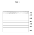
- FIG. 3 is a cross-sectional view showing an organic light emitting diode (“OLED”) display according to an embodiment.
- OLED organic light emitting diode
- an organic light emitting diode (“OLED”) display includes a base substrate 410 , a lower electrode 420 , an organic emission layer 430 , an upper electrode 440 , an encapsulation substrate 450 , a compensation film 460 , and a polarization film 470 .
- the base substrate 410 may be formed of glass or plastic.
- Either of the lower electrode 420 and the upper electrode 440 may be an anode, while the other is a cathode.
- the anode is an electrode where holes are injected, and is formed of a transparent conductive material having a high work function and externally transmitting entered light, for example, ITO or IZO.
- the cathode is an electrode where electrons are injected, is formed of a conducting material having a low work function and having no influence on an organic material, and is selected from, for example, aluminum (Al), calcium (Ca), and barium (Ba).
- the organic emission layer 430 includes an organic material emitting light when a voltage is applied between the lower electrode 420 and the upper electrode 440 .
- auxiliary layer may be included between the lower electrode 420 and the organic emission layer 430 and between the upper electrode 440 and the organic emission layer 430 .
- the auxiliary layer may include a hole transport layer for balancing electrons and holes, a hole injection layer (“HIL”), an electron injection layer (“EIL”), and an electron transport layer.
- HIL hole injection layer
- EIL electron injection layer
- the encapsulation substrate 450 may be made of glass, metal, or a polymer.
- the lower electrode 420 , the organic emission layer 430 , and the upper electrode 440 are sealed to prevent moisture and/or oxygen from externally flowing in.
- the compensation film 460 may circularly polarize light passing through the polarization film 470 and generate a phase difference, and thus have an influence on reflection and absorption of the light.
- the compensation film 460 may be, for example, a phase difference film such as ⁇ /4 plate, and may be omitted depending on the case.
- the polarization film 470 may be disposed at a light-emitting side.
- the polarization film 470 may be disposed outside of the base substrate 410 in a bottom emission type in which light emits from the base substrate 410 , and outside of the encapsulation substrate 450 in a top emission type in which light emits from the encapsulation substrate 450 .
- the polarization film 470 is the same as described above.
- the compensation film 460 and polarization film 470 may be disposed at a display screen of an organic light emitting diode (“OLED”) display and thus may play a role of an antireflective film preventing reflection of light flowing in from the outside.
- the antireflective film may prevent visibility deterioration due to the light flowing in from the outside.
- the 1 H NMR analysis result is as follows.
- the yield of the compound is 45%.
- the structure of the monoazo compound is analyzed through 1 H NMR.
- the 1 H NMR analysis result is as follows.
- the structure of the dichroic dye represented by the above Chemical Formula 1a is analyzed through 1 H NMR.
- the 1 H NMR analysis result is as follows.
- a dichroic dye represented by the following Chemical Formula 1b is prepared according to the same method as Synthesis Example 1, except for using N,N,3-trimethylaniline instead of the N,N-dimethylnaphthalene-1-amine.
- the yield of the dichroic dye is 71%.
- the structure of the dichroic dye represented by the above Chemical Formula 1b is analyzed through 1 H NMR.
- the 1 H NMR analysis result is as follows.
- dichroic dye represented by the following Chemical Formula 1c is obtained according to the same method as Synthesis Example 1, except for using 6-octyl-1,3-benzothiazole-2-amine instead of the 6-octyloxy-1,3-benzothiazole-2-amine.
- the yield of the dichroic dye is 62%.
- the structure of the dichroic dye represented by the above Chemical Formula 1c is analyzed through 1 H NMR.
- the 1 H NMR analysis result is as follows.
- a dichroic dye represented by the following Chemical Formula 1d is prepared according to the same method as Synthesis Example 1, except for using 1,3-benzothiazole-2-amine instead of the 6-octyloxy-1,3-benzothiazole-2-amine.
- the yield of the dichroic dye is 67%.
- the structure of the dichroic dye represented by the above Chemical Formula 1d is analyzed through 1 H NMR.
- the 1 H NMR analysis result is as follows.
- a commercially-available dichroic dye represented by the following Chemical Formula 1e is used (Showa Chem., Japan).
- the solubility parameters are Hildebrand solubility parameters.
- cohesive energy Intermolecular cohesion occurs by a combination of Van der Waals and dipole moments inside molecules, and energy causing such cohesion is referred to as cohesive energy (“Ecoh”).
- cohesive energy may be changes of internal energy per 1 mole, and may be represented by the following Relationship Equation 1.
- ⁇ U is changes of internal energy per mole
- ⁇ H is enthalpy changes
- ⁇ T is temperature changes.
- Cohesive energy per unit volume may be defined as cohesive energy density (“CED”), which may be obtained by the following Relationship Equation 2.
- CED ( ⁇ H ⁇ RT )/ Vm Relationship Equation 2
- CED is a cohesive energy density
- R is a constant
- T is a temperature
- Vm is a mole volume
- the cohesive energy density is used to define the Hildebrand solubility parameter that numerically indicates dissolution performance, and the solubility parameter may be calculated by the following Relationship Equation 3 using a density or mole volume at a predetermined temperature.
- ⁇ is a solubility parameter
- CED is a cohesive energy density
- Ecoh i is cohesive energy for a functional group i inside a molecule
- Vm i is a mole volume
- Hildebrand solubility parameter values used for designing a structure of a dichroic dye may be calculated by group contribution of molecules.
- a composition for a polarization film is prepared by mixing a polyolefin (solubility parameter: 16.6) including polypropylene (“PP”) and a polypropylene-polyethylene copolymer (“PP-PE”) in a ratio of 5:5 (weight/weight), and 0.5 parts by weight of the dichroic dye according to the Synthesis Example 1, based on 100 parts by weight of the polyolefin.
- a polyolefin solubility parameter: 16.6
- PP polypropylene
- PP-PE polypropylene-polyethylene copolymer
- the composition for a polarization film is melt-blended at about 250° C. using a micro-compounder (“DSM”).
- DSM micro-compounder
- the melt blend is put in a sheet mold and pressed at a high temperature and a high pressure, manufacturing a film.
- the film is elongated 1,000% in a uniaxial direction (Instron Ltd.) at 125° C., manufacturing a polarization film.
- a polarization film is manufactured according to the same method as Example 1, except for using the dichroic dye according to Synthesis Example 2 instead of the dichroic dye according to Synthesis Example 1.
- a polarization film is manufactured according to the same method as Example 1, except for using the dichroic dye according to Synthesis Example 3 instead of the dichroic dye according to Synthesis Example 1.
- a polarization film is manufactured according to the same method as Example 1, except for using the dichroic dye according to Comparative Synthesis Example 1 instead of the dichroic dye according to Synthesis Example 1.
- a polarization film is manufactured according to the same method as Example 1, except for using the dichroic dye according to Comparative Synthesis Example 2 instead of the dichroic dye according to Synthesis Example 1.
- Polarization efficiency and dichroic ratio are obtained using transmittance.
- the transmittance is evaluated by respectively measuring light transmittance of light entering parallel to the transmissive axis of the polarization film and light transmittance of light entering perpendicular to the transmissive axis of the polarization film.
- the transmittance is used to calculate a dichroic ratio (“DR”) and polarization efficiency (“PE”).
- DR dichroic ratio
- PE polarization efficiency
- DR The dichroic ratio
- DR denotes a dichroic ratio
- T // is transmittance of polarization film regarding light parallel to the transmissive axis of a polarization film
- T ⁇ is transmittance of polarization film regarding light perpendicular to the transmissive axis of the polarization film.
- PE denotes polarization efficiency
- T // is transmittance of polarization film regarding light parallel to the transmissive axis of a polarization film
- T ⁇ is transmittance of polarization film regarding light perpendicular to the transmissive axis of the polarization film.
- FIG. 4 is a graph showing dichroic ratios in a visible ray region according to the polarization films according to Examples 1 to 3 and Comparative Examples 1 and 2.
- the polarization films according to Examples 1 to 3 show higher polarization efficiency and dichroic ratios than those of Comparative Examples 1 and 2.
Abstract

Description


DR=Log(1/T ⊥)/Log(1/T //)

DR=Log(1/T ⊥)/Log(1/T //)
PE(%)=[(T // −T ⊥)/(T // −T ⊥)]1/2×100


Evaluation 1: Solubility Parameter
E coh =ΔU=ΔH−ΔT
CED=(ΔH−RT)/
δ=(CED)0.5=(ΣEcohi /ΣVm i)0.5 Relationship Equation 3
| TABLE 1 | ||||
| Group | Ecoh (J/mol) | Vm (cm3/mol) | ||
| —CH3 | 4707 | 33.5 | ||
| —CH2— | 4937 | 16.1 | ||
| —CH— | 3431 | −1.0 | ||
| C | 1464 | −19.2 | ||
| H2C═ | 4310 | 28.5 | ||
| —CH═ | 4310 | 13.5 | ||
| C═ | 4310 | −5.5 | ||
| Phenyl | 31924 | 71.4 | ||
| Phenylene (o, m, p) | 31924 | 52.4 | ||
| Phenyl (trisubstituted) | 31924 | 33.4 | ||
| Phenyl (tetrasubstituted) | 31924 | 14.4 | ||
| Phenyl (pentasubstituted) | 31924 | −4.6 | ||
| Phenyl (hexasubstituted) | 31924 | −23.6 | ||
| Ring closure 5 or more atoms | 1046 | 16.0 | ||
| Ring closure 3 or 4 atoms | 3138 | 18.0 | ||
| —COOH | 27614 | 28.5 | ||
| —CO2— | 17991 | 18.0 | ||
| —CO— | 17364 | 10.8 | ||
| —CONH— | 33472 | 9.5 | ||
| —NH2 | 12552 | 19.2 | ||
| —NH— | 8368 | 4.5 | ||
| N | 4184 | −9.0 | ||
| —N═ | 11715 | 5.0 | ||
| —N═N— | 4188 | 0.0 | ||
| —CN | 25522 | 24.0 | ||
| NO2 | 15355 | 32.0 | ||
| —O— | 3347 | 3.8 | ||
| —OH | 29790 | 10.0 | ||
| S | 14142 | 12.0 | ||
| —F | 4184 | 18.0 | ||
| —Cl | 11548 | 24.0 | ||
| —Br | 15481 | 30.0 | ||
| —I | 19037 | 31.5 | ||
| TABLE 2 | ||
| Solubility parameter | ||
| Synthesis Example 1 | 24.0 | ||
| Synthesis Example 2 | 22.5 | ||
| Synthesis Example 3 | 23.9 | ||
| Comparative Synthesis Example 1 | 26.5 | ||
| Comparative Synthesis Example 2 | 27.1 | ||
Manufacturing Polarization Film
DR=Log(1/T ⊥)/Log(1/T //)
PE(%)=[(T // −T ⊥)/(T // −T ⊥)]1/2×100
| TABLE 3 | |||||
| Polarization | Dichroic | Solubility parameter | |||
| λmax | efficiency | ratio | difference | ||
| (nm) | (PE, %) | (DR) | (dye − polyolefin) | ||
| Example 1 | 500 | 98.65 | 3.1 | 7.4 |
| Example 2 | 465 | 97.78 | 3.3 | 5.9 |
| Example 3 | 505 | 96.58 | 3.0 | 7.3 |
| Comparative | 505 | 25.59 | 1.2 | 9.9 |
| Example 1 | ||||
| Comparative | 620 | 23.12 | 1.3 | 10.5 |
| Example 2 | ||||
Claims (16)


DR=Log(1/T ⊥)/Log(1/T //) Equation 1
Applications Claiming Priority (2)
| Application Number | Priority Date | Filing Date | Title |
|---|---|---|---|
| KR10-2013-0054491 | 2013-05-14 | ||
| KR1020130054491A KR102057722B1 (en) | 2013-05-14 | 2013-05-14 | Composition for polarizing film and polarizing film and display device |
Publications (2)
| Publication Number | Publication Date |
|---|---|
| US20140339482A1 US20140339482A1 (en) | 2014-11-20 |
| US9798057B2 true US9798057B2 (en) | 2017-10-24 |
Family
ID=51895057
Family Applications (1)
| Application Number | Title | Priority Date | Filing Date |
|---|---|---|---|
| US14/244,145 Active 2035-10-16 US9798057B2 (en) | 2013-05-14 | 2014-04-03 | Composition for polarization film, polarization film, and display device |
Country Status (2)
| Country | Link |
|---|---|
| US (1) | US9798057B2 (en) |
| KR (1) | KR102057722B1 (en) |
Families Citing this family (2)
| Publication number | Priority date | Publication date | Assignee | Title |
|---|---|---|---|---|
| JP2016118782A (en) | 2014-12-17 | 2016-06-30 | 三星電子株式会社Samsung Electronics Co., Ltd. | Polarizing film and display device including the same |
| KR102167219B1 (en) * | 2017-02-10 | 2020-10-19 | 주식회사 엘지화학 | Resin composition for polarizing plate |
Citations (7)
| Publication number | Priority date | Publication date | Assignee | Title |
|---|---|---|---|---|
| JPS5784409A (en) | 1980-11-15 | 1982-05-26 | Toyobo Co Ltd | Polarizing film |
| JPH11101964A (en) * | 1997-08-01 | 1999-04-13 | Sony Corp | Polarization element and display device |
| JP2007316617A (en) * | 2006-04-26 | 2007-12-06 | Konica Minolta Holdings Inc | Polarizing film |
| JP2009217012A (en) | 2008-03-11 | 2009-09-24 | Osaka Prefecture Univ | Polypropylene polarizing plate |
| JP2010101983A (en) | 2008-10-22 | 2010-05-06 | Konica Minolta Opto Inc | Polarizing film, method of manufacturing polarizing film, and liquid crystal display device using the film |
| JP2011150162A (en) | 2010-01-22 | 2011-08-04 | Showa Kako Kk | Polarizing plate and method for producing the same |
| US20120050652A1 (en) * | 2010-08-30 | 2012-03-01 | Samsung Electronics Co., Ltd. | Composition for polarizing film, polarizing film, method of manufacturing the same, and liquid crystal display provided with the polarizing film |
Family Cites Families (1)
| Publication number | Priority date | Publication date | Assignee | Title |
|---|---|---|---|---|
| JP2008052170A (en) | 2006-08-28 | 2008-03-06 | Konica Minolta Holdings Inc | Polarization film, method for manufacturing polarization film, and polarization plate and liquid crystal using the same |
-
2013
- 2013-05-14 KR KR1020130054491A patent/KR102057722B1/en active IP Right Grant
-
2014
- 2014-04-03 US US14/244,145 patent/US9798057B2/en active Active
Patent Citations (7)
| Publication number | Priority date | Publication date | Assignee | Title |
|---|---|---|---|---|
| JPS5784409A (en) | 1980-11-15 | 1982-05-26 | Toyobo Co Ltd | Polarizing film |
| JPH11101964A (en) * | 1997-08-01 | 1999-04-13 | Sony Corp | Polarization element and display device |
| JP2007316617A (en) * | 2006-04-26 | 2007-12-06 | Konica Minolta Holdings Inc | Polarizing film |
| JP2009217012A (en) | 2008-03-11 | 2009-09-24 | Osaka Prefecture Univ | Polypropylene polarizing plate |
| JP2010101983A (en) | 2008-10-22 | 2010-05-06 | Konica Minolta Opto Inc | Polarizing film, method of manufacturing polarizing film, and liquid crystal display device using the film |
| JP2011150162A (en) | 2010-01-22 | 2011-08-04 | Showa Kako Kk | Polarizing plate and method for producing the same |
| US20120050652A1 (en) * | 2010-08-30 | 2012-03-01 | Samsung Electronics Co., Ltd. | Composition for polarizing film, polarizing film, method of manufacturing the same, and liquid crystal display provided with the polarizing film |
Non-Patent Citations (2)
| Title |
|---|
| Fedors, Robert F., "A Method for Estimating Both the Solubility Parameters and Molar Volumes of Liquids," Polymer Engineering and Science, Feb. 1974, vol. 14, No. 2, pp. 147-154. |
| Karst, et al, "Using the Solubility Parameter to Explain Disperse Dye Sorption on Polylactide," Journal of Applied Polymer Science vol. 96, p. 416-422, (2005). |
Also Published As
| Publication number | Publication date |
|---|---|
| KR20140134510A (en) | 2014-11-24 |
| US20140339482A1 (en) | 2014-11-20 |
| KR102057722B1 (en) | 2019-12-19 |
Similar Documents
| Publication | Publication Date | Title |
|---|---|---|
| JP6636077B2 (en) | Polarizing film and display device | |
| EP2728388B1 (en) | Anti-reflective film and display device | |
| US20130303677A1 (en) | Composition for polarizing film, polarizing film, and display device including the polarizing film | |
| US9207359B2 (en) | Polarizing film and display device including the polarizing film | |
| US9791609B2 (en) | Polarization film and display device | |
| US10018761B2 (en) | Compensation film and method of manufacturing the same | |
| US9798057B2 (en) | Composition for polarization film, polarization film, and display device | |
| US8679376B2 (en) | Dichroic dye for use in polarizing film, polarizing film, and display device including the polarizing film | |
| US9207361B2 (en) | Composition for polarizing film, and polarizing film and display device | |
| US9335442B1 (en) | Polarizing film and display device including the polarizing film | |
| US20230273361A1 (en) | Optically anisotropic film, circularly polarizing plate, and display device | |
| US9927555B2 (en) | Composition for polarizing film, polarizing film, and display device | |
| US20160187548A1 (en) | Polarizing film and display device including the polarizing film | |
| US9268065B1 (en) | Composition for polarizing film, polarizing film, and display device including the polarizing film | |
| JP7457794B2 (en) | Composition, optically anisotropic film, circularly polarizing plate, display device | |
| KR20180023655A (en) | Polarizing Element and use thereof |
Legal Events
| Date | Code | Title | Description |
|---|---|---|---|
| AS | Assignment |
Owner name: KYUNGPOOK NATIONAL UNIVERSITY INDUSTRY-ACADEMIC CO Free format text: ASSIGNMENT OF ASSIGNORS INTEREST;ASSIGNORS:LEE, YONG JOO;MOON, DEUK KYU;PARK, SANG HO;AND OTHERS;REEL/FRAME:032595/0572 Effective date: 20140303 Owner name: SAMSUNG ELECTRONICS CO., LTD., KOREA, REPUBLIC OF Free format text: ASSIGNMENT OF ASSIGNORS INTEREST;ASSIGNORS:LEE, YONG JOO;MOON, DEUK KYU;PARK, SANG HO;AND OTHERS;REEL/FRAME:032595/0572 Effective date: 20140303 |
|
| STCF | Information on status: patent grant |
Free format text: PATENTED CASE |
|
| MAFP | Maintenance fee payment |
Free format text: PAYMENT OF MAINTENANCE FEE, 4TH YEAR, LARGE ENTITY (ORIGINAL EVENT CODE: M1551); ENTITY STATUS OF PATENT OWNER: LARGE ENTITY Year of fee payment: 4 |