BACKGROUND
Field
The invention relates to robotic sensing systems and methods of controlling and operating the robotic sensing systems, and more particularly to systems and methods for tactile sensing.
Description of the Related Art
With the increasing popularity of robotic devices in industrial and personal use applications, sensing the surrounding environment has become ever important. Many robotic devices generally interact with objects in their surrounding environment. If the robotic devices contact these objects in an improper manner, the robotic device and/or the object can be damaged or broken. For example, if a robotic device grabs a glass too quickly, the glass may break. Therefore, it is ideal for robotic devices to detect an object before the object comes into contact with the robotic device. This early or prior detection allows the robotic device to anticipate the impending contact and have additional time to react to the object.
Furthermore, traditional sensing systems of robotic devices that have the capability of sensing an object near a robotic device are expensive, bulky and complex. In certain applications, robotic devices have relatively large surface areas that may be exposed to an impending contact. Placement of numerous expensive sensors over the surface areas is cost-prohibitive and not feasible. In addition, when each sensor generates a different set of data, analysis and processing of such a large collection of data becomes overly complex and cause significant time delays.
Hence, there is a need in the art for an accurate and efficient, yet cost-effective and non-complex, object sensing solution to acquire a general tactile understanding of relatively large surface areas of the robotic device that are expected to contact an object. Furthermore, there is a need for an object sensing solution that simplifies tactile data sensing and analysis in order to allow the robotic device to react quickly and in real-time to the impending contact.
SUMMARY
The invention relates to a tactile fur sensing system and a method of controlling and operating thereof that allow sensing an impending contact between a surface of a robotic device and an object before the object contacts the surface. The tactile fur sensing system provides a cost-effective solution to advantageously gain a tactile understanding of a surface area upon which a plurality of filaments, threads, and/or nubs are positioned.
According to an aspect of the invention, a robotic sensing system includes a first plurality of filaments or threads positioned on a first zone or area of a surface. A first sensor is connected to the first plurality of filaments or threads. The first sensor is configured to detect first sensor data corresponding to at least one of a first electrical resistance value or a first displacement of the first plurality of filaments or threads. A processor is communicatively coupled to first sensor. The processor is configured to determine a first contact between the first plurality of elements or threads with a first object prior to contact of the first object with the first zone or area of the surface based on the first sensor data.
According to another aspect of the invention, a robotic sensing system is provided, having a plurality of nubs or elements positioned on a surface area. Each nub or element is configured to be flexible in order to be displaced upon contact with an object. Each nub or element includes an outer cast or protection layer defining a cavity therein. A sensor is configured to detect a displacement of the nub or element, with at least one part of the sensor positioned in the cavity of the outer cast or protection layer. The outer cast or protection layer prevents contact between the sensor and an object outside the cavity. A processor is communicatively coupled to the sensor, and configured to determine that at least one part of the surface area is in contact with the object based on the detected displacement.
The sensor may be a pressure-based sensor configured to generate a signal when a pressure applied to the outer cast or protection layer exceeds a force or pressure threshold. The part of the sensor that is positioned in the cavity includes a first electrical contact and a second electrical contact. The sensor is configured to generate a signal when the first electrical contact is connected to the second electrical contact, which occurs when sufficient pressure is applied to the outer cast or protection layer.
According to yet another aspect of the invention, a method for detecting an impending contact between a robotic device and an object is provided. A plurality of filaments or threads are positioned on a zone or area of a surface of a robotic device. A baseline value is stored in a memory. The baseline value corresponds to at least one of a baseline resistance value detected by the sensor or a rate or amount of change in the resistance value. The baseline value is determined when the plurality of filaments or threads are in a first position and without contact with an object. A sensor connected to a plurality of filaments or threads detects the resistance value corresponding to the plurality of filaments or threads. A processor determines a first contact with a first object based on the detected resistance value and the stored baseline value. The processor resets the baseline value when or after the plurality of filaments or threads are in a steady state position without contact with an object. The processor utilizes the detected resistance value and the reset baseline value for determining whether there is a second contact with the first object or a second object.
The systems and methods of the invention provide an economical solution for effective, efficient and early detection of an impending contact between a robotic device and an object.
BRIEF DESCRIPTION OF THE DRAWINGS
Other systems, methods, features, and advantages of the present invention will be apparent to one skilled in the art upon examination of the following figures and detailed description. Component parts shown in the drawings are not necessarily to scale, and may be exaggerated to better illustrate the important features of the present invention, wherein:
FIG. 1 is a block diagram of a tactile sensing system according to an aspect of the invention;
FIG. 2A is a schematic view of a plurality of non-overlapping zones or area of a robotic surface, each having a plurality of filaments or threads for robotic sensing, according to an aspect of the invention;
FIG. 2B is a schematic view of a plurality of overlapping zones or area of a robotic surface, each having a plurality of filaments or threads for robotic sensing, according to an aspect of the invention;
FIG. 2C is a schematic view of a robotic arm having at least one patch of sensing fur according to an aspect of the invention;
FIG. 3A is a schematic side view of a woven conductive yarn connected to a sensor according to an aspect of the invention;
FIG. 3B is a schematic view of a woven conductive yarn according to an aspect of the invention;
FIG. 3C is a schematic view of a strand of conductive yarn connected to a sensor according to an aspect of the invention;
FIG. 3D is a schematic view of a strand of conductive yarn wrapped around a robotic arm according to an aspect of the invention;
FIG. 4A is a schematic side view of a plurality of nubs or elements for object sensing according to an aspect of the invention;
FIG. 4B is a schematic isometric view of a plurality of nubs or elements positioned on a surface for object sensing according to an aspect of the invention;
FIG. 4C is a schematic isometric view of a sensor positioned inside a cavity of a nub or an element according to an aspect of the invention;
FIG. 5 is a flowchart diagram of a method for detecting an object contacting a plurality of filaments or threads positioned on a zone or area of a surface of a robotic device according to an aspect of the invention; and
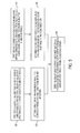
FIG. 6 is a flowchart diagram of a method for detecting an object contacting a plurality of filaments or threads positioned on a zone or area of a surface of a robotic device based on a reset baseline value according to an aspect of the invention.
DETAILED DESCRIPTION
The invention relates to tactile fur sensing systems and methods that can detect an object that is in close proximity to a device (such as a robotic device). An impending contact is detected prior to physical contact between the object and the robotic device. In certain embodiments, the tactile fur sensing system includes one or more conductive filaments or threads arranged in a zone or area of a surface of the robotic device. When an object contacts the filaments or threads, they are displaced and resistance across the plurality of filaments or threads changes. The displacement and/or resistance value can be detected by one or more sensors. This advantageously allows a processor communicatively coupled to the sensors to detect the proximity of an object. In other embodiments, nubs or elements are provided, each having an outer cast or protective layer. At least a part of a sensor is positioned in a cavity defined in the outer cast or protective layer. The outer cast or protective layer protects the sensor positioned therein.
The embodiments described herein provide an accurate and efficient, yet cost-effective and non-complex, object sensing solution for acquiring a general tactile understanding of relatively large surface areas of a robotic device and for early detection of an impending contact between an object and a surface of a robotic device, without requiring complex sensing circuitry and/or processing. The object sensing solution also simplifies tactile data sensing and analysis in order to allow the robotic device to react quickly and in real-time to the impending contact. Hence, the robotic sensing systems and methods described herein advantageously provide a more cost-effective, accurate and safe way of interacting with objects. In addition, the early detection advantageously avoids damage or harm to the object or person and increases the accuracy in picking up, moving or interacting with the object or person.
The discussion now turns to interaction of certain elements of the tactile sensing system, as shown in the block diagram of FIG. 1. A first plurality of filaments or threads 106 a are electrically coupled to at least one sensor, such as the first sensor 104 a. The first plurality of filaments or threads 106 a may include conductive or non-conductive filaments, threads, fibers, and/or other elements that can form a fur-like structure when positioned as a group on a surface and can provide sensing feedback upon contact with an object. As a result of a contact with an object, the first plurality of filaments or threads 106 a are displaced. Displacement upon contact with the object results in a change of the electrical resistance across the first plurality of filaments or threads 106 a. The first sensor 104 a is configured to detect first data that corresponds to a first displacement and/or a first electrical resistance value of the first plurality of filaments or threads 106 a.
Similarly, a second plurality of filaments or threads 106 b are electrically coupled to at least one sensor, such as the second sensor 104 b. The second sensor 104 b is configured to detect a second displacement and/or a second electrical resistance value corresponding to the second plurality of filaments or threads 106 b.
A processor 102 is communicatively coupled to the first sensor 104 a and the second sensor 104 b. The processor 102 is configured to analyze first data detected by the first sensor 104 a and the second data detected by the second sensor 104 b to draw an inference about areas of contact with one or more objects. The processor 102 makes this determination based on threshold data and baseline data stored in a memory 116 communicatively coupled to the processor 102.
To illustrate the importance of early detection of contact with the surface, consider an example that a robot seeks to pick up an object with a robotic arm. It is desirable for the robotic arm to avoid physical contact with another object or person because such force may harm the other object or the person. Furthermore, if the robotic arm moves too quickly or the applied force is great enough, the object that is intended to be picked up may be broken or damaged. By early detection of an impending contact, the robotic device may have more time to take action, such as stopping or slowing movement or moving in an opposite direction. In addition, the early detection avoids damage or harm to the object or person and increases the accuracy in picking up, moving or interacting with the object or person.
The processor 102 may be one or more processors of a control unit or a controller of a robotic device positioned remotely. The processor 102 is communicatively coupled to the first sensor 104 a, the second sensor 104 b and/or the memory 116. The memory 116 includes an internal memory of the robotic device. Alternatively or in addition, the memory 116 includes a remote cloud-based memory accessible to the processor 102 via wireless communication. The discussion now turns to an example of the structure and arrangement of the first and the second plurality of filaments or threads 106 a-b.
Referring to FIG. 2A, a tactile fur sensing system 200A (“system 200A”) includes a first plurality of filaments or threads that are positioned as a first patch 214 a on a first zone or area 220 a of a surface 218. The surface 218 may correspond to an outer surface of a robotic device such as a robotic arm. The first patch 214 a is connected to a first sensor 204 a (not shown). The system 200A further includes a second plurality of filaments or threads positioned as a second patch 214 b on a second zone or area 220 b of the surface 218. The second patch 214 b is connected to a second sensor 204 b (not shown).
In a preferred embodiment, the filaments or threads are electrically conductive. Alternatively, non-conductive filaments or threads may also be used. The first patch 214 a and/or the second patch 214 b may have a fur texture. The texture is compliant such that the filaments or threads may not return to their original position or orientation after sufficient contact with an object. For example, each of the first plurality of filaments or threads of the first patch 214 a has a certain angle as compared with the surface 218 before contact with an object. After contact with an object, each filament or thread that had sufficient contact with the object may have a substantially different angle as compared with the surface 218 after contact with the object.
It is desirable to have filaments or threads that are long enough to detect contact with an object before the object contacts the surface of the robotic device. However, the rigidity of the filaments or threads would decrease as the length of the filaments or threads is increased. It is desirable for the filaments or threads to be rigid enough to be in a position to influence or be influenced by the object before the object contacts the surface of the robotic device. As such, the length is designed to be long enough to contact the object while maintaining a minimum level of rigidity. The length of the filaments or threads of a given patch can be uniform across a given patch, or may vary across a given patch, depending on design parameters. The length of filaments or threads of a given patch (e.g., first patch 214 a) may be the same as or different from the length of filaments or threads of another patch (e.g., second patch 214 b). The length of the filaments or threads may vary based on the location of the zone or area upon which the filaments or threads are positioned and/or expected distance with an object. If the patch is located in open space in an area expected to receive contact forces in different directions, a greater level of rigidity would be desirable. More compliant filaments or threads can be used if the patch is located on a surface that is rested vertically up or down and the direction of contact forces are expected to be relatively uniform.
The filaments or threads of the first patch 214 a and/or the second patch 214 b may be arranged to have similar density and length of, for example, a toothbrush. A given millimeter square of a zone or area of the surface 218 may have between 8 and 12 filaments or threads. The length of an extension of each filament or thread from the surface 218 may be at least 7 millimeters long.
In the preferred embodiment, each of the first patch 214 a and/or the second patch 214 b is connected to one sensor in order to gain a tactile understanding of a zone or area of the surface 218 without utilizing a high number of sensors. This may also advantageously reduce the complexity of sensing, processing and/or analysis in order to provide an earlier tactile understanding. As discussed above, an early tactile understanding can advantageously allow the robotic device to prepare for and/or react to an impending contact. In other embodiments, one or more of the patches can each be connected to more than one sensor.
The discussion now turns to an example of operation of the system 100 or 200 discussed above. The first sensor 104 a detects first sensor data for a first zone or area 220 a of the surface 218 (see also step 502 of FIG. 5). The first sensor data may correspond to a first electrical resistance value or a first displacement of a first plurality of filaments or threads. For example, first sensor 104 a may be a resistance-based sensor that detects a first electrical resistance value. The first electrical resistance value may correspond to resistance sensed across the first patch 214 a.
The first sensor 104 a may be a pressure-based sensor configured to generate a signal when a pressure applied to the first patch 214 a exceeds a pressure threshold. Alternatively, the first sensor 104 a may be a pressure-based and resistance-based sensor. Once enough pressure is applied and the switch is closed, the resistance value is determined for determining the type of contact. The second sensor 104 b detects second sensor data for a second zone or area 220 b of the surface 218 (see also step 504). The second sensor data may correspond to a second electrical resistance value and/or a second displacement of a second plurality of filaments or threads of a second patch 214 b.
The processor 102 determines whether there is a first contact between the first plurality of elements or threads of a first patch 214 a with a first object based on the first sensor data (see also step 506). In the embodiment that the first sensor 104 a is a resistance-based sensor, the processor 102 may determine that the first contact is established prior to contact of the first object with the first zone or area 220 a based on the first electrical resistance value and an electrical resistance threshold value stored in the memory 116.
Not every change in resistance value corresponds to a contact with an object. Resistance value can change when there is a change in environmental conditions (such as wind that causes bending of the filaments or threads) or due to movement of the robotic device or part. Resistance values can also change if there is contact with another part of the robotic device. A range of resistance values during contact with an object may be stored in the memory 116. The processor 102 is configured to determine that there is contact with an object when the sensed resistance value falls within the range of resistance values. Alternatively or in addition, a range of rates of change in the resistance values can be stored such that the processor 102 can determine whether the detected change in resistance value indicates a certain type of contact. For example, the absolute value of rate or amount of change in resistance may be greater for contacts with an object as compared with contacts with another part of the robotic device and even further different as compared with mild fluctuations due to environmental conditions.
The stored threshold values may correspond to lower and upper bounds of resistance values or rates of changes in resistance values that correspond to a contact with an object. Threshold values, ranges of resistance values, and/or ranges of rates of change in resistance values can be stored in the memory 116, in order to effectively determine whether there is contact and determine the type of contact. The processor 102 may further update the stored threshold values, ranges of resistance values, and/or ranges of rates of change in resistance values based on data collected regarding a contact with an object. The updated threshold values, ranges of resistance values, and/or ranges of rates of change in resistance values can be utilized for detecting and distinguishing types of future contacts.
In the embodiment that the first sensor 104 a is a pressure-based sensor, contact with an object can be detected when the pressure exceeds a certain pressure threshold value stored in the memory 116. Alternatively, a switch may be used without detection of a number or value. The first sensor 104 a may have a switch that would close when the pressure exceeds a threshold value, and as a result, the first sensor 104 a would generate a signal. In such an embodiment, the first sensor data can be a binary value, corresponding to either the switch being closed or open. The processor 102 determines that there is contact of an object with the first patch 214 a when the switch is closed and the corresponding signal is received from the first sensor 104 a. Similar to the process set forth above, the processor 102 can determine a second contact between the second plurality of elements or threads with the first object or a second object based on the second sensor data (see also step 508).
Although two sets of sensor data and two zones or areas are discussed above, impending contact with additional zones or areas can be determined as discussed below, for example, with respect to FIG. 2B. The processor 102 determines areas of contact between one or more objects and the surface 218 before the one or more objects contact the surface 218. The determination is based on the first sensor data, the second sensor data, and/or additional sensor data (see also step 510).
Using the method described above, proximity of an object to a relatively large area of a surface of a robotic device can be effectively determined in a cost-effective manner. Data regarding each zone or area can be put together to obtain a map of areas of contacts and optionally types of contacts. This advantageously provides a tactile understanding of a relatively large surface area without use of complex sensors. Specific localization of points of contact may not be obtained and is not necessary. Use of complex sensing devices and/or processing would not be necessary either. Rather, a general understanding of areas of contact with an object can be determined prior to contact with an object.
The discussion now turns to a method of determining contact with an object based on an adjustable baseline value. A first patch (e.g., the first patch 214 a) is connected to a resistance-based sensor (e.g., the first sensor 104 a). A baseline value for the first sensor 104 a may be initially stored in the memory 116. The baseline value may correspond to a baseline resistance value and/or an amount or rate of resistance change (see also step 602 of FIG. 6). The baseline value may correspond to an initial condition in which the first patch 214 a has not yet contacted other objects.
As discussed above, a threshold value or a range of resistance values with upper and lower boundaries defined by threshold resistance values may be stored in the memory 116. The one or more threshold resistance values distinguish between no contact, contact with another part of the robotic device, or contact with an exterior object (see also step 604).
The first sensor 104 a detects a first resistance value corresponding to the first plurality of filaments or threads of the first patch 214 a (see also step 606). The processor 102 is configured to analyze the detected first resistance value and/or the rate of change in the resistance value based on the stored one or more threshold resistance values. Considering the scenario in which a first object contacts the first patch 214 a, the processor 102 determines that there is a first contact with the first object (see also step 608). The processor 102 reaches this determination by comparing the resistance value and/or the change in the resistance value to the stored one or more threshold resistance values.
Before contact with the object, the first plurality of filaments or threads of the first patch 214 a are in a first position or orientation. The filaments or threads that contact the object may change position or orientation. In other words, the filaments or threads would not return to their original position or orientation, and therefore, would not exhibit the same resistance value that they did prior to contact with the object. The change in measurement of resistance value may lead to inaccuracy for future detection of contact. To prevent or substantially reduce the inaccuracy, the processor 102 resets the baseline value based on a resistance value that is sensed in a steady state condition. In order to reset the resistance value, the processor 102 may first determine that the plurality of filaments or threads are in a steady state condition (see also step 610). The steady state condition may correspond to a condition after contact with the object, and when there is no further contact between the first patch 214 a and an object. During the steady state condition, the processor 102 resets the baseline value (see also step 612). A subsequent second contact between the plurality of filaments or threads and the first object or a second object can be determined by analyzing a second detected resistance value based on the reset baseline value and the resistance threshold values (see also step 614).
Although the foregoing method is described with respect to a resistance-based sensor, a similar process can be applied to pressure-based sensors to reset or re-adjust the baseline values after contact with an object.
In the embodiments discussed above with respect to FIGS. 1 and 2A, only two sets of filaments or threads were described. Alternatively, the invention can be extended to include additional sets of filaments or threads, each having one or more sensors to provide a tactile understanding of contacts with the surface of the robotic device.
In the embodiment shown in FIG. 2A, the first and second plurality of filaments or threads are each arranged as non-overlapping patches 214 a-b. As illustrated in FIG. 2B, two or more patches may have overlapping portions. Each of the first, second, and third plurality of filaments or threads are arranged as a first patch 214 a, a second patch 214 b and a third patch 214 c, respectively. The first, second, and third patches 214 a-c cover a first, second, and third zone or area 220 a, 220 b, and 220 c, respectively. A fourth and a fifth plurality of filaments or threads are arranged as a fourth and fifth patch 214 d and 214 e, respectively. The fourth and fifth patches 214 d and 214 e cover a fourth and fifth zone or area 220 d and 220 e, respectively. Each of the first, second, and third patches 214 a-c has parts that overlap with the fourth and fifth patches 214 d and 214 e. The crisscross pattern of the patches 214 a-e advantageously allows a two-dimensional understanding of contacts with a relatively large area of the surface 218.
This embodiment may have certain advantages to an embodiment in which the same area that patches 214 a-e cover was instead covered by a continuously positioned plurality of filaments or threads. It may allow a relatively higher degree of localization because if both the second patch 214 b and the fifth patch 214 e detect contact with an object, it can be ascertained that there is contact at least in area indicated by “A1.” It may also be more cost-effective to manufacture patches of filaments as strips that can then be positioned in desired patterns with overlapping regions. Furthermore, the overlapping regions may provide additional feedback because, for example, in the overlapping area “A1” a first resistance may be detected by the second patch 214 b and a different resistance may be detected by the fifth patch 214 e. For example, the object may contact filaments or threads of one patch more than the other. The two different inputs for the same area can serve as additional feedback for the overlapping regions to enhance detection of an impending contact.
In another embodiment, the areas of interest for detection, such as the areas covered by patches 214 a-e can be covered by a combination of non-overlapping group of patches, or a continuous larger patch.
FIG. 2C shows a first patch 214 a positioned on a first zone or area of the surface 218 of a robotic arm 212. The first patch 214 a includes a first plurality of filaments or threads 206 a. The detected resistance value across the first plurality of filaments or threads 206 a and/or its rate or amount of change would change upon contact with an object 210. Additional patches may be positioned on the robotic arm 212 as discussed above and as shown, for example, in FIGS. 2A and 2B.
Alternatively, one or more of the patches 214 a-e may be a woven conductive yarn, as discussed in more details with respect to FIGS. 3A-3D.
Referring to FIG. 3A, a yarn 308 a may be positioned on or around a robotic device. The yarn 308 a may be a group of conductive fibers that are woven together. The yarn 308 a can be connected to a first sensor 304 a configured to detect a resistance from one corner to another corner of the yarn 308 a. Alternatively, resistance across other parts of the yarn can be detected.
Referring to FIG. 3B, the yarn 308 a may advantageously have a cylindrical shape to properly or snugly fit around a robotic arm. The yarn 308 a can be positioned, for example, around a robotic arm. Certain conductive fibers 306 a of the yarn 308 a are designed such they are sufficiently “fuzzy” in order to ensure that the conductive fibers 306 a extrude radially outward to contact an object. Upon contact with the conductive fibers 306 a, the resistance value of the yarn 308 a changes upon contact.
Referring to FIG. 3C, a strand of yarn 308 b made of woven conductive fibers 306 b is connected to a sensor 304 b. The sensor 304 b is configured to detect resistance across the strand of yarn 308 b. As shown in FIG. 3D, one or more strands of yarn (such as strand of yarn 308 b) can be wrapped around the robotic arm 312 in order to detect contact with an object 310.
In the embodiments described above, the filaments or threads and/or the fibers of the yarns were in direct contact with an object. Alternatively, a robotic device may be positioned in an environment in which filaments or threads can be severely damaged, thereby affecting the accuracy of detection. In such conditions, a plurality of nubs with an outer casting or protective layer may be utilized to prevent damage to sensing devices.
Referring to FIG. 4A, a plurality of nubs 430 may be utilized for detecting contact with an object. A “nub” as used herein refers to an element that has an outer casting or protective layer. The outer casting or protective layer protects against damage from the environment or objects therein (for example, from liquids or chemicals). The nubs 430 may be waterproof. The plurality of nubs are preferably made of polyurethane. The plurality of nubs 430 are designed to be long enough to interact with an object. The nubs 430 may be configured to detect pressure and generate a signal when the pressure or force exceeds a threshold. The nubs 430 may have a pressure-based sensor within the outer cast that is connected to a reservoir containing a liquid. A force on a nub 430 a would exert certain measurable pressure on the liquid. Alternatively, the pressure-based sensor may be a switch that would be in an on or off state prior to contact. The switch would be in an opposite state upon application of sufficient pressure to the nub, as discussed below with respect to FIG. 4C.
As shown in FIG. 4B, the plurality of nubs 430 may be positioned on a surface 418. The surface 418 may correspond to a surface of a robotic device. The plurality of nubs 430 may be arranged to have similar density and length of, for example, a common toothbrush. A given millimeter square of a zone or area of the surface upon which nubs 430 are placed may have between 8 and 12 nubs. The length of an extension of each nub 430 may be at least 7 millimeters long.
Referring to FIG. 4C, a nub 430 a includes an outer cast or protection layer 432 that defines a cavity 434 therein. The outer case or protection layer 432 may be a relatively thin molded layer. The boundaries of the cavity 434 are shown by dotted lines. A sensor 404 a is provided to detect a displacement of the nub 430 a, with at least one part of the sensor 404 a positioned in the cavity 434. The processor 102 is communicatively coupled to the sensor 404 a, and configured to determine that at least one part of the surface area is in contact with the object based on the detected displacement.
The sensor 404 a may be a pressure-based sensor configured to generate a signal when a pressure applied to the outer cast or protection layer 432 exceeds a pressure threshold. The part of the sensor 404 a that is positioned in the cavity 434 may include a first electrical contact 436 a and a second electrical contact 436 b. The sensor 404 a is configured to generate a signal when the first electrical contact 436 a is connected to the second electrical contact 436 b, which occurs when sufficient pressure is applied to the outer cast or protection layer 432.
Using the methods and systems described above, proximity of an object to a relatively large area of a surface of a robotic device can be effectively determined in a cost-effective manner. By reducing complexity of detection and utilizing relatively long threads or filaments, the robotic device can have adequate time to react to an impending contact due to the early detection.
The described sensing system and method can be advantageously combined with other sensing methods and systems. For example, if certain object is detected using the fur-based system, the processor 102 may control a camera of the robotic device to focus on the object in order to learn more about the object.
The steps described above with respect to FIGS. 5 and 6 may not necessarily be performed in the order presented above. For example, one or more sensors may detect sensor data and a corresponding impending contact may be determined simultaneously, before, and/or after sensing and impending contact determinations for other zones or areas.
While only certain embodiments of the invention have been described in detail, a person skilled in the art would appreciate that certain changes and modifications may be made in the embodiments without departing from the spirit and scope of the invention. A person skilled in the art would appreciate the invention may be practiced other than as specifically described with respect to the foregoing embodiments of the method/system.