US9797236B2 - Logging while drilling electrical imager and method for measurement in oil based mud - Google Patents
Logging while drilling electrical imager and method for measurement in oil based mud Download PDFInfo
- Publication number
- US9797236B2 US9797236B2 US14/305,227 US201414305227A US9797236B2 US 9797236 B2 US9797236 B2 US 9797236B2 US 201414305227 A US201414305227 A US 201414305227A US 9797236 B2 US9797236 B2 US 9797236B2
- Authority
- US
- United States
- Prior art keywords
- transmitters
- receivers
- formation
- vertical
- pair
- Prior art date
- Legal status (The legal status is an assumption and is not a legal conclusion. Google has not performed a legal analysis and makes no representation as to the accuracy of the status listed.)
- Expired - Fee Related, expires
Links
Images


Classifications
-
- E—FIXED CONSTRUCTIONS
- E21—EARTH OR ROCK DRILLING; MINING
- E21B—EARTH OR ROCK DRILLING; OBTAINING OIL, GAS, WATER, SOLUBLE OR MELTABLE MATERIALS OR A SLURRY OF MINERALS FROM WELLS
- E21B47/00—Survey of boreholes or wells
- E21B47/002—Survey of boreholes or wells by visual inspection
- E21B47/0025—Survey of boreholes or wells by visual inspection generating an image of the borehole wall using down-hole measurements, e.g. acoustic or electric
-
- E21B47/0002—
-
- E—FIXED CONSTRUCTIONS
- E21—EARTH OR ROCK DRILLING; MINING
- E21B—EARTH OR ROCK DRILLING; OBTAINING OIL, GAS, WATER, SOLUBLE OR MELTABLE MATERIALS OR A SLURRY OF MINERALS FROM WELLS
- E21B47/00—Survey of boreholes or wells
-
- G—PHYSICS
- G01—MEASURING; TESTING
- G01V—GEOPHYSICS; GRAVITATIONAL MEASUREMENTS; DETECTING MASSES OR OBJECTS; TAGS
- G01V3/00—Electric or magnetic prospecting or detecting; Measuring magnetic field characteristics of the earth, e.g. declination, deviation
- G01V3/18—Electric or magnetic prospecting or detecting; Measuring magnetic field characteristics of the earth, e.g. declination, deviation specially adapted for well-logging
- G01V3/30—Electric or magnetic prospecting or detecting; Measuring magnetic field characteristics of the earth, e.g. declination, deviation specially adapted for well-logging operating with electromagnetic waves
-
- E—FIXED CONSTRUCTIONS
- E21—EARTH OR ROCK DRILLING; MINING
- E21B—EARTH OR ROCK DRILLING; OBTAINING OIL, GAS, WATER, SOLUBLE OR MELTABLE MATERIALS OR A SLURRY OF MINERALS FROM WELLS
- E21B47/00—Survey of boreholes or wells
- E21B47/002—Survey of boreholes or wells by visual inspection
-
- G—PHYSICS
- G01—MEASURING; TESTING
- G01V—GEOPHYSICS; GRAVITATIONAL MEASUREMENTS; DETECTING MASSES OR OBJECTS; TAGS
- G01V3/00—Electric or magnetic prospecting or detecting; Measuring magnetic field characteristics of the earth, e.g. declination, deviation
- G01V3/18—Electric or magnetic prospecting or detecting; Measuring magnetic field characteristics of the earth, e.g. declination, deviation specially adapted for well-logging
- G01V3/26—Electric or magnetic prospecting or detecting; Measuring magnetic field characteristics of the earth, e.g. declination, deviation specially adapted for well-logging operating with magnetic or electric fields produced or modified either by the surrounding earth formation or by the detecting device
- G01V3/28—Electric or magnetic prospecting or detecting; Measuring magnetic field characteristics of the earth, e.g. declination, deviation specially adapted for well-logging operating with magnetic or electric fields produced or modified either by the surrounding earth formation or by the detecting device using induction coils
Definitions
- Aperture antennas may be used as transmitters and receivers in oil based mud and may be used to produce images of a formation downhole.
- images generated using aperture antennas are typically polarized (i.e., have directionality) and cannot provide omni-directional sensitivity.
- the signal strength and image resolution of these electrical imagers may be limited.
- Another limitation of many electrical imagers is that they cannot operate in oil based muds. Due to the non-conductive nature of some oil based muds, measurements downhole using some electrical imagers may be inhibited. As a result, having the ability to operate in an oil based mud environment is one advantage some electrical imagers have over others. For example, galvanic type electric imagers do not work in oil based muds because they exhibit very low conductivity in such environments. Also, operating electrical imagers with higher frequencies (in the range of hundreds of Megahertz to Gigahertz) may be necessary for imaging in oil based mud.
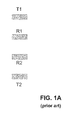
- FIG. 1A illustrates an electrical imager configuration according to the prior art.
- the imager consists of an array of two transmitters and two receivers sharing a similar size and being oriented in a one dimensional array. These transmitters and receivers are used to transmit high-frequency electrical signals into a formation and receive the reflection of the transmitted signals for imaging.
- FIGS. 2A and 2B when imaging the phase and attenuation of a formation downhole using the imager as discussed above, the imager fails to accurately represent the resolution of formation fractures in both the horizontal and vertical directions.
- FIG. 2A illustrates an image of the attenuation of vertical and horizontal fractures downhole having equal widths
- FIG. 2B illustrates an image of the phase difference of the vertical and horizontal fractures in the formation.
- FIG. 2B an image of the phase difference of the formation is shown.
- the horizontal fracture is shown to be substantially darker than the vertical fracture.
- the contrast of the vertical fracture and the horizontal fracture should be the same. In true omni-directional imaging, contrasts representing fractures in a formation are accurately represented.
- current imagers lack the ability to provide a quantitative analysis of the resistivity and dielectric constant of a formation downhole.
- geologists and petrophysicists can more accurately evaluate formation parameters such as permeable layers, water and/or oil reservoirs, fractures, strike angles and/or dipping angles, etc.
- Current imaging tools are mostly limited to imaging and cannot provide both high resolution imaging and a quantitative analysis of formation resistivity and dielectric constant.
- the subject matter of the present disclosure is directed to overcoming, or at least reducing the effects of, one or more of the problems set forth above.
- the present disclosure provides a method and apparatus for generating an image of a downhole formation by firing a signal in the direction of a downhole formation using at least one transmitter in a horizontal array, firing a signal in the direction of the formation using at least one transmitter in a vertical array, where the fired signals engage the downhole formation, receiving signals associated with the fired signals after the fired signals have engaged the formation, and using the received signals to determine one or more vertical and horizontal formation parameters for generating an omni-directional image using the formation parameters.
- inventions provide a method and apparatus for using at least one transmitter in either a vertical or horizontal array to fire signals in the direction of a downhole formation, where the fired signals engage the downhole formation, and receiving signals associated with the fired signals after the fired signals have engaged the downhole formation, wherein the received signals represent quantitative formation data and are used to determine one or more vertical or horizontal quantitative formation parameters.
- FIG. 1A illustrates an electrical imager configuration according to the prior art.
- FIG. 2A illustrates an image of the attenuation of vertical and horizontal fractures in a formation using an electrical imager having two transmitters and two receivers downhole according to the prior art.
- FIG. 2B illustrates an image of the phase difference of vertical and horizontal fractures in a formation downhole using an electrical imager having two transmitters and two receivers according to the prior art.
- FIG. 3A illustrates an electrical imager configuration having widened transmitter apertures according to the present disclosure.
- FIG. 3B illustrates an electrical imager configuration having widened transmitter apertures and compact receivers according to the present disclosure.
- FIG. 4A illustrates an open ended waveguide antenna element according to the present disclosure.
- FIG. 4B illustrates antenna elements disposed in a downhole tool.
- FIG. 5 illustrates an electrical imager configuration according to the present disclosure.
- FIG. 6 illustrates an image of the attenuation of vertical and horizontal fractures in a formation downhole using an electrical imager having four transmitters and four receivers according to the present disclosure.
- FIG. 7 illustrates an image of the phase difference of vertical and horizontal fractures in a formation downhole using an electrical imager having four transmitters and four receivers according to the present disclosure.
- FIG. 8A illustrates an alternative configuration of an electrical imager configuration having curved transmitters and receivers.
- FIG. 8B illustrates an alternative configuration of an electrical imager configuration having curved transmitters.
- FIG. 9 illustrates an alternative configuration of an electrical imager configuration.
- current imager designs are typically composed of a single array, having no significant size difference or orientation with respect to transmitters and receivers. By enlarging the aperture of the transmitter and by having a compact orientation of the receivers, the resolution of the imager may be increased.
- the electrical imager has a plurality of transmitters (T 1 and T 2 ) and receivers (R 1 and R 2 ) for transmitting high frequency (e.g., hundreds of megahertz to up to one or more gigahertz) electrical signals into a formation downhole and receiving the transmitted signals.
- the received signals are subsequently processed downhole or at the surface using a surface processor (not shown) in order to process quantitative data of the formation (e.g., resistivity and/or dielectric constant) and/or provide representative images of formation properties downhole.
- the electrical imager may work in water based or oil based mud.
- FIG. 3A further illustrates an electrical imager configuration having widened transmitter apertures according to the present disclosure.
- the openings or apertures of the transmitters T 1 and T 2 have an increased size.
- the transmitters can transmit stronger signals for engaging the subsurface wall while also reducing the reflection of the transmitted signal. This is because, as the cross-section of the transmitter apertures (e.g., waveguide antennas T 1 and T 2 gets larger, the permittivity of the material filled inside the transmitters will be lower. This will result in a smaller permittivity contrast between the material inside of the transmitter and the oil based mud outside of the transmitter. As a result, any unwanted wave reflection will be minimized-which will result in more signal/energy engaging (i.e., transmitted into) the mud and the formation.
- FIG. 3B the electrical imager configuration of FIG. 3A having widened transmitter apertures is shown while also incorporating a more compact receiver array.
- receivers R 1 and R 2
- the electrical imager will produce a higher-resolution image.
- this disclosure is not limited to a particular type of antenna used for transmitting and/or receiving, any antenna having widened apertures may be used.
- open-ended waveguide antenna element 400 having a widened aperture is shown.
- open-ended waveguide antenna elements 400 may include a waveguide 415 that terminates with a widened opening or hollow center 410 .
- antenna elements 400 may either be transmitters or receivers, transmitters having widened apertures 410 will allow the imager to produce stronger signals and reduce signal reflection. Referring to the open-ended waveguide antenna 400 shown in FIG.
- the antenna element 400 may further have a coax feeder 420 that connects to the waveguide 415 and feeds a coax inner conductor 425 into the waveguide 415 from the coax feeder 420 . This will effectively allow communication with the waveguide antennas while the antennas are disposed downhole.
- multiple antenna elements 400 are shown disposed in a downhole tool 430 .
- the downhole tool 430 is shown having three antennas 400 disposed therein, in an array along the major axis of the tool.
- the antenna elements 400 are shown disposed along the top side of the downhole tool 430 , the antenna elements 400 may be disposed on any side of the downhole tool 430 .
- the openings ( 410 ) of the antenna elements 400 are filled with an epoxy or other non-conducting filler.
- the epoxy serves to protect the antenna elements 400 during logging while drilling operations.
- the shape of the horn antenna elements are not limited to having a rectangular aperture, as different designs may be incorporated.
- FIG. 5 illustrates an electrical imager 500 configuration according to the present disclosure.
- the imager 500 has an antenna configuration consisting of antenna arrays in the vertical direction (i.e., T 1 , T 2 , R 1 and R 2 ) and the horizontal direction (i.e., T 3 , T 4 , R 3 and R 4 ).
- T 1 , T 2 , R 1 and R 2 the vertical direction
- T 3 , T 4 , R 3 and R 4 the horizontal direction
- having a dual-directional transmitter/receiver antenna configuration will allow the imager 500 to take dual compensation measurements of the formation and use the measurements to create an omni-directional image of fractures within the formation.
- the voltage compensation (Vcomp) for transmitters T 1 -T 4 and receivers R 1 -R 4 can be used to determine the attenuation and phase difference of the formation.
- the attenuation and phase difference can subsequently be used for producing high resolution images in both the vertical and horizontal planes of reference.
- the receivers R 1 -R 4 are positioned close to one another for increased imaging resolution.
- the receivers R 1 -R 4 may be separated between 6 cm to within 3 cm of each other for increased resolution.
- the displacement of the receivers with respect to one another may however be outside of this range.
- Transmitters T 1 -T 4 are also shown around (i.e., surrounding) the compact receiver group R 1 -R 4 and can be used to transmit signals into the formation downhole, and the signals received by receivers R 1 -R 4 may be used for creating a omnidirectional picture of the phase and attenuation of the formation downhole.
- FIG. 7 illustrates an image of the phase difference of the vertical V and horizontal H fractures in the formation using the electrical imager 500 having four transmitters and four receivers according to the present disclosure.
- the representative image shows the vertical and horizontal lines having similar contrast or intensity. This information accurately indicates that the representative formation has fractures of equal widths in both the horizontal H and vertical V planes.
- the imager 500 can present omni-directional information, the information will be more accurate than information received from imagers having only two transmitters and two receivers. This is because the information more accurately represents attenuation and phase difference of formation fractures in each plane of reference.
- transmitters T 1 -T 4 and receivers R 1 -R 4 all have a curved shape to their design.
- the curved design will enhance imager placement uniformity with the LWD tool.
- the curved design will also enable more of the transmitted signal to be directed to target area, thereby enhancing measurement.
- FIG. 8B likewise illustrates transmitters T 1 -T 4 having curved apertures.
- receivers R 1 -R 4 are oriented in a compact surface area, having a curved receiver apertures may not necessarily enhance measurement resolution, and therefore may not be desired.
- the electrical imager 500 presently disclosed may also provide high resolution quantitative bedding analysis of formation resistivity and dielectric constant.
- the design shown in FIG. 5 having transmitters (T 1 T 2 T 3 T 4 ) and receivers (R 1 R 2 R 3 R 4 ) may only be designed for qualitatively resolving features on the formation wall (i.e. generating formation wall images), and may not be designed for quantitative formation analysis (i.e. the inversion of formation resistivity and dielectric constant).
- the imager may be designed differently so that it is very sensitive to local/shallow variations on the formation wall. In this aspect, the imager's receivers may be designed to be close to each other.
- the imager may be designed to have a much larger spacing between receivers, and consequently much deeper DOI. Measurements using this design may be less sensitive to local/shallow variations of the formation wall, and may be more suitable for quantitative analyses of the formation parameters such as resistivity and dielectric constant.
- an alternative configuration of an electrical imager 500 being capable of providing a quantitative analysis of a formation is shown.
- the imager 500 design includes two additional transmitters T 5 and T 6 , and when the design is oriented for quantitatively analyzing the resistivity and dielectric constant, transmitters T 1 and T 2 (as previously discussed) can be interchanged for receivers R 5 and R 6 .
- the received signals may be subsequently processed downhole or at the surface using a surface processor (not shown) in order to process quantitative data of the formation (e.g., resistivity and/or dielectric constant).
- a surface processor not shown
- transmitters T 1 and T 2 may be again used with receivers R 1 and R 2 for providing representative images of formation properties downhole.
- the Vcomp determined from transmitters T 5 and T 6 and receivers R 5 and R 6 can be used to determine the attenuation and phase difference of the formation.
- any of the illustrated antenna elements disclosed may have different orientations or designs, and are not limited to the illustrations herein.
Landscapes
- Life Sciences & Earth Sciences (AREA)
- Physics & Mathematics (AREA)
- Engineering & Computer Science (AREA)
- Geology (AREA)
- Mining & Mineral Resources (AREA)
- General Life Sciences & Earth Sciences (AREA)
- Environmental & Geological Engineering (AREA)
- Geophysics (AREA)
- Fluid Mechanics (AREA)
- Geochemistry & Mineralogy (AREA)
- Remote Sensing (AREA)
- General Physics & Mathematics (AREA)
- Electromagnetism (AREA)
- Geophysics And Detection Of Objects (AREA)
- Earth Drilling (AREA)
- Excavating Of Shafts Or Tunnels (AREA)
Abstract
Description
Claims (32)
Priority Applications (4)
| Application Number | Priority Date | Filing Date | Title |
|---|---|---|---|
| US14/305,227 US9797236B2 (en) | 2014-06-16 | 2014-06-16 | Logging while drilling electrical imager and method for measurement in oil based mud |
| NO20150776A NO20150776A1 (en) | 2014-06-16 | 2015-06-15 | Logging While Drilling Electrical Imager and Method for Measurement in Oil Based Mud |
| CA2894322A CA2894322C (en) | 2014-06-16 | 2015-06-15 | Logging while drilling electrical imager and method for measurement in oil based mud |
| GB1510581.0A GB2534618B (en) | 2014-06-16 | 2015-06-16 | Logging while drilling electrical imager and method for measurement in oil based mud |
Applications Claiming Priority (1)
| Application Number | Priority Date | Filing Date | Title |
|---|---|---|---|
| US14/305,227 US9797236B2 (en) | 2014-06-16 | 2014-06-16 | Logging while drilling electrical imager and method for measurement in oil based mud |
Publications (2)
| Publication Number | Publication Date |
|---|---|
| US20150361780A1 US20150361780A1 (en) | 2015-12-17 |
| US9797236B2 true US9797236B2 (en) | 2017-10-24 |
Family
ID=53784830
Family Applications (1)
| Application Number | Title | Priority Date | Filing Date |
|---|---|---|---|
| US14/305,227 Expired - Fee Related US9797236B2 (en) | 2014-06-16 | 2014-06-16 | Logging while drilling electrical imager and method for measurement in oil based mud |
Country Status (4)
| Country | Link |
|---|---|
| US (1) | US9797236B2 (en) |
| CA (1) | CA2894322C (en) |
| GB (1) | GB2534618B (en) |
| NO (1) | NO20150776A1 (en) |
Families Citing this family (2)
| Publication number | Priority date | Publication date | Assignee | Title |
|---|---|---|---|---|
| CN115012925B (en) * | 2022-08-08 | 2022-10-21 | 西南石油大学 | Experimental determination method for vertical gas well shaft flow pattern under high pressure condition |
| CN117688719A (en) * | 2023-10-30 | 2024-03-12 | 中海石油(中国)有限公司 | A method for calculating the fracture width of FMI electrical imaging logging based on model wells |
Citations (12)
| Publication number | Priority date | Publication date | Assignee | Title |
|---|---|---|---|---|
| US4525715A (en) * | 1981-11-25 | 1985-06-25 | Tele-Drill, Inc. | Toroidal coupled telemetry apparatus |
| US6580268B2 (en) * | 2001-08-28 | 2003-06-17 | Weatherford/Lamb, Inc. | Sucker rod dimension measurement and flaw detection system |
| US6765385B2 (en) * | 2001-11-13 | 2004-07-20 | Weatherford/Lamb, Inc. | Method, apparatus and system for compensating the effects of borehole variations |
| GB2400670A (en) | 2001-03-01 | 2004-10-20 | Baker Hughes Inc | An efficient and accurate Pseudo 2-D inversion scheme for multicomponent induction log data |
| GB2407641A (en) | 2003-10-27 | 2005-05-04 | Schlumberger Holdings | Apparatus and methods for determining isotropic and anisotropic formation resistivity in the presence of invasion |
| WO2005078481A1 (en) | 2004-02-04 | 2005-08-25 | Baker Hughes Incorporated | Method of eliminating conductive drill parasitic influence on the measurements of transient electromagnetic components in mwd tools |
| CA2651097A1 (en) | 2006-05-03 | 2007-11-15 | Baker Hughes Incorporated | Method and apparatus for tensorial micro-resistivity imaging in oil-based muds |
| US7755361B2 (en) * | 2004-07-14 | 2010-07-13 | Schlumberger Technology Corporation | Apparatus and system for well placement and reservoir characterization |
| US8049508B2 (en) * | 2007-03-16 | 2011-11-01 | Baker Hughes Incorporated | Method and apparatus for determining formation boundary near the bit for conductive mud |
| WO2012037340A1 (en) | 2010-09-15 | 2012-03-22 | Schlumberger Canada Limited | Real-time fracture detection and fracture orientation estimation |
| CN203161203U (en) | 2012-07-20 | 2013-08-28 | 中国石油集团长城钻探工程有限公司 | Triaxial quadrature coil system |
| US20140306711A1 (en) * | 2013-04-15 | 2014-10-16 | Weatherford/Lamb, Inc. | Method and Apparatus for Detection and Quantification of Borehole Standoff |
-
2014
- 2014-06-16 US US14/305,227 patent/US9797236B2/en not_active Expired - Fee Related
-
2015
- 2015-06-15 CA CA2894322A patent/CA2894322C/en not_active Expired - Fee Related
- 2015-06-15 NO NO20150776A patent/NO20150776A1/en not_active Application Discontinuation
- 2015-06-16 GB GB1510581.0A patent/GB2534618B/en not_active Expired - Fee Related
Patent Citations (12)
| Publication number | Priority date | Publication date | Assignee | Title |
|---|---|---|---|---|
| US4525715A (en) * | 1981-11-25 | 1985-06-25 | Tele-Drill, Inc. | Toroidal coupled telemetry apparatus |
| GB2400670A (en) | 2001-03-01 | 2004-10-20 | Baker Hughes Inc | An efficient and accurate Pseudo 2-D inversion scheme for multicomponent induction log data |
| US6580268B2 (en) * | 2001-08-28 | 2003-06-17 | Weatherford/Lamb, Inc. | Sucker rod dimension measurement and flaw detection system |
| US6765385B2 (en) * | 2001-11-13 | 2004-07-20 | Weatherford/Lamb, Inc. | Method, apparatus and system for compensating the effects of borehole variations |
| GB2407641A (en) | 2003-10-27 | 2005-05-04 | Schlumberger Holdings | Apparatus and methods for determining isotropic and anisotropic formation resistivity in the presence of invasion |
| WO2005078481A1 (en) | 2004-02-04 | 2005-08-25 | Baker Hughes Incorporated | Method of eliminating conductive drill parasitic influence on the measurements of transient electromagnetic components in mwd tools |
| US7755361B2 (en) * | 2004-07-14 | 2010-07-13 | Schlumberger Technology Corporation | Apparatus and system for well placement and reservoir characterization |
| CA2651097A1 (en) | 2006-05-03 | 2007-11-15 | Baker Hughes Incorporated | Method and apparatus for tensorial micro-resistivity imaging in oil-based muds |
| US8049508B2 (en) * | 2007-03-16 | 2011-11-01 | Baker Hughes Incorporated | Method and apparatus for determining formation boundary near the bit for conductive mud |
| WO2012037340A1 (en) | 2010-09-15 | 2012-03-22 | Schlumberger Canada Limited | Real-time fracture detection and fracture orientation estimation |
| CN203161203U (en) | 2012-07-20 | 2013-08-28 | 中国石油集团长城钻探工程有限公司 | Triaxial quadrature coil system |
| US20140306711A1 (en) * | 2013-04-15 | 2014-10-16 | Weatherford/Lamb, Inc. | Method and Apparatus for Detection and Quantification of Borehole Standoff |
Non-Patent Citations (2)
| Title |
|---|
| Combined Search and Examination Report in counterpart UK App. GB1510581.0, dated Nov. 24, 2015. |
| First Office Action in counterpart Canadian App. 2,894,322, dated Jun. 1, 2016, 3-pgs. |
Also Published As
| Publication number | Publication date |
|---|---|
| NO20150776A1 (en) | 2015-12-17 |
| US20150361780A1 (en) | 2015-12-17 |
| GB2534618A (en) | 2016-08-03 |
| CA2894322C (en) | 2019-05-07 |
| GB2534618B (en) | 2017-07-19 |
| GB201510581D0 (en) | 2015-07-29 |
| CA2894322A1 (en) | 2015-12-16 |
Similar Documents
| Publication | Publication Date | Title |
|---|---|---|
| RU2496127C2 (en) | Electromagnetic logging apparatus | |
| US6191586B1 (en) | Method and apparatus for azimuthal electromagnetic well logging using shielded antennas | |
| US9903199B2 (en) | Use of metamaterial to enhance measurement of dielectric properties | |
| CA2497888C (en) | Method and apparatus for directional resistivity measurement while drilling | |
| US20140253131A1 (en) | Apparatus and Method for Directional Resistivity Measurement While Drilling Using Slot Antenna | |
| CN101889217B (en) | Method and apparatus for electromagnetic logging of formations | |
| WO2011115646A1 (en) | Single well reservoir imaging apparatus and methods | |
| CN104903749B (en) | Deep bearing system with multipole sensors | |
| US20180011212A1 (en) | System for exploring underground geophysical properties and method for analyzing underground geophysical properties using the same | |
| Sato et al. | Polarimetric borehole radar system for fracture measurement | |
| Tellez et al. | Ground‐penetrating radar for close‐in mine detection | |
| US9797236B2 (en) | Logging while drilling electrical imager and method for measurement in oil based mud | |
| Sato et al. | Cross-polarization borehole radar measurements with a slot antenna | |
| KR101437777B1 (en) | A monopole antenna structured magnetic resonance imaging device | |
| Wada et al. | Fractures and rock properties estimated by 3D directional borehole radar | |
| Wang et al. | Investigation of forward-looking synthetic circular array for subsurface imaging in tunnel boring machine application | |
| Lee et al. | Ring‐shaped antenna array for multistatic microwave breast imaging systems | |
| EP0816872A1 (en) | Borehole probe with one or more radar antennae | |
| Guy et al. | Recognition of borehole radar cable-related effects using variable offset sounding | |
| De et al. | Ultrabroadband Electromagnetic Well Logging: A Potential Future Technology | |
| Sugak et al. | Large current radiator for long range GPR applications | |
| Wright et al. | Imaging and modeling new VETEM data | |
| Sato et al. | Polarimetric borehole radar approach to fracture classification | |
| Takahashi et al. | Interferometric borehole radar system | |
| Mostapha et al. | Study Effect of Objects Orientation in the Mediums On GPR Signal Reflections Using FDTD Simulation |
Legal Events
| Date | Code | Title | Description |
|---|---|---|---|
| AS | Assignment |
Owner name: WEATHERFORD/LAMB, INC., TEXAS Free format text: ASSIGNMENT OF ASSIGNORS INTEREST;ASSIGNOR:CHEN, JIEFU;REEL/FRAME:033108/0431 Effective date: 20140616 |
|
| AS | Assignment |
Owner name: WEATHERFORD TECHNOLOGY HOLDINGS, LLC., TEXAS Free format text: ASSIGNMENT OF ASSIGNORS INTEREST;ASSIGNOR:WEATHERFORD/LAMB, INC,;REEL/FRAME:037141/0593 Effective date: 20151119 |
|
| STCF | Information on status: patent grant |
Free format text: PATENTED CASE |
|
| AS | Assignment |
Owner name: WELLS FARGO BANK NATIONAL ASSOCIATION AS AGENT, TEXAS Free format text: SECURITY INTEREST;ASSIGNORS:WEATHERFORD TECHNOLOGY HOLDINGS LLC;WEATHERFORD NETHERLANDS B.V.;WEATHERFORD NORGE AS;AND OTHERS;REEL/FRAME:051891/0089 Effective date: 20191213 |
|
| AS | Assignment |
Owner name: DEUTSCHE BANK TRUST COMPANY AMERICAS, AS ADMINISTR Free format text: SECURITY INTEREST;ASSIGNORS:WEATHERFORD TECHNOLOGY HOLDINGS, LLC;WEATHERFORD NETHERLANDS B.V.;WEATHERFORD NORGE AS;AND OTHERS;REEL/FRAME:051419/0140 Effective date: 20191213 Owner name: DEUTSCHE BANK TRUST COMPANY AMERICAS, AS ADMINISTRATIVE AGENT, NEW YORK Free format text: SECURITY INTEREST;ASSIGNORS:WEATHERFORD TECHNOLOGY HOLDINGS, LLC;WEATHERFORD NETHERLANDS B.V.;WEATHERFORD NORGE AS;AND OTHERS;REEL/FRAME:051419/0140 Effective date: 20191213 |
|
| AS | Assignment |
Owner name: WEATHERFORD TECHNOLOGY HOLDINGS, LLC, TEXAS Free format text: RELEASE BY SECURED PARTY;ASSIGNOR:WELLS FARGO BANK, NATIONAL ASSOCIATION;REEL/FRAME:053838/0323 Effective date: 20200828 Owner name: WEATHERFORD SWITZERLAND TRADING AND DEVELOPMENT GMBH, TEXAS Free format text: RELEASE BY SECURED PARTY;ASSIGNOR:WELLS FARGO BANK, NATIONAL ASSOCIATION;REEL/FRAME:053838/0323 Effective date: 20200828 Owner name: WEATHERFORD NORGE AS, TEXAS Free format text: RELEASE BY SECURED PARTY;ASSIGNOR:WELLS FARGO BANK, NATIONAL ASSOCIATION;REEL/FRAME:053838/0323 Effective date: 20200828 Owner name: WEATHERFORD NETHERLANDS B.V., TEXAS Free format text: RELEASE BY SECURED PARTY;ASSIGNOR:WELLS FARGO BANK, NATIONAL ASSOCIATION;REEL/FRAME:053838/0323 Effective date: 20200828 Owner name: PRECISION ENERGY SERVICES ULC, TEXAS Free format text: RELEASE BY SECURED PARTY;ASSIGNOR:WELLS FARGO BANK, NATIONAL ASSOCIATION;REEL/FRAME:053838/0323 Effective date: 20200828 Owner name: WEATHERFORD CANADA LTD., TEXAS Free format text: RELEASE BY SECURED PARTY;ASSIGNOR:WELLS FARGO BANK, NATIONAL ASSOCIATION;REEL/FRAME:053838/0323 Effective date: 20200828 Owner name: PRECISION ENERGY SERVICES, INC., TEXAS Free format text: RELEASE BY SECURED PARTY;ASSIGNOR:WELLS FARGO BANK, NATIONAL ASSOCIATION;REEL/FRAME:053838/0323 Effective date: 20200828 Owner name: WEATHERFORD U.K. LIMITED, TEXAS Free format text: RELEASE BY SECURED PARTY;ASSIGNOR:WELLS FARGO BANK, NATIONAL ASSOCIATION;REEL/FRAME:053838/0323 Effective date: 20200828 Owner name: HIGH PRESSURE INTEGRITY, INC., TEXAS Free format text: RELEASE BY SECURED PARTY;ASSIGNOR:WELLS FARGO BANK, NATIONAL ASSOCIATION;REEL/FRAME:053838/0323 Effective date: 20200828 Owner name: WILMINGTON TRUST, NATIONAL ASSOCIATION, MINNESOTA Free format text: SECURITY INTEREST;ASSIGNORS:WEATHERFORD TECHNOLOGY HOLDINGS, LLC;WEATHERFORD NETHERLANDS B.V.;WEATHERFORD NORGE AS;AND OTHERS;REEL/FRAME:054288/0302 Effective date: 20200828 |
|
| MAFP | Maintenance fee payment |
Free format text: PAYMENT OF MAINTENANCE FEE, 4TH YEAR, LARGE ENTITY (ORIGINAL EVENT CODE: M1551); ENTITY STATUS OF PATENT OWNER: LARGE ENTITY Year of fee payment: 4 |
|
| AS | Assignment |
Owner name: WILMINGTON TRUST, NATIONAL ASSOCIATION, MINNESOTA Free format text: SECURITY INTEREST;ASSIGNORS:WEATHERFORD TECHNOLOGY HOLDINGS, LLC;WEATHERFORD NETHERLANDS B.V.;WEATHERFORD NORGE AS;AND OTHERS;REEL/FRAME:057683/0706 Effective date: 20210930 Owner name: WEATHERFORD U.K. LIMITED, TEXAS Free format text: RELEASE BY SECURED PARTY;ASSIGNOR:WILMINGTON TRUST, NATIONAL ASSOCIATION;REEL/FRAME:057683/0423 Effective date: 20210930 Owner name: PRECISION ENERGY SERVICES ULC, TEXAS Free format text: RELEASE BY SECURED PARTY;ASSIGNOR:WILMINGTON TRUST, NATIONAL ASSOCIATION;REEL/FRAME:057683/0423 Effective date: 20210930 Owner name: WEATHERFORD SWITZERLAND TRADING AND DEVELOPMENT GMBH, TEXAS Free format text: RELEASE BY SECURED PARTY;ASSIGNOR:WILMINGTON TRUST, NATIONAL ASSOCIATION;REEL/FRAME:057683/0423 Effective date: 20210930 Owner name: WEATHERFORD CANADA LTD, TEXAS Free format text: RELEASE BY SECURED PARTY;ASSIGNOR:WILMINGTON TRUST, NATIONAL ASSOCIATION;REEL/FRAME:057683/0423 Effective date: 20210930 Owner name: PRECISION ENERGY SERVICES, INC., TEXAS Free format text: RELEASE BY SECURED PARTY;ASSIGNOR:WILMINGTON TRUST, NATIONAL ASSOCIATION;REEL/FRAME:057683/0423 Effective date: 20210930 Owner name: HIGH PRESSURE INTEGRITY, INC., TEXAS Free format text: RELEASE BY SECURED PARTY;ASSIGNOR:WILMINGTON TRUST, NATIONAL ASSOCIATION;REEL/FRAME:057683/0423 Effective date: 20210930 Owner name: WEATHERFORD NORGE AS, TEXAS Free format text: RELEASE BY SECURED PARTY;ASSIGNOR:WILMINGTON TRUST, NATIONAL ASSOCIATION;REEL/FRAME:057683/0423 Effective date: 20210930 Owner name: WEATHERFORD NETHERLANDS B.V., TEXAS Free format text: RELEASE BY SECURED PARTY;ASSIGNOR:WILMINGTON TRUST, NATIONAL ASSOCIATION;REEL/FRAME:057683/0423 Effective date: 20210930 Owner name: WEATHERFORD TECHNOLOGY HOLDINGS, LLC, TEXAS Free format text: RELEASE BY SECURED PARTY;ASSIGNOR:WILMINGTON TRUST, NATIONAL ASSOCIATION;REEL/FRAME:057683/0423 Effective date: 20210930 Owner name: WEATHERFORD TECHNOLOGY HOLDINGS, LLC, TEXAS Free format text: RELEASE OF SECURITY INTEREST;ASSIGNOR:WILMINGTON TRUST, NATIONAL ASSOCIATION;REEL/FRAME:057683/0423 Effective date: 20210930 Owner name: WEATHERFORD NETHERLANDS B.V., TEXAS Free format text: RELEASE OF SECURITY INTEREST;ASSIGNOR:WILMINGTON TRUST, NATIONAL ASSOCIATION;REEL/FRAME:057683/0423 Effective date: 20210930 Owner name: WEATHERFORD NORGE AS, TEXAS Free format text: RELEASE OF SECURITY INTEREST;ASSIGNOR:WILMINGTON TRUST, NATIONAL ASSOCIATION;REEL/FRAME:057683/0423 Effective date: 20210930 Owner name: HIGH PRESSURE INTEGRITY, INC., TEXAS Free format text: RELEASE OF SECURITY INTEREST;ASSIGNOR:WILMINGTON TRUST, NATIONAL ASSOCIATION;REEL/FRAME:057683/0423 Effective date: 20210930 Owner name: PRECISION ENERGY SERVICES, INC., TEXAS Free format text: RELEASE OF SECURITY INTEREST;ASSIGNOR:WILMINGTON TRUST, NATIONAL ASSOCIATION;REEL/FRAME:057683/0423 Effective date: 20210930 Owner name: WEATHERFORD CANADA LTD, TEXAS Free format text: RELEASE OF SECURITY INTEREST;ASSIGNOR:WILMINGTON TRUST, NATIONAL ASSOCIATION;REEL/FRAME:057683/0423 Effective date: 20210930 Owner name: WEATHERFORD SWITZERLAND TRADING AND DEVELOPMENT GMBH, TEXAS Free format text: RELEASE OF SECURITY INTEREST;ASSIGNOR:WILMINGTON TRUST, NATIONAL ASSOCIATION;REEL/FRAME:057683/0423 Effective date: 20210930 Owner name: PRECISION ENERGY SERVICES ULC, TEXAS Free format text: RELEASE OF SECURITY INTEREST;ASSIGNOR:WILMINGTON TRUST, NATIONAL ASSOCIATION;REEL/FRAME:057683/0423 Effective date: 20210930 Owner name: WEATHERFORD U.K. LIMITED, TEXAS Free format text: RELEASE OF SECURITY INTEREST;ASSIGNOR:WILMINGTON TRUST, NATIONAL ASSOCIATION;REEL/FRAME:057683/0423 Effective date: 20210930 |
|
| AS | Assignment |
Owner name: WELLS FARGO BANK, NATIONAL ASSOCIATION, NORTH CAROLINA Free format text: PATENT SECURITY INTEREST ASSIGNMENT AGREEMENT;ASSIGNOR:DEUTSCHE BANK TRUST COMPANY AMERICAS;REEL/FRAME:063470/0629 Effective date: 20230131 |
|
| FEPP | Fee payment procedure |
Free format text: MAINTENANCE FEE REMINDER MAILED (ORIGINAL EVENT CODE: REM.); ENTITY STATUS OF PATENT OWNER: LARGE ENTITY |
|
| LAPS | Lapse for failure to pay maintenance fees |
Free format text: PATENT EXPIRED FOR FAILURE TO PAY MAINTENANCE FEES (ORIGINAL EVENT CODE: EXP.); ENTITY STATUS OF PATENT OWNER: LARGE ENTITY |
|
| STCH | Information on status: patent discontinuation |
Free format text: PATENT EXPIRED DUE TO NONPAYMENT OF MAINTENANCE FEES UNDER 37 CFR 1.362 |
|
| FP | Lapsed due to failure to pay maintenance fee |
Effective date: 20251024 |