US9796466B2 - Variable coupler drive - Google Patents
Variable coupler drive Download PDFInfo
- Publication number
- US9796466B2 US9796466B2 US14/770,433 US201314770433A US9796466B2 US 9796466 B2 US9796466 B2 US 9796466B2 US 201314770433 A US201314770433 A US 201314770433A US 9796466 B2 US9796466 B2 US 9796466B2
- Authority
- US
- United States
- Prior art keywords
- drive
- rotational
- spinner
- drive table
- coupled
- Prior art date
- Legal status (The legal status is an assumption and is not a legal conclusion. Google has not performed a legal analysis and makes no representation as to the accuracy of the status listed.)
- Expired - Fee Related, expires
Links
Images


Classifications
-
- B—PERFORMING OPERATIONS; TRANSPORTING
- B63—SHIPS OR OTHER WATERBORNE VESSELS; RELATED EQUIPMENT
- B63H—MARINE PROPULSION OR STEERING
- B63H23/00—Transmitting power from propulsion power plant to propulsive elements
- B63H23/02—Transmitting power from propulsion power plant to propulsive elements with mechanical gearing
- B63H23/06—Transmitting power from propulsion power plant to propulsive elements with mechanical gearing for transmitting drive from a single propulsion power unit
-
- B—PERFORMING OPERATIONS; TRANSPORTING
- B63—SHIPS OR OTHER WATERBORNE VESSELS; RELATED EQUIPMENT
- B63H—MARINE PROPULSION OR STEERING
- B63H23/00—Transmitting power from propulsion power plant to propulsive elements
- B63H23/02—Transmitting power from propulsion power plant to propulsive elements with mechanical gearing
-
- B—PERFORMING OPERATIONS; TRANSPORTING
- B63—SHIPS OR OTHER WATERBORNE VESSELS; RELATED EQUIPMENT
- B63H—MARINE PROPULSION OR STEERING
- B63H5/00—Arrangements on vessels of propulsion elements directly acting on water
- B63H5/07—Arrangements on vessels of propulsion elements directly acting on water of propellers
- B63H5/125—Arrangements on vessels of propulsion elements directly acting on water of propellers movably mounted with respect to hull, e.g. adjustable in direction, e.g. podded azimuthing thrusters
-
- F—MECHANICAL ENGINEERING; LIGHTING; HEATING; WEAPONS; BLASTING
- F16—ENGINEERING ELEMENTS AND UNITS; GENERAL MEASURES FOR PRODUCING AND MAINTAINING EFFECTIVE FUNCTIONING OF MACHINES OR INSTALLATIONS; THERMAL INSULATION IN GENERAL
- F16H—GEARING
- F16H15/00—Gearings for conveying rotary motion with variable gear ratio, or for reversing rotary motion, by friction between rotary members
- F16H15/02—Gearings for conveying rotary motion with variable gear ratio, or for reversing rotary motion, by friction between rotary members without members having orbital motion
- F16H15/04—Gearings providing a continuous range of gear ratios
- F16H15/06—Gearings providing a continuous range of gear ratios in which a member A of uniform effective diameter mounted on a shaft may co-operate with different parts of a member B
- F16H15/08—Gearings providing a continuous range of gear ratios in which a member A of uniform effective diameter mounted on a shaft may co-operate with different parts of a member B in which the member B is a disc with a flat or approximately flat friction surface
- F16H15/10—Gearings providing a continuous range of gear ratios in which a member A of uniform effective diameter mounted on a shaft may co-operate with different parts of a member B in which the member B is a disc with a flat or approximately flat friction surface in which the axes of the two members cross or intersect
-
- B—PERFORMING OPERATIONS; TRANSPORTING
- B63—SHIPS OR OTHER WATERBORNE VESSELS; RELATED EQUIPMENT
- B63H—MARINE PROPULSION OR STEERING
- B63H23/00—Transmitting power from propulsion power plant to propulsive elements
- B63H23/02—Transmitting power from propulsion power plant to propulsive elements with mechanical gearing
- B63H2023/0258—Transmitting power from propulsion power plant to propulsive elements with mechanical gearing comprising gearings with variable gear ratio, other than reversing drives or trolling drives
Definitions
- inventive technology described herein generally relates to the field of power transmission, more particularly power transmission through a mechanical drive system. More specifically, in certain embodiments the inventive technology includes methods and apparatus for a variable coupler drive utilizing, in one embodiment a dynamic drive-ratio gearing system to transmit a drive input for application with a variety of output uses. In a preferred embodiment, such a variable coupler drive may be used to transmit a rotational drive input to a drive shaft to power, for example, a variety of commercial and industrial applications.
- the inventive technology may be particularly suited for propeller propulsion based systems, such as ships, for example through an external propeller drive responsive to one or a plurality of variable coupler drive(s) devices.
- an external propeller drive may further be independently rotatable in 360° degrees while continuously receiving power from a variable coupler drive.
- Such rotational capabilities under powered conditions may allow a ship to execute a plurality of propeller power movements, such as lateral and/or angled propulsion as well as rotational movement along a central, and/or terminal axis.
- the inventive technology may also have applications for power generation through, for example, the capture of various types of power inputs, which can be transmitted through a dynamic drive-ratio gearing system allowing dynamic control of a generator output.
- the inventive technology disclosed herein may include apparatus and methods for a variable coupler drive that may achieve dynamic coupler-level regulation to generate the power output. Additional embodiments may include apparatus and methods for a variable couple drive lift to couple and de-couple the aforementioned variable coupler drive, perhaps through action of an actuator. In additional embodiments, the inventive technology may include apparatus and methods for an external propeller drive which may be powered by a variable coupler drive. In this embodiment, such a system may allow lateral and/or angled ship movements, as well as rotational propulsion along a central and/or proximal axis.
- a single or plurality of variable coupler drive(s) may power, again, a single or plurality of rotational external propeller drive(s) allowing not only coupler-level torque control over the rotational output—and eventual propeller rotation, but variable direction propulsion.
- Such an embodiment may also be adapted, and/or retrofitted to existing fixed-propeller ships.
- the inventive technology includes a variable coupler drive ( 1 a ) utilizing perhaps a rotating or rotatable cylinder ( 1 ), driven for example by a motor, which may generate a rotational drive input ( 2 ) at a desired speed.
- This rotating cylinder ( 1 ) may be dynamically coupled, for example in a slidable manner, with a spinner ( 5 ) element secured perhaps within an adaptable support bracket ( 6 ).
- Such adaptable support bracket ( 6 ) may be a non-rotational support joined with a spinner ( 5 ) through a rotational joint ( 4 ), such as a bearing joint allowing a spinner ( 5 ) to freely rotate within a bracket.
- This rotating spinner may be in contact, or brought into contact with a drive table ( 7 ) causing a controlled rotation.
- this drive table ( 7 ) may be supported by one or more rotational support system(s), such as a rotational support base ( 20 ) and may be further coupled to a rotatable drive shaft ( 8 ) which may be utilized to transmit the systems power output.
- this adaptable support bracket ( 6 ) may be joined with a variable position driver ( 10 ), through for example a variable position track ( 9 ) which may allow it—and the coupled spinner ( 5 )—to move across the circumference of the drive table.
- the position of the rotating spinner ( 5 ) may establish the system's drive ratio output based on the position of the spinner ( 5 ) in relation to the drive table's central axis.
- Such drive-ratio may be continuously and dynamically altered based on the position of the spinner in relation to the drive table's central axis.
- the inventive technology may achieve a desired drive-ratio without, perhaps, the need to neither alter the system's power input nor use traditional gearing “teeth” and/or a gear train, or other traditional step-wise gear mechanisms.
- inventive technology in some embodiments may allow for dynamic control of the drive system's output by adjusting the spinner's ( 5 ) position along the drive table ( 7 ).
- this dynamic control capability may allow the system's power output to not only remain constant, even during fluctuations of any power inputs, but also may allow for rapid increases and/or decreases in power output, perhaps in response to an external demand or load resistance by dynamically adjusting the spinner ( 5 ) to a new drive ratio position along the drive table ( 7 ).
- Another additional embodiment of such a variable coupler drive ( 1 a ) may allow for a rapid change in the direction of the drive's output without any traditional gearing or other switching mechanisms requiring the input to be turned off.
- variable coupler drive may adjust the spinner element from one side of the drive table to the opposite side or alternate variable drive ratio directional region ( 43 ), reversing the table's direction, and thus reversing the drive output as well without interruption of the systems drive input.
- Additional embodiments include method and apparatus to engage as well as disengage the drive table ( 7 ) from the spinner ( 5 ).
- a drive table lift may allow a centrally positioned drive table ( 7 ) to be raised and lowered to contact a rotating spinner ( 5 ).
- a drive input in this case a rotational drive input ( 2 ) provided by a motor may be dynamically coupled and/or de-coupled from the drive table further transmitting and/or stopping transmission of such input.
- Such a variable drive coupler switch may allow greater control of the system's output as well as a coupling and/or de-coupling switch modifying the systems power output.
- various positions along the drive table ( 7 ) may include spaced positions where the rotating spinner ( 5 ) may not be in contact with the drive table's surface generating, for example, a neutral “de-coupled” position.
- this variable drive coupler may be easily accessible for repairs or replacement.
- a centrally positioned translatable drive table support mount ( 25 ) may be detachable from the other supports through translatable interfaces ( 50 ) or connections and may slide, for example, on a slide bearing ( 29 ).
- This modular design may be adapted and allow for the quick removal and replacement of any of the various elements listed.
- a variable coupler drive may be used to power a fully-rotational propeller drive forming a rotational propeller drive system ( 1 b ).
- a rotational propeller drive system ( 1 b ) may include methods and apparatus for placement of a variable coupler drive ( 1 a ) perhaps internally along the hull of a ship to variably power a drive shaft ( 8 ) which may in turn be coupled to an external propeller drive ( 24 ), perhaps through a directional gear transmission ( 23 a ) and ( 23 b ).
- this external propeller drive may be part of a “pod” system placed at various points along the hull of a ship.
- this rotating drive shaft ( 8 ) may pass through a sealed rotational propeller drive housing ( 21 ) supported by a drive band rotational mount ( 18 ) and responsive to a propeller shaft ( 24 ).
- the drive housing ( 21 ) may be responsive to a rotational drive gear ( 16 ) coupled with perhaps a rotational drive band ( 17 ) so as to be independently rotatable, for example in 360° degrees while receiving and/or dynamically maintaining power from a variable coupler drive ( 1 a ).
- the present invention includes a variety of aspects, which may be combined in different ways.
- the following descriptions are provided to list elements and describe some of the embodiments of the present invention. These elements are listed with initial, and in some cases secondary or multiple embodiments, however it should be understood that they may be combined in any manner and in any number to create additional embodiments.
- the variously described examples and preferred embodiments should not be construed to limit the present invention to only the explicitly described systems, techniques, and applications. Further, this description should be understood to support and encompass descriptions and claims of all the various embodiments, systems, techniques, methods, devices, and applications with any number of the disclosed elements, with each element alone, and also with any and all various permutations and combinations of all elements in this or any subsequent application.
- Another objective of the current inventive technology may be to provide methods and apparatus for a variable coupler drive; a variable coupler drive switch; a variably coupled rotational propeller drive system; a rotational drive system; and a rotational propeller drive housing system, and various combinations thereof.
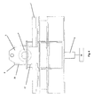
- FIG. 1 is a perspective view of a variable coupler drive in one embodiment thereof;
- FIG. 2 is a left side view of a variable coupler drive in one embodiment thereof;
- FIG. 3 is a front view of a variable coupler drive in one embodiment thereof;
- FIG. 4 is a right side view of a variable coupler drive in one embodiment thereof;
- FIG. 5 is a top view of a variable coupler drive in one embodiment thereof
- FIG. 6 is an alternative front view of a variable coupler drive in one embodiment thereof
- FIG. 7 is a bottom view of a variable coupler drive in one embodiment thereof
- FIG. 8 is a bottom perspective view of a variable coupler drive in one embodiment thereof;
- FIG. 9 is a translatable drive table support mount in one embodiment thereof.
- FIG. 10 is a drive base support in one embodiment thereof
- FIG. 11 is an alternative drive base support in one embodiment thereof.
- FIG. 12 is an individual variable position track mount in one embodiment thereof
- FIG. 13 is an individual upper bracket member in one embodiment thereof;
- FIG. 14 is a drive shaft having a drive shaft coupler interface in one embodiment thereof;
- FIG. 15 is an individual coupler support mount in one embodiment thereof;
- FIG. 16 is a drive shaft support coupler having a drive shaft coupler support interface in one embodiment thereof;
- FIG. 17 is a drive shaft support in one embodiment thereof
- FIG. 18 is a lower bracket member in one embodiment thereof.
- FIG. 19 is a drive table with a rotational interface surface in one embodiment thereof;
- FIG. 20 is an isolated rotational interface surface in one embodiment thereof
- FIG. 21 is a perspective view of a rotational propeller drive system with a drive shaft that may be coupled with, and/or responsive to, and/or continuous with a drive shaft from a variable coupler drive in one embodiment thereof;
- FIG. 22 is a side view of a rotational propeller drive system in one embodiment thereof;
- FIG. 23 is a back view of a rotational propeller drive system in one embodiment thereof;
- FIG. 24 is a perspective view of a rotational propeller drive system with an internal housing element removed in one embodiment thereof;
- FIG. 25 is a side view of a rotational propeller drive system with an internal housing element removed in one embodiment thereof;
- FIG. 26 is a top view of a rotational propeller drive system with an internal housing element removed in one embodiment thereof;
- FIG. 27 is a front view of a rotational propeller drive system with an internal housing element removed in one embodiment thereof;
- FIG. 28 is a perspective view of a rotational propeller drive system with an internal housing and rotational drive band elements removed to show a drive band rotational mount in one embodiment thereof;
- FIG. 29 is a perspective view of a rotational propeller drive system with various additional elements removed to view a rotary bearing in one embodiment thereof;
- FIG. 30 is a side view of a rotational propeller drive system with a rotational propeller drive housing removed in one embodiment thereof;
- FIG. 31 is an internal housing in one embodiment thereof
- FIG. 32 is a rotational propeller drive housing in one embodiment thereof;
- FIG. 33 is a rotational drive band in one embodiment thereof
- FIG. 34 is a directional drive shaft with a plurality of slide engagements in one embodiment thereof;
- FIG. 35 is a rotational drive gear in one embodiment thereof
- FIG. 36 is a rotational mount spacer in one embodiment thereof
- FIG. 37 is a top perspective view of a drive band rotational mount in one embodiment thereof;
- FIG. 38 is a bottom view of a drive band rotational mount in one embodiment thereof;
- FIG. 39 is a seal housing in one embodiment thereof.
- FIG. 40 is a directional gear transmission in one embodiment thereof
- FIG. 41 is an alternative directional gear transmission in one embodiment thereof.
- FIG. 42 is an external seal spacer in one embodiment thereof
- FIG. 43 is an external seal in one embodiment thereof.
- FIG. 44 is a diagrammatic representation of various ship movements that may be accomplished utilizing one or more of the claimed invention(s) in one embodiment thereof.
- the present invention includes a variety of aspects, which may be combined in different ways.
- the following descriptions are provided to list elements and describe some of the embodiments of the present invention. These elements are listed with initial embodiments, however it should be understood that they may be combined in any manner and in any number to create additional embodiments.
- the variously described examples and preferred embodiments should not be construed to limit the present invention to only the explicitly described systems, techniques, and applications. Further, this description should be understood to support and encompass descriptions and claims of all the various embodiments, systems, techniques, methods, devices, and applications with any number of the disclosed elements, with each element alone, and also with any and all various permutations and combinations of all elements in this or any subsequent application.
- responsive, and/or responsive to may indicate that two elements may be coupled in a manner so as to be directly or indirectly connected. In further embodiments, this may indicate that one element may respond with a discrete or non discrete action in response to the action or stimulus of a separate element.
- the inventive technology may include a variably coupled rotational propeller drive system having: at least one rotatable cylinder ( 1 ) that may be responsive to a rotational drive input ( 2 ) where a rotatable cylinder may be supported by at least one coupler support mount ( 3 ) through perhaps at least one rotational joint ( 4 ); at least one spinner ( 5 ) slidably coupled to a rotatable cylinder ( 1 ) so as to be rotationally responsive to the cylinder ( 1 ); at least one adaptable support bracket ( 6 ) coupled to a spinner ( 5 ) by, again perhaps at least one rotational joint ( 4 ); at least one drive table ( 7 ) mechanically coupled with at least one drive shaft ( 8 ) and perhaps rotationally responsive to a spinner ( 5 ); at least one variable position track ( 9 ) adjustably coupled to at least one variable position driver ( 10 ) and an adaptable
- certain embodiments of the current inventive technology may include methods and apparatus for a variable coupler drive ( 1 a ) generally comprising: at least one rotatable cylinder ( 1 ) responsive to a rotational drive input ( 2 ).
- a rotatable cylinder ( 1 ) may be supported by at least one coupler support mount ( 3 ) through, for example, a rotational joint ( 4 ) allowing it to freely rotate in response to, in this embodiment, the rotational drive input ( 2 ).
- a spinner ( 5 ) element may be slidably coupled to a rotatable cylinder ( 1 ).
- the spinner ( 5 ) may be slidably coupled with a rotatable cylinder ( 1 ) such that the spinner may rotate in response to a rotatable cylinder ( 1 ), while also being able to slide laterally along the length of the cylinder ( 1 ).
- This slidable coupling may be accomplished in some embodiments through the action of a non-rotational adaptable support bracket ( 6 ) coupled to a spinner ( 5 ) by, for example a rotational joint ( 4 ).
- certain embodiments of the inventive technology may include the steps of: slidably securing at least one spinner ( 5 ) to a rotatable cylinder ( 1 ) wherein the cylinder is supported by at least one coupler support mount ( 3 ) through at least one rotational joint ( 4 ); adaptably securing a spinner ( 5 ) to at least one adaptable support bracket ( 6 ) through at least one rotational joint ( 4 ); adjustably coupling a variable position track ( 9 ) to at least one variable position driver ( 10 ) and an adaptable support bracket ( 6 ); generating a rotational drive input ( 2 ); transferring the rotational drive input ( 2 ) causing rotation of a rotatable cylinder ( 1 ); rotating the spinner ( 5 ) slidably secured to a rotatable cylinder ( 1 ); rotating at least one drive table ( 7 ) rotationally responsive to the spinner ( 5 ); rotating at least one drive shaft ( 8 ) mechanically coupled with
- FIG. 1 may include a drive table ( 7 ) element that may further be mechanically coupled with at least one drive shaft ( 8 ).
- a mechanical coupling is not limiting as such a term may include any direct as well as indirect connection as well as any connection, again whether direct or indirect such that the two elements are responsive with, or on one another.
- this drive table ( 7 ) may be rotationally responsive to a spinner ( 5 ).
- the term “responsive,” or “responsive to” may encompass any direct and/or indirect coupling, connection or interaction of any two or more elements such that the element(s) may respond with a discrete or non-discrete action(s) in response to the action(s) or stimulus of any other separate element(s).
- the aforementioned drive table ( 7 ) may be placed into contact, or may be in existing contact with a spinner ( 5 ) such that, in one embodiment the rotational energy of a spinner ( 5 ) may be transmitted to the drive table ( 7 ) causing a controlled rotation.
- this rotating drive table ( 7 ) may be used to store and/or transmit, in this case, rotational energy generated from a rotational drive input ( 2 ).
- energy may be transferred to a drive table ( 7 ) through application of any torque force, for example through contact with a rotating spinner ( 5 ) element, thereby increasing its rotational speed, and hence its stored energy.
- This rotating drive table ( 7 ) may transmit and/or release this stored energy by subsequently applying torque to a mechanical load, thereby decreasing its rotational speed.
- this torque force may be transmitted through a drive shaft ( 8 ) to, for example, power a propeller drive shaft ( 24 ).
- the rotational energy stored in such a drive table may be applied to any mechanical load in order to accomplish a desired mechanical work.
- Additional variables that may determine the amount of rotational energy stored and/or transmitted through a rotating drive table ( 7 ) may be varied through changes in the mass, resistance, as well as circumference of the drive table ( 7 ) and/or spinner ( 5 ) elements as well as the variations in the energy inputted into the system and/or resistance and/or magnitude of the corresponding mechanical load or work to be accomplished.
- the inventive technology may describe a variable coupler drive ( 1 a ) where, for example, a rotating spinner ( 5 ) element may move across the face of a rotating drive table ( 7 ).
- a drive ratio may be defined as the ratio of the angular velocities or frequencies of rotation of the components. This usually refers to the ratio of the angular velocity of the driving component, for example, in some embodiments a spinner ( 5 ) to the angular velocity of the driven component, again in this embodiment a drive table ( 7 ).
- the rotations per minute (RPM) of the various elements may be dynamically adjusted based in part on their drive-ratio position along a rotating drive table ( 7 ).
- the availability of different drive-ratios may be determined through varying the circumference of the drive table ( 7 ) as well as spinner ( 5 ).
- the rotation of a spinner ( 5 ) on either side of the central rotational axis along the circumference of a drive table may alter the direction of the drive table ( 7 ) and thus the direction of any transmitted rotational energy.
- such an embodiment may allow for a rotational directional output control based on a spinner's placement on alternating sides of a rotating drive table ( 7 ).
- rotational control may be particularly suited for the directional control of a propeller drive system allowing a user to change the direction of the rotational movement of a drive shaft merely by coupling, or moving a spinner ( 5 ) to the opposing side of a rotating drive table ( 7 ), without interruption of a drive input ( 2 ).
- a propeller drive system such an embodiment may allow, for example, a propeller drive shaft ( 8 ) to easily reverse rotational direction generating an additional level of dynamic control.
- a spinner ( 5 ) may be dynamically adjusted across the circumference of a drive table causing it to rotate. This dynamic adjustment and/or movement across the face of the drive table ( 7 ) may be a result of the action of a variable position track ( 9 ) adjustably coupled to at least one variable position driver ( 10 ) and an adaptable support bracket ( 6 ), where the variable position driver ( 10 ), in response to a control signal ( 12 b ) may adjustably position a spinner ( 5 ) along a variable drive ratio pathway ( 13 ).
- Such a pathway in this embodiment may describe an approximately linear pathway a spinner ( 5 ) may traverse across the circumference of a drive table having a plurality of driver-ratio positions based in part on their distance from the rotational axis of the drive table ( 7 ).
- various embodiments of the inventive technology may generally encompass a rotational drive input ( 2 ), as well as the steps of generating a rotational drive input ( 2 ).
- a rotational drive output may generally refer to any input that may, in this embodiment, generate and/or transmit either directly and/or indirectly a rotational force to a cylinder ( 1 ).
- This rotational drive input ( 2 ) may include, but is not limited to: a motorized power input; a steam power input, a hydro-power input, a kinetic power input; a magnetic power input; an electrical power input; a wind power input, a thermal power input; a levered drive input; a pulley-belted drive input or any combination of thereof.
- a motor may be coupled with a rotatable cylinder ( 1 ), through perhaps a rotational drive input coupler ( 32 ).
- a rotational drive input coupler 32
- a motor for example a diesel motor, may generate a rotational drive input ( 2 ) at a desired level and be transmitted to a rotatable cylinder ( 1 ), again in this embodiment through a rotational drive input coupler ( 32 ) inducing rotation of a cylinder ( 1 ).
- this rotational drive input coupler ( 32 ) may encompass any mechanical or other coupling device or method that may transmit a rotational drive input ( 2 ) or other power input to the rotatable cylinder ( 1 ).
- certain embodiments may include a rotatable cylinder ( 1 ), which may be responsive to a rotational drive input ( 2 ).
- This rotatable cylinder ( 2 ) may be supported by at least one coupler support mount ( 3 ) through at least one rotational joint ( 4 ) such that, in one embodiment the cylinder ( 1 ) may independently rotate in response to a rotational drive input ( 2 ).
- the term “cylinder” may encompass any apparatus or device that may provide for the transmission of power, in this case a rotational force from one component to another.
- such a rotatable cylinder ( 1 ) may include a pulley and belt drive, or even a clutch or clutching mechanism.
- the spinner ( 5 ) may be slidably coupled to the rotatable cylinder ( 1 ).
- the rotatable cylinder ( 1 ) may include one or perhaps a plurality of spline(s) ( 31 ).
- a spinner ( 5 ) may be fitted, perhaps with slotted extensions over the spline element(s) providing a linear guide track for the slide movement of a spinner ( 5 ) along the length of the cylinder ( 1 ).
- this rotatable cylinder may include a mechanical stop element ( 31 a ) which may, for example, provide a physical barrier or stopping point for the movement of the spinner ( 5 ) along the length of the rotatable cylinder ( 1 ). As shown in FIG. 6 , this mechanical stop may be, in certain embodiments the terminal ends of one or more cylinder spline elements ( 31 a ).
- a rotatable cylinder may include at least one rotational cylinder coupler (not shown).
- a rotating cylinder may be coupled with a rotational drive input ( 2 ) through a rotational cylinder coupler that may allow not only the transmission of, but the gearing up, and/or gearing down of the rotational drive input ( 2 ).
- rotational cylinder couplers may include an RPM/gear adjustor, and/or even a planetary or compound gear system coupler.
- variable coupler drives ( 1 a ) may be coupled, for example, in series and/or in parallel.
- these variable coupler drives ( 1 a ) may be coupled through a single rotatable cylinder, or perhaps through disparate rotatable cylinders linked in some instances through one or more rotational cylinder couplers.
- the rotation of such disparate rotatable cylinder elements may be coupled and act in a synchronized or asynchronous manner, and may be geared to independently rotate at a variable or desired RPM.
- a rotatable cylinder ( 1 ) may be supported, for example, adjacent to a drive table ( 7 ) by at least one coupler support mount ( 3 ).
- this rotatable cylinder ( 1 ) may be rotationally supported through at least one rotational joint ( 4 ), for example a bearing joint.
- a rotatable cylinder ( 1 ) may be supported by at least two coupler support mounts ( 3 ) at either terminal end.
- the terminally positioned coupler support mounts ( 3 ) may be supported by at least one drive base support ( 33 ).
- such drive base support(s) ( 33 ) may be modular in design to accommodate a variety of coupler support mounts ( 3 ) and/or rotatable cylinders ( 1 ) and may be easily secured to, and/or removed from a desired location. As shown in FIG. 5 , in some embodiments this coupler support mount ( 3 ) may have one, or even a plurality of anchor support positions ( 34 ). Such anchor support positions may allow for the use of detachable anchor supports such that one or more of the coupler support mounts ( 3 ) may be easily attached and/or detached from a drive base support ( 33 ) or other securing surface.
- Various detachable anchor supports may include, but not be limited to: a snap anchor support; a slide anchor support; a screw anchor support; a clamp anchor support; a ring anchor support; a hook anchor support; a quick release anchor support; a pressure anchor support and the like.
- a rotational joint may include a joint having one or more bearings, however additional examples may include, but not be limited to: a ball-bearing joint; a geared joint; a planetary geared joint; a pivot joint; a ball and socket joint; a pin bearing joint; a synthetic bearing joint; a babbit bearing joint; a universal bearing joint; a bushing and the like.
- a rotatable spinner ( 5 ) may be slidably secured to a rotatable cylinder ( 1 ). This spinner ( 5 ) may be positioned adjacent to a rotatable drive table ( 7 ). In some embodiments this spinner ( 5 ) may be placed in contact with the surface of a drive table ( 7 ), while in other embodiments it may be brought into contact with the drive table ( 7 ). Regardless, once in contact, the drive table ( 7 ) and spinner ( 5 ) may be rotationally responsive to one another. In some embodiments, it may be desired to increase the frictional force of the connection between the drive table ( 7 ) and spinner ( 5 ) elements.
- this may be accomplished perhaps by the joining of a spinner frictional membrane ( 35 ) to the outer contact surface of a spinner ( 5 ).
- a frictional membrane may be any appropriate or desired surface or surface treatment that may increase the frictional force of the connection between the drive table ( 7 ) and spinner ( 5 ) elements, and/or assist in the transfer of energy from, for example, a spinner ( 5 ) to a drive table ( 7 ).
- such a frictional membrane may include, but not be limited to: a composite membrane; a plastic membrane; a resin membrane; a carbon-coated membrane; a rubber membrane; a vulcanized rubber membrane; an epoxy membrane; an oil membrane; a petroleum-based membrane and the like.
- this frictional membrane may be detachable and/or replaceable.
- the inventive technology may include an integral frictional composite spinner.
- a frictional membrane forming the contact portion of the spinner may be secured to a coupling element that may be further secured to a rotatable cylinder ( 5 ).
- a spinner ( 5 ) may be adaptably secured, or coupled with at least one adaptable support bracket ( 7 ) through at least one rotational joint ( 4 ).
- this adaptable support bracket ( 7 ) may be stationary or non-rotational such that it may form an adaptable connection allowing, perhaps, the spinner ( 5 ), to laterally slide along the length of a rotatable cylinder ( 1 ) independently rotationally supported by one or more rotational joints ( 4 ).
- such an adaptable support bracket ( 7 ) may be comprised of at least one upper bracket member ( 36 ), secured with at least one lower bracket member ( 37 ).
- both the upper- and/or lower bracket members ( 36 ) and ( 37 ), when coupled may form an internal rotational joint aperture ( 38 ).
- a rotational joint ( 4 ) such as a bearing joint may be positioned within this internal rotational joint aperture ( 38 ) and further be coupled to, for example, a spinner ( 5 ).
- the spinner ( 5 ) may independently rotate in response to the action of a rotatable cylinder ( 1 ) while the upper- and/or lower bracket members ( 36 ) and ( 37 ) remain stationary.
- the brackets ability to remain stationary may facilitate the adjustable slide movement of the spinner ( 5 ) element allowing it to be positioned at a desired position along a variable drive ratio pathway ( 13 ).
- the upper- and/or lower bracket members ( 36 ) and ( 37 ) may be secured by at least one lock including, but not limited to a: snap lock; fitted lock; pressure lock; quick release lock; slide lock and the like.
- the bracket elements may be easily removed to facilitate repair and/or replacement of, for example, a spinner ( 5 ), rotational joint ( 4 ) or even a rotatable cylinder ( 1 ).
- Additional embodiments may include an adaptable support bracket buffer. In certain embodiments, this may provide a buffered connection between the drive table ( 7 ) and spinner ( 5 ). Such a buffer may also provide, for example a mechanism to bring into contact the spinner ( 5 ) and drive table ( 7 ) element, perhaps through a hydraulic actuator or clutch mechanism and the like.
- certain embodiments of the inventive technology may include adjustably positioning a spinner ( 5 ) along a variable drive ratio pathway ( 13 ).
- this adjustable positioning of a spinner ( 5 ) may be achieved in some embodiments through activation of at least one variable position driver ( 10 ), perhaps in response to a control signal, which may further be coupled with a variable position track ( 9 ).
- an adaptable support bracket ( 6 ) may be coupled with a variable position track ( 9 ), perhaps through a variable position track mount ( 39 ).
- variable position track mount ( 39 ) may be integral with an adaptable support bracket ( 6 ), or may be a disparate, non-integral element, perhaps secured to an adaptable support bracket ( 6 ) through a plurality of anchor positions and/or detachable anchors.
- this variable position track mount ( 39 ) may include, but not be limited to: a rail variable position track mount; a threaded variable position track mount; a hydraulic responsive variable position track mount and the like.
- a variable position driver ( 10 ) may be coupled with a variable position track ( 9 ), perhaps through a variable gear position coupler ( 48 ).
- an adaptable support bracket ( 6 ) may be responsive to the action of the variable position driver ( 10 ) such that it may adjustably position the adaptable support bracket ( 6 )—as well as the coupled spinner ( 5 )—to a position along a variable drive ratio pathway ( 13 ).
- variable position driver may include, but is not limited to: a variable position slide driver; a variable position rail driver; a variable position magnet driver; a variable position motor driver; a variable position electro-driver; a variable position spring driver; a variable position servo-motor driver; a variable position pressure driver; a variable position pneumatic driver; a variable position manual driver; an automatic variable position driver; a variable position hydraulic driver and the like.
- an adaptable support bracket ( 6 ) securing a spinner ( 5 ) may be coupled with a variable position track ( 9 ).
- this coupling may be accomplished though a variable position track mount ( 39 )—which further may be integral—and/or non-integral with an adaptable support bracket ( 6 ).
- a variable position driver ( 10 ) for example a motor, may output a rotational drive output ( 2 ) causing a variable position track ( 9 ) to rotate.
- a variable position track ( 9 ) may be coupled with a variable position track mount ( 39 ) through a threaded connection.
- rotation of the variable position track ( 9 ) may cause the threaded movement of the variable position track mount ( 39 ) along the length of a corresponding rotatable cylinder ( 1 ) adjustably positioning the spinner ( 5 ) to a desired position along a variable drive ratio pathway ( 13 ).
- reversing the rotational drive input from the variable position driver ( 10 ) may cause the variable position track ( 9 ) to rotate in the opposite direction allowing for the multi-directional positioning control of the spinner ( 5 ) along a variable drive ratio pathway ( 13 ).
- a hydraulic variable position drive may be responsive to an adaptable support bracket ( 6 ) and adjust its position along a variable drive ratio pathway ( 13 ) where the variable position track ( 9 ) remains stationary acting, perhaps as a guide to position an adaptable support bracket ( 6 ) adjacent to a rotatable cylinder ( 1 ).
- additional embodiments may include, but are but not limited to: a screw; a threaded rod; an all-thread rod; a rail; extendable track; a spring responsive track; a hydraulic responsive track; a pressure responsive track; and a pneumatic responsive track and the like.
- variable position track ( 9 ) may include one or more one mechanical stops perhaps positioned at the terminal ends of the track and/or brake(s).
- other embodiments may include a plurality of synchronized variable position drivers operating in a synchronized manner.
- additional embodiments may include, perhaps, a plurality of opposing synchronized variable position drivers perhaps placed at opposite terminal ends of a variable position track ( 9 ).
- one or more variable position driver(s) may be secured to a base support through at least one detachable anchor support.
- anchor supports may include, but are not limited to: a snap anchor support; a slide anchor support; a screw anchor support; a clamp anchor support; a ring anchor support; a hook anchor support; a quick release anchor support; a pressure anchor support and the like.
- the ability to easily attach and/or remove a variable position driver ( 10 ) may have obvious benefits in repair, as well as replacement, of various parts of the system.
- Additional embodiments of the inventive technology may include one or more a variable gear position coupler(s) ( 48 ).
- this coupler may join, and/or transmit, for example, a rotational drive input ( 2 ), or other input, such as hydraulic, pneumatic or mechanical power, from a variable position driver ( 10 ) to a variable position track ( 9 ) and/or an adaptable support bracket ( 6 ).
- a coupler may include a tractable coupler allowing, perhaps, movement or flexibility in the connection in a plurality of directions.
- it may be desirous to increase and/or decrease the variable position driver ( 10 ) output.
- variable gear position coupler(s) ( 48 ) may include an RPM/gear increaser linking a variable position driver ( 10 ) to a variable position track ( 9 ) and/or an adaptable support bracket ( 6 ).
- the inventive technology may controllably rotate a drive table ( 7 ), perhaps in response to the rotational action of a spinner ( 5 ), to accept, store and transmit, in this case rotational energy, to accomplish perhaps mechanical work.
- a drive table frictional membrane ( 40 ) may be positioned on the surface of a drive table ( 7 ).
- a frictional membrane may generally be any material or application that may increase and/or generate a frictional force that is greater, and/or transmit a force more efficiently than that generated through contact of a spinner and drive table without such a membrane or other application.
- a drive table frictional membrane ( 40 ) may include, but not be limited to: a composite membrane; a plastic membrane; a resin membrane; a carbon-coated membrane; a rubber membrane; a vulcanized rubber membrane; an epoxy membrane; an oil membrane; and a petroleum-based membrane.
- Additional embodiments may include a continuous frictional membrane applicator which, for example, may supply a continuous frictional membrane material, such as oil to the surface of a drive table ( 7 ), as well as, perhaps, a sealed catch enclosure.
- a continuous frictional membrane material such as oil
- a sealed catch enclosure such frictional membrane ( 40 ) may be replaceable, detachable, as well as an integral frictional composite, such that the frictional membrane may be integral to, or may actually form the drive table ( 7 ).
- a spinner ( 5 ) may be positioned along a variable drive ratio pathway ( 13 ).
- the drive-ratio may be altered by positioning the spinner ( 5 ) closer to, or away from the central rotational axis of the drive table ( 7 ). Whether the spinner is initially in contact with, or brought into contact with the drive table—or vice versa, it may be advantageous to move the spinner to a de-coupled position. It may further be beneficial to de-couple the spinner ( 5 ) from the drive table ( 7 ) without having to move the spinner to a position away from the drive table ( 7 ). As such, referring to the drive table ( 7 ) in FIG.
- certain embodiments of the inventive technology may include one or more neutral positions—or a position where the spinner ( 5 ) and drive table ( 7 ) are de-coupled and no drive ratio is generated or rotational movement/energy is transmitted.
- a spinner ( 5 ) perhaps moving laterally across the face of a drive table ( 7 ), is positioned over and integral neutral position ( 41 ), in this case a hollow channel where it is no longer in contact with, or has become de-coupled from the drive table ( 7 ).
- integral neutral position ( 41 ) may also include at least one integral gradient surface ( 42 ).
- this integral gradient surface ( 42 ) may provide a gradient or sloping surface such that, for example, a spinner ( 5 ) moving laterally from a neutral position may be increasingly loaded onto the surface of the drive table ( 7 ).
- neutral positions may be centrally positioned, or perhaps placed at intermittent positions away from the drive table's rotational axis.
- certain embodiments of the inventive technology may include a rotatable drive shaft ( 8 ) coupled with a drive table ( 7 ).
- a rotatable drive shaft ( 8 ) may be coupled with a drive table ( 7 ) through a drive shaft support coupler ( 44 ) which may be anchored to the drive table ( 7 ) perhaps through one or more anchor points and/or attachments.
- the drive shaft ( 8 ) may be coupled with the drive shaft support coupler ( 44 ) through an interlocking interface.
- a drive shaft coupler interface ( 45 ) may be fitted within a drive shaft coupler support interface ( 46 ) forming a slidable spline connection.
- a slidable interface may allow movement of the drive table and/or drive shaft which may disengage the connection or in some instances act as a buffered coupling between the two elements while continuing to allow transmission of rotational energy.
- the inventive technology may include an additional manner of RPM control.
- a drive shaft ( 8 ) may be separated into disparate or individual sections which are linked together through, perhaps, a drive shaft RPM/gear adjustor (not shown).
- the anterior (or input) drive shaft section may rotate at a desired RPM, and through action of a linking drive shaft RPM/gear adjustor, the posterior (or output) drive shaft section may rotate at an adjusted (faster or slower) RPM.
- multiple drive shaft RPM/gear adjustors may be intermittently place at desired intervals of a drive shaft ( 8 ) allowing for additional drive shaft RPM control which, as can naturally be deduced, may adjust the RPM input and subsequent output of the system.
- a drive shaft responsive RPM/gear adjustor(s) may in some embodiments include a planetary or compound gear system, or perhaps any suitable RPM adjusting connection known in the industry.
- This drive shaft RPM control may further be responsive to a drive table ( 7 ) and may allow for an additional layer of RPM control of the system ultimately providing another avenue to control and/or optimize the system's output.
- certain embodiments of the invention may include a rotational support base ( 27 ).
- a rotational support base ( 27 ) may include rotational support elements coupled with a drive table ( 7 ) such that the drive table ( 7 ) may rotate freely in response to the action of a rotating spinner ( 5 ) element.
- This rotational support base ( 27 ) may include any appropriate support capable of supporting and/or allowing rotation of a supported drive table ( 7 ).
- a rotational support base ( 27 ) may include at least one roller element secured to a roller support mount through a rotational joint.
- a plurality of roller elements such as a cam may be secured to a roller support mount which may further be joined with a translatable drive table support mount ( 25 ).
- a drive table may be rotatable and supported on a roller element(s) which may allow the drive table ( 7 ) to freely rotate in response to the action of a rotating spinner ( 5 ) element.
- a rotational support base ( 27 ) may include a plurality of buffered roller support mounts. Examples of such buffers may include, but are not limited to: shock absorbers, hydraulic buffers, mechanical buffers, spring buffers, slide buffers and the like.
- roller supports mounts may be independently buffered, such that each individual roller mount may be supported by an individual buffer element.
- roller mounts may be supported by a single buffer, perhaps coordinated with each support mount, or perhaps a buffer coupled to a secondary element which may be secured to, and/or coordinate individual roller mounts, such as a transverse plate ( 49 ).
- Additional embodiments not shown may include a rotational joint ( 4 ) coupled to a drive table ( 7 ).
- a drive table ( 7 ) may be rotationally supported by a rotational joint ( 4 ) such that it may allow a drive table ( 7 ) to freely rotate in response to the action of a rotating spinner ( 5 ) element.
- Such a rotational joint ( 4 ), in this embodiment, may include but may not be limited to a gear plate coupled to a drive table ( 7 ).
- gear plate may include, but may not be limited to: a thrust bearing; a thrust joint; a thrust ball bearing; a cylindrical thrust roller bearing; a tapered roller thrust bearing; a spherical roller thrust bearing; a magnetic bearing, a fluid bearing, a fluid-film thrust bearing; a roller; a cam roller; a rotational joint; a rotational plate and the like.
- this gear plate may also be buffered. Examples of such buffers may include shock absorbers, hydraulic buffers, mechanical buffers, spring buffers, slide buffers and the like.
- the inventive technology may include at least one rotational support base ( 27 ) brake (not shown).
- a brake may be selected from the group consisting of: a disc brake; a pressure brake; a hydraulic brake; a mechanical stop; and a friction brake.
- such a brake mechanism may be applied to, for example, a roller element supporting a drive table ( 7 ), or perhaps even the drive table ( 7 ) itself.
- a brake (not shown) may be independent of a rotational support base ( 27 ) and maybe applied to a drive table ( 7 ), a spinner ( 5 ), a drive shaft ( 8 ), a rotatable cylinder ( 1 ) and/or any combination therein to adjust the rotation or movement of any element.
- Such brake elements may further be responsive to a controller ( 12 a ), a control signal ( 12 b ), a sensor ( 12 c ) or may be manually applied.
- a stabilizer may include, for example a hydraulic stabilizer or other mechanical stabilizer, such a spring that maintains the drive table ( 7 ) in a substantially planar position.
- a stabilizer may provide a pressure force to push the drive table ( 7 ) into a spinner ( 5 )—or vice versa—to the desired drive table/spinner pressure coupling interface.
- the inventive technology may include a rotational interface surface ( 28 ).
- a rotational interface surface ( 28 ) may be positioned on the drive table ( 7 ) and, as detailed in FIG. 8 , may provide a coupling surface for a corresponding rotational support base ( 27 ), for example a roller element ( 27 a ).
- such a rotational interface surface ( 28 ) may provide a reinforced surface to prevent wear on the drive table ( 7 ), while additional embodiments, such rotational interface surface ( 28 ) may include a surface that provides a desired frictional resistance that may, for example, allow such a drive table ( 7 ) to more easily rotate, and/or overcome its natural inertia in response to the action of a spinner element ( 5 ), or alternatively provide a desired braking surface to slow or stop the rotation of the drive table, perhaps in response to a braking element discussed above. In still further embodiments, such a rotational interface surface ( 28 ) may provide an attachment position for a rotational joint ( 4 ) such as a gear plate.
- This rotational interface surface ( 28 ) may include, but are not limited to: a plastic a rotational interface surface; a composite a rotational interface surface; metal a rotational interface surface; a rubber a rotational interface surface; a synthetic rotational interface surface; a frictional rotational interface surface; a hybrid a rotational interface surface and the like.
- such a rotational interface surface ( 28 ) may include a rotational track.
- a rotational track may provide an interface position whereby an associated drive table ( 7 ) may be supported, again perhaps by a rotational support base ( 27 ), again, in this embodiment, a roller element ( 27 a ).
- This rotational track may include, for example one or even a plurality of extended and/or channeled surfaces such that, for example, a rotational support base ( 27 ) may be coupled within the extensions and/or channels providing a rotational guide track.
- Such a guide track may, in some embodiments comprise an internally secured rotational track.
- a rotational interface surface ( 28 ) may be positioned within and/or secured within a drive table ( 7 ) and may provide a flush surface.
- a guide track may be formed from a separate element as described above, or may be integral in nature, for example an integral channel in a drive table ( 7 ) that may be coupled with a rotational base support ( 27 ).
- a rotational interface surface ( 28 ), in other embodiments may include an internal rotational track guide.
- a rotational support base ( 27 ) such as a roller ( 27 a ), or even a gear plate (not shown) may be internally secured within an internally positioned guide channel.
- Such an internal rotational track may help support as well secure a rotatable drive table ( 7 ), as well as assist in maintaining an approximately planar position and, as will be shown below, perhaps assist in physically lifting and/or retracting the drive table ( 7 ).
- various elements of the current system may include but are not limited to, a rotational drive output ( 2 ), or variable position driver ( 1 ) that may be responsive to a control signal ( 12 b ).
- a control signal ( 12 b ) may be derived, for example, from a controller ( 12 a ) or even a sensor ( 12 c ).
- a controller and/or sensor may be a novel computerized, software, or hardware based solution or combination thereof that may have the ability to control, sense, compile, compute, alert, calculate and optimize the operating parameters, configurations, engagement, disengagement, operation and/or output parameters of the various elements of the current inventive technology.
- a controller in some instances may be able to coordinate the operation of the various elements so as to optimize, according to a desired target, the systems output which may be expressed in some instances as an input, output, mechanical load or work, resistance or other such parameter.
- a controller may be able to detect an output or input and/or a change in output or input and adjust the function of any of the operational configurations of the described elements in response to that output or input.
- an output parameter may be any operational variable that may affect the systems input, operation and/or output. Such output parameters and changes over time may be sensed, tracked, calculated and presented as a sensible indication, perhaps through a computer interface by a controller.
- such a control signal may include, but is not limited to: a wired control signal; a wireless control signal; a mechanical control signal; an electronic control signal; an output signal; input signal; an RPM output signal; rotational drive input; a resistance control signal; a directional control signal and the like.
- the inventive technology may include a variable coupler drive switch ( 25 a ) which may be comprised of a translatable drive table support mount ( 25 ) positioned such that a spinner ( 5 ) may be rotationally responsive to a drive table ( 7 ) and a drive table actuator ( 26 ) secured to a translatable drive table support mount ( 25 ) such that the drive table ( 7 ) may be de-coupled from the spinner ( 5 ) through operation of an actuator such that the spinner ( 5 ) is not rotationally responsive to a drive table ( 27 ).
- a translatable drive table support mount ( 5 ) may be tractably coupled with its corresponding drive base support(s) ( 33 ), perhaps by a translatable attachment, such as: a slide attachment; a stack attachment; a transient attachment; a spring loaded attachment; a detachable attachment; a bearing joint attachment and the like.
- a tractable connection may include a tractable interface wherein the coupling between individual elements may be adjustable.
- the action of a drive table actuator ( 26 ), for example a hydraulic actuator may retract the translatable drive table support mount ( 25 ) de-coupling the drive table ( 7 ) and a spinner ( 5 ).
- the reverse action of that same drive table actuator ( 26 ), for example a hydraulic actuator, may extend moving the translatable drive table support mount ( 25 ) upward bringing the drive table ( 7 ) into contact with the spinner ( 5 ).
- this variable coupler drive switch ( 25 a ) may be assisted in some embodiments through the drive shaft coupler interface ( 45 ) which may be fitted within a drive shaft coupler support interface ( 46 ) forming a slidable spline connection.
- such a slidable interface may allow movement of the drive table and/or drive shaft without requiring a disengagement step, and may also continue to transmit stored rotational energy from the drive table ( 7 ).
- a translatable drive table support mount ( 25 ) may be initially positioned such that the spinner ( 5 ) may be rotationally de-coupled from the drive table ( 7 ) and brought into contact with the spinner ( 5 ) through operation of a drive table actuator ( 26 ).
- a drive table ( 7 ) may be, for example, coupled with a transverse plate ( 49 ), which may further be responsive to drive table actuator ( 26 ).
- a transverse plate ( 49 ) may be secured to a rotational support base ( 20 ) and be responsive to a drive table actuator ( 29 ) such that the drive table ( 7 ) may be coupled with the spinner ( 5 ).
- the drive table ( 7 ) may be initially coupled and/or de-coupled with the drive table ( 7 ), and subsequently de-coupled and/or coupled with a spinner ( 5 ) through action of the drive table actuator ( 29 ) respectively.
- translatable drive table support mount may include, but are not limited to: a spring loaded translatable drive table support mount; and a cam responsive translatable drive table support mount.
- drive table movement actuator may include but are not limited to: a hydraulic movement actuator; an electrical movement actuator; an automatic movement actuator; a manual movement actuator; a lever movement actuator; a motor movement actuator; a gravity movement actuator; a magnetic movement actuator; a screw-drive movement actuator; and a spring movement actuator.
- transverse plate may include, but are not limited to: a spring loaded transverse plate; and a cam responsive transverse plate.
- a drive table ( 7 ) may be retained in a coupled position relative to a spinner ( 5 ) through action of one or more springs.
- a drive table actuator ( 29 ) may overcome, for example, the spring force de-coupling the drive table, and/or transverse plate ( 49 ), and/or translatable drive table support mount ( 25 ).
- one of the objectives of the current inventive technology may be to provide a variable coupler drive that may be modular, as well as easily accessible for repairs and replacement of parts.
- the invention may include at least one slide bearing ( 29 ) that may be coupled with a translatable drive table support mount ( 25 ).
- the translatable drive table support mount ( 25 ) which may be securing a drive table ( 7 ) may be de-coupled from the drive shaft ( 8 ) and other drive base supports ( 33 ), and may slide laterally outward. In this manner, the access to the drive table and other elements for repairs or replacement may be enhanced.
- a translatable drive table support mount ( 25 ) or even drive base supports ( 33 ) may be secured to a slide bearing through a slide anchor ( 30 ).
- Additional elements may include a slide table removal system, which may include an adjustable slide table hoist (not shown) positioned adjacent to a variable coupler drive ( 1 a ).
- Such an adjustable slide table hoist (not shown) may be secured to an adjustable slide table hoist rail (not shown) allowing various elements, such as a slide table ( 7 ), variable drive motor ( 10 ), a spinner ( 5 ) or even a rotatable cylinder ( 1 ) to be secured, hoisted and/or removed along a rail system for maintenance, repairs and/or replacement.
- a variable coupler drive ( 1 a ) may be used to power a rotational drive system as well as a rotational propeller drive housing.
- a rotational drive system may include a directional drive shaft ( 14 ) responsive to a generated drive input ( 15 ) and joined with rotational drive gear ( 16 ).
- This drive gear ( 16 ) may be coupled with and innervate a rotational drive band ( 17 ), which may in turn be coupled with a drive band rotational mount ( 18 ) perhaps causing it to rotate.
- This drive band rotational mount ( 18 ) may be joined with a rotary bearing ( 19 ) and rotationally supported by a rotational support base ( 20 ).
- rotation of a drive band rotational mount ( 18 ) may be transmitted to a rotational propeller drive housing ( 21 ) coupled with the drive band rotational mount ( 18 ).
- this rotational propeller drive housing ( 21 ) may be sealed, through a seal component ( 22 )—which of course may not be necessary in applications that do not include the presence of water such as with a submerged propeller application.
- a drive shaft ( 8 ), coupled or perhaps continuous with the drive shaft of a variable coupler drive ( 1 a ) may pass through a drive band rotational mount ( 18 ) and/or a rotational propeller drive housing ( 21 ), and be independently rotated transmitting a rotational drive input ( 2 ) through a rotating drive table ( 7 ).
- this drive shaft ( 8 ) may be coupled with a propeller shaft ( 24 ), through a fixed, or in a preferred embodiment a directional gear transmission ( 23 a ) and ( 23 b ) generating a propeller propulsion force.
- a propeller shaft ( 24 ) may be innervated through the action of a drive shaft ( 8 ), perhaps supported by a bearing cover ( 68 ), and also may be independently rotatable 360° through the action of a rotational propeller drive housing ( 21 ) and associated elements all while maintaining its power output.
- the current invention may be adapted to new or existing ships to provide a fully rotational variably coupled propulsion drive system. Additional embodiments and elements will be taken up in turn.
- one embodiment of the inventive technology may include at least one internal housing ( 52 ).
- such an internal housing may, for example be coupled internally along the hull of a ship or other surface to provide perhaps protection, but perhaps even a support structure for placement of a variable coupler drive ( 1 a ).
- such an internal housing may have a plurality of access slots ( 53 ).
- any of the various panels, including a top panel may be detachable and may be secured through detachable anchor positions.
- slotted positions may allow easier access for replacement, repair, and maintenance such as lubrication and inspection.
- the internal housing ( 52 ) may include at least one directional drive shaft aperture ( 54 a ) and/or at least one drive shaft aperture ( 54 b ).
- the inventive technology in one embodiment may include at least one directional drive shaft ( 14 ) responsive to a drive input ( 15 ) which, in this embodiment, may ultimately be transmitted through various elements discussed below to initiate rotation of a rotational propeller drive housing ( 21 ).
- a drive input may include but not be limited to: a motorized power input; a steam power input; a hydro-power input; a kinetic power input; a magnetic power input; an electrical power input; a wind power input; a thermal power input; a belt-driven power input; a rotational power input; and/or a hybrid power input or the like.
- a drive input ( 15 ) may be generated and/or responsive to a control signal ( 12 b ).
- Additional embodiments may include a directional drive shaft ( 14 ) coupled with at least one retaining ring ( 55 ) and/or a drive shaft hub ( 56 ). As shown in FIGS. 24 and 34 , in additional embodiments this directional drive shaft ( 14 ) may be coupled with rotational drive gear ( 16 ) through a slide engagement, or in an alternative embodiment a spline connection. In such an embodiment, perhaps in response to a control signal ( 12 b ), the directional drive shaft ( 14 ) may be coupled and/or de-coupled from the rotational drive gear ( 16 ).
- a rotational drive band may be coupled ( 17 ) with a rotational drive gear ( 16 ).
- drive gears are contemplated as being responsive to a rotational drive band ( 17 ), including, but not limited to: a pinion; a worm gear; a bevel gear; a belt drive; or even a drive table configured to be rotationally responsive with rotational drive band ( 17 ) and the like.
- a rotational drive gear ( 16 ) element may include any element capable or rotation and may include, but may not be limited to: a circular gear; a gear band; a worm gear; or even a drive table configured to be rotationally responsive a to a rotational drive gear ( 16 ).
- a drive band rotational mount ( 18 ) may be joined with a rotational drive band ( 17 ) and a rotary bearing ( 19 ) such that it may be rotationally as well as directionally responsive to the action of a drive output ( 15 ) transmitted through a directional drive shaft ( 14 ) and rotational drive gear ( 16 ).
- a rotary bearing ( 19 ) may be secured to an internal housing ( 52 ) supporting a rotational mount ( 18 ) and associated and/or coupled/responsive elements, while facilitating independent rotation. As shown in FIGS.
- another preferred embodiment may include a rotary bearing ( 20 ) which may further include, but not be limited to: a thrust bearing; a thrust joint; a thrust ball bearing; a cylindrical thrust roller bearing; a tapered roller thrust bearing; a spherical roller thrust bearing; a magnetic bearing; a fluid bearing; a fluid-film thrust bearing; a roller; a cam roller; a rotational joint; a rotational plate and the like.
- the drive band rotational mount ( 18 ) and associated elements may be supported by a rotational support base ( 20 ).
- this rotational support base ( 20 ) may include a rotational plate and/or a bearing track.
- this rotational support base ( 20 ) may comprise a roller ( 58 ) or cam, which may further be coupled with a roller support bracket ( 59 ) perhaps through a flex joint ( 60 ).
- the roller support bracket(s) ( 59 ) may be coupled to an internal housing, perhaps through internal housing anchor(s) ( 61 ).
- a drive band rotational mount ( 18 ) may be coupled with one or more rotational mount spacer(s) ( 62 ).
- this spacer element may be of variable lengths and sizes based on the need to extend and/or transmit rotational energy through the system, for example to a rotational propeller drive housing ( 21 ) as will be shown below.
- this rotational mount spacer ( 62 ) may include a retractable joint such that, for example, the rotational propeller drive housing ( 21 ), drive shaft ( 8 ) and/or propeller shaft ( 24 ) may be retracted, for example, into the body of a ship.
- such a retractable joint may include, but not be limited to: a spline joint; a screw joint; a compression joint; an interlaced joint; a hydraulic joint; an extendable joint; a universal joint; a spider joint; a revolute joint; a pivot joint; a ball and socket joint; a pin bearing joint; a cylinder joint and the like.
- this rotational mount spacer(s) ( 62 ) may be a buffer element, such as a hydraulic shock absorber and/or stabilizer.
- such a rotational mount spacer ( 62 ) may include a RPM gear adjustor, such as a planetary, or compound gear system.
- RPM gear adjustor such as a planetary, or compound gear system.
- a braking element may include, but not be limited to: a disc brake; a pressure brake; a hydraulic brake; a friction brake and the like.
- such a braking element may be coupled with and/or responsive to a plurality of different elements including, but not limited to: a brake coupled to a drive band rotational mount; a brake coupled to a spacer; a brake coupled to a drive shaft; a brake coupled to a directional drive shaft; a brake coupled to a brake housing; a brake coupled to a rotational support base and the like.
- an seal component ( 22 ) may be coupled with a propeller drive housing ( 21 ) and rotational mount spacer ( 62 ) to form a rotatable water-tight seal between the external and internal environments.
- a rotational mount spacer ( 62 ) may include an external seal ( 65 ) having a seal housing ( 64 ), coupled with a seal element ( 64 a ). This external seal ( 65 ) may further be joined with an external seal spacer ( 63 ), and/or a rotational joint ( 4 ).
- a rotational propeller drive housing ( 21 ) may provide a drive shaft aperture wherein a drive shaft ( 8 ), perhaps responsive to a variable coupler drive ( 1 a ), may pass through and be internally coupled with a propeller shaft ( 24 ) and/or propeller (not shown). This internal coupling within the rotational propeller drive housing ( 21 ) may be accomplished through a directional gear transmission ( 43 a ) and ( 43 ) as generally shown in FIG. 30 , as well as 40 and 41 .
- a directional gear transmission may include, but not be limited to: a yaw drive; a directional gearing; a gear band; a drive table; a rack and pinion system; a belt-drive; circular gearing and the like.
- Additional embodiments of this rotational propeller drive housing ( 21 ) may include, for example, a foil which may be detachable and/or retractable, as well as a component array position that may house various sensors, controllers and/or other equipment.
- a plurality of rotational propeller drive housings ( 21 ), perhaps coupled with one or more variable coupler drives ( 1 a ), may be positioned in series, or in parallel, or other combinations of the two.
- This plurality of rotational propeller drive housings ( 21 ) may operate in an independent or synchronized fashion.
- multiple rotational propeller drive housings ( 21 ) may include a plurality of gear synchronized rotational propeller drive housings; a plurality of belt synchronized rotational propeller drive housings; a plurality of rack and pinion synchronized rotational propeller drive housings; a plurality of wire synchronized rotational propeller drive housings; a plurality of communication signal rotational propeller drive housings.
- operation of a single, and/or plurality of rotational propeller drive housings ( 21 ), preferably powered by a variable drive coupler to form a variably coupled rotational propeller drive system, may allow a ship to execute a plurality of propeller powered movements, such as lateral and/or angled propulsion as well as rotational movement along a central and/or terminal axis.
- certain embodiments of the inventive technology may include a plurality of variable coupler drives coupled in series and/or in parallel and/or a hybrid of both.
- a plurality of variable coupler drives may be coupled for example by: a belt drive; at least one gear band; a drive table; a gear; a communication signal; a wire signal and the like.
- a plurality of variable coupler drives may be coupled in series through a single rotatable cylinder ( 1 a ).
- a power input for example a steam power input, a hydro-power input, a kinetic power input; a magnetic power input; an electrical power input; a wind power input, and/or a thermal power input that may be used to rotate a turbine element, for example.
- This rotating turbine may be rotationally responsive to a drive shaft ( 8 ) and may further be coupled with a drive table ( 7 ), perhaps through a drive shaft support coupler, or perhaps a direct connection.
- This drive table ( 7 ) may be positioned on a rotational support base ( 20 ), and/or adjacent to a spinner ( 5 ).
- this spinner may be slidably coupled with a rotatable cylinder ( 1 ), such that the power output transmitted through the drive shaft ( 8 ) to the drive table ( 7 ) may be transmitted to a spinner ( 5 ) and ultimately a coupled rotatable cylinder ( 1 ) in the form of rotational energy.
- a spinner ( 5 ) may be adaptably secured to adaptable support bracket ( 6 ) through at least one rotational joint ( 4 ) and may be adjustably positioned along a variable drive ratio pathway ( 13 ) through activation of at least one variable position driver ( 10 ) comprising the steps of: activating a variable position driver ( 10 ) to which a variable position track ( 9 ) may be responsive, perhaps in response to a control signal; and adjustably positioning a adaptable support bracket ( 6 ) to which the spinner ( 5 ) is adaptably coupled on the drive table ( 7 ) along a variable drive ratio pathway ( 13 ).
- An electrical output may be generated by coupling the rotatable cylinder ( 1 ) to a power generator (not shown), which may be innervated by the rotational movement of the cylinder ( 1 ). Additional embodiments may involve activation of variable coupler drive switch comprising the steps of: positioning at least one translatable drive table support mount ( 25 ) such that a spinner ( 5 ) may be rotationally responsive and/or non-responsive to a drive table ( 7 ); and activating at least one drive table actuator ( 26 ) secured to a translatable drive table support mount ( 25 ) such that the drive table ( 7 ) may be de-coupled and/or coupled from the spinner ( 5 ) through operation of an actuator element.
- the basic concepts of the present invention may be embodied in a variety of ways. It involves both techniques as well as devices to accomplish the appropriate the inventive technology in all of its embodiments.
- the various embodiments and techniques are disclosed as part of the results shown to be achieved by the various devices described and as steps which are inherent to utilization. They are simply the natural result of utilizing the devices as intended and described.
- some devices are disclosed, it should be understood that these not only accomplish certain methods but also can be varied in a number of ways.
- all of these facets should be understood to be encompassed by this disclosure.
- each of the various elements of the invention and claims may also be achieved in a variety of manners.
- an element is to be understood as encompassing individual as well as plural structures that may or may not be physically connected.
- This disclosure should be understood to encompass each such variation, be it a variation of an embodiment of any apparatus embodiment, a method or process embodiment, or even merely a variation of any element of these.
- the words for each element may be expressed by equivalent apparatus terms or method terms—even if only the function or result is the same. Such equivalent, broader, or even more generic terms should be considered to be encompassed in the description of each element or action.
- the applicant(s) should be understood to have support to clause and make a statement of invention to at least: i) each of the devices as herein disclosed and described, ii) the related methods disclosed and described, iii) similar, equivalent, and even implicit variations of each of these devices and methods, iv) those alternative designs which accomplish each of the functions shown as are disclosed and described, v) those alternative designs and methods which accomplish each of the functions shown as are implicit to accomplish that which is disclosed and described, vi) each feature, component, and step shown as separate and independent inventions, vii) the applications enhanced by the various systems or components disclosed, viii) the resulting products produced by such systems or components, ix) each system, method, and element shown or described as now applied to any specific field or devices mentioned, x) methods and apparatuses substantially as described hereinbefore and with reference to any of the accompanying examples, xi) the various combinations and permutations of each of the elements disclosed, xii) each potentially dependent clause or concept as a dependency on each and every one of the independent
- certain embodiments of the current invention may indicate a coupler, or the step of coupling. It should be noted that these may indicate a direct or in some cases an indirect connection and/or bring together of disparate or non-disparate elements in a functional, non-functional or desired configuration.
- any claims set forth at any time are hereby incorporated by reference as part of this description of the invention, and the applicant expressly reserves the right to use all of or a portion of such incorporated content of such claims as additional description to support any of or all of the claims or any element or component thereof, and the applicant or any other clause further expressly reserves the right to move any portion of or all of the incorporated content of such claims or any element or component thereof from the description into the claims or vice-versa as necessary to define the matter for which protection is sought by this application or by any subsequent continuation, division, or continuation-in-part application thereof, or to obtain any benefit of, reduction in fees pursuant to, or to comply with the patent laws, rules, or regulations of any country or treaty, and such content incorporated by reference shall survive during the entire pendency of this application including any subsequent continuation, division, or continuation-in-part application thereof or any reissue or extension thereon.
Landscapes
- Engineering & Computer Science (AREA)
- Mechanical Engineering (AREA)
- Chemical & Material Sciences (AREA)
- Combustion & Propulsion (AREA)
- Ocean & Marine Engineering (AREA)
- General Engineering & Computer Science (AREA)
- Transmission Devices (AREA)
- Other Liquid Machine Or Engine Such As Wave Power Use (AREA)
Abstract
Description
- 1. A variably coupled rotational propeller drive system comprising:
- at least one rotatable cylinder responsive to a rotational drive input wherein said rotatable cylinder is supported by at least one coupler support mount through at least one rotational joint;
- at least one spinner slidably coupled to said rotatable cylinder so as to be rotationally responsive to said cylinder;
- at least one adaptable support bracket coupled to said spinner by at least one rotational joint;
- at least one drive table mechanically coupled with at least one drive shaft and rotationally responsive to said spinner;
- at least one variable position track adjustably coupled to at least one variable position driver and said adaptable support bracket, wherein said variable position driver, in response to a control signal, adjustably positions said spinner along a variable drive ratio pathway;
- at least one directional drive shaft responsive to a drive input and joined with at least one rotational drive gear;
- at least one rotational drive band coupled with said rotational drive gear;
- at least one drive band rotational mount joined to said rotational drive band and a rotary bearing and supported by a rotational support base;
- at least one rotational propeller drive housing responsive to said drive band rotational mount;
- at least one seal component joined with said rotational propeller drive housing;
- at least one directional gear transmission responsive to said drive shaft; and
- at least one propeller shaft responsive to said directional gear transmission.
- 2. A variably coupled rotational propeller drive system as described in
clause 1 or any other clause and further comprising at least one variable coupler drive switch comprising:- at least one translatable drive table support mount positioned such that said spinner is rotationally responsive to said drive table.
- at least one drive table actuator secured to said translatable drive table support mount such that said drive table may be de-coupled from said spinner through operation of said actuator such that said spinner is not rotationally responsive to said drive table.
- 3. A variable coupler drive comprising:
- at least one rotatable cylinder responsive to a rotational drive input wherein said rotatable cylinder is supported by at least one coupler support mount through at least one rotational joint;
- at least one spinner slidably coupled to said rotatable cylinder so as to be rotationally responsive to said cylinder;
- at least one adaptable support bracket coupled to said spinner by at least one rotational joint;
- at least one drive table mechanically coupled with at least one drive shaft and rotationally responsive to said spinner; and
- at least one variable position track adjustably coupled to at least one variable position driver and said adaptable support bracket, wherein said variable position driver, in response to a control signal, adjustably positions said spinner along a variable drive ratio pathway.
- 4. The system as described in
clauses - 5. The system as described in
clause 4 or any other clause wherein said rotational support base comprises at least one roller element secured to a roller support mount through a rotational joint. - 6. The system as described in
clause 5 or any other clause wherein said roller support mount comprises a plurality of buffered roller support mounts. - 7. The system as described in
clause 5 or any other clause wherein said roller support mount comprises a plurality of independently buffered roller support mounts. - 8. The system as described in
clause 4 or any other clause wherein said rotational support base comprises at least one rotational joint coupled to said drive table. - 9. The system as described in
clause 8 or any other clause wherein said rotational joint coupled to said drive table comprises a gear plate coupled to said drive table. - 10. The system as described in
clause 9 or any other clause wherein said gear plate coupled to said drive table comprises a buffered gear plate coupled to said drive table. - 11. The system as described in
clause 4 or any other clause wherein said rotational support base comprises at least one rotational support base brake. - 12. The system as described in clause 11 or any other clause wherein said rotational support base brake comprises at least one brake selected from the group consisting of: a disc brake; a pressure brake; a hydraulic brake; a mechanical stop; and a friction brake.
- 13. The system as described in
clauses - 14. The system as described in
clause 4 or any other clause and further comprising a rotational interface surface. - 15. The system as described in
clause 14 or any other clause wherein said rotational interface surface comprises a rotational interface surface selected from the group consisting of: a plastic a rotational interface surface; a composite a rotational interface surface; metal a rotational interface surface; a rubber a rotational interface surface; a synthetic rotational interface surface; a frictional rotational interface surface; and a hybrid a rotational interface surface. - 16. The system as described in
clause 14 or any other clause wherein said rotational interface surface comprises at least one rotational track. - 17. The system as described in
clause 16 or any other clause wherein said rotational track comprises at least one rotational track guide. - 18. The system as described in
clause 17 or any other clause wherein said rotational track guide comprises at least one integral rotational track guide. - 19. The system as described in
clause 17 or any other clause wherein said rotational track guide comprises at least one internally secured rotational track. - 20. The system as described in
clause 17 or any other clause wherein said rotational track comprises at least one internal rotational track guide. - 21. The system as described in
clauses - 22. The system as described in
clause 21 or any other clause wherein said slide bearing comprises at least one slide anchor. - 23. The system as described in
clauses - 24. The system as described in
clause 23 or any other clause wherein said slide table removal system comprises at least one adjustable slide table hoist. - 25. The system as described in
clause 24 or any other clause wherein said adjustable slide table removal hoist comprises at lease adjustable slide table hoist rail. - 26. The system as described in
clauses 1, 97, 113 and 114 or any other clause wherein said rotational drive input comprises at least one rotational drive input selected from the group consisting of: a motorized power input; a steam power input, a hydro-power input, a kinetic power input; a magnetic power input; an electrical power input; a wind power input, a thermal power input; a levered drive input; a pulley-belted drive input. - 27. The system as described in
clauses - 28. The system as described in
clause 26 or any other clause wherein said motorized power input comprises a diesel motor input. - 29. The system as described in
clauses - 30. The system as described in
clauses - 31. The system as described in
clauses - 32. The system as described in
clauses - 33. The system as described in
clause 32 or any other clause wherein said rotational cylinder coupler comprises an RPM/gear adjustor. - 34. The system as described in
clause 33 or any other clause wherein said RPM/gear adjustor comprises a planetary gear system coupler. - 35. The system as described in
clauses - 36. The system as described in
clause 36 or any other clause wherein said plurality of coupler support mounts comprises a plurality of coupler support mounts having a plurality of anchor support positions. - 37. The system as described in
clause 36 or any other clause wherein said plurality of coupler support mounts comprises a plurality of coupler support mounts having at least detachable anchor support. - 38. The system as described in
clause 37 or any other clause wherein said detachable anchor support comprises a detachable anchor support selected from the group consisting of: a snap anchor support; a slide anchor support; a screw anchor support; a clamp anchor support; a ring anchor support; a hook anchor support; a quick release anchor support; and a pressure anchor support. - 39. The system as described in
clauses - 40. The system as described in
clauses - 41. The system as described in
clause 40 or any other clause wherein said spinner frictional membrane comprises a spinner frictional membrane selected from the group consisting of: a composite membrane, a plastic membrane; a resin membrane; a carbon-coated membrane; a rubber membrane; a vulcanized rubber membrane; an epoxy membrane; an oil membrane; a petroleum-based membrane. - 42. The system as described in
clause 41 or any other clause and further comprising a continuous frictional membrane applicator. - 43. The system as described in
clause 42 or any other clause and further comprising a continuous frictional membrane applicator catch. - 44. The system as described in
clause 40 or any other clause wherein said spinner frictional membrane comprises a replaceable spinner frictional membrane. - 45. The system as described in
clause 40 or any other clause wherein said spinner frictional membrane comprises detachable spinner frictional surface. - 46. The system as described in
clauses - 47. The system as described in
clauses - 48. The system as described in
clause 47 or any other clause wherein said upper and lower bracket members form an internal rotational joint aperture. - 49. The system as described in
clause 47 or any other clause wherein said upper and lower bracket members are secured by at least one lock selected from the group consisting of: snap lock; fitted lock; pressure lock; quick release lock; and slide lock. - 50. The system as described in
clauses - 51. The system as described in
clauses - 52. The system as described in
clause 51 or any other clause wherein said variable position track mount comprises at least one non-integral variable position track mount secured to said adaptable support bracket. - 53. The system as described in
clause 50 or any other clause wherein said variable position track mount comprises a variable position track mount selected from the group consisting of: a rail variable position track mount; a threaded variable position track mount; and a hydraulic responsive variable position track mount. - 54. The system as described in
clauses - 55. The system as described in
clauses - 56. The system as described in
clause 55 or any other clause wherein said drive table frictional membrane comprises a drive table frictional membrane selected from the group consisting of: a composite membrane; a plastic membrane; a resin membrane; a carbon-coated membrane; a rubber membrane; a vulcanized rubber membrane; an epoxy membrane; an oil membrane; and a petroleum-based membrane. - 57. The system as described in
clause 56 or any other clause wherein said drive table frictional membrane comprises a continuous frictional membrane applicator. - 58. The system as described in
clause 55 or any other clause wherein said drive table frictional membrane comprises a drive table replaceable frictional membrane. - 59. The system as described in
clause 55 or any other clause wherein said drive table frictional membrane comprises a drive table detachable frictional surface. - 60. The system as described in
clauses - 61. The system as described in
clauses - 62. The system as described in
clause 61 or any other clause wherein said integral neutral position comprises at least one integral gradient surface. - 63. The system as described in
clause 61 or any other clause wherein said integral neutral position comprises a central neutral position. - 64. The system as described in
clause 61 or any other clause wherein said integral neutral position comprises at least one intermittent neutral position. - 65. The system as described in
clause 61 or any other clause wherein said integral neutral position comprises external neutral position. - 66. The system as described in
clauses - 67. The system as described in
clauses - 68. The system as described in
clause 67 or any other clause wherein said drive shaft support coupler comprises at least one RPM/gear adjustor responsive to said drive table. - 69. The system as described in
clause 68 or any other clause wherein said RPM/gear adjustor comprises at least one planetary gear system. - 70. The system as described in
clauses - 71. The system as described in
clauses - 72. The system as described in clause 71 or any other clause wherein said RPM/gear adjustor responsive to said drive shaft comprises a plurality of RPM/gear adjustors linking multiple sections of said drive shaft.
- 73. The system as described in clause 71 or any other clause wherein said RPM/gear adjustor responsive to said drive shaft comprises a planetary gear system.
- 74. The system as described in
clauses - 75. The system as described in
clauses - 76. The system as described in
clauses - 77. The system as described in
clauses - 78. The system as described in
clauses - 79. The system as described in
clauses - 80. The system as described in
clauses - 81. The system as described in
clauses - 82. The system as described in
clauses - 83. The system as described in clause 82 or any other clause wherein said detachable anchor support comprises at least one detachable anchor support selected from the group consisting of: a snap anchor support; a slide anchor support; a screw anchor support; a clamp anchor support; a ring anchor support; a hook anchor support; a quick release anchor support; and a pressure anchor support.
- 84. The system as described in
clauses - 85. The system as described in
clauses - 86. The system as described in clause 85 or any other clause wherein said variable gear position coupler comprises a tractable coupler.
- 87. The system as described in clause 85 or any other clause wherein said variable gear position coupler comprises an RPM/gear increaser.
- 88. The system as described in
clauses - 89. The system as described in
clauses - 90. The system as described in
clauses - 91. The system as described in
clauses - 92. The system as described in clauses 91 or any other clause wherein said plurality of variable coupler drives coupled in series comprises a plurality of variable coupler drives coupled in series through a coupler selected from the group consisting of: a belt drive; at least one gear band; a drive table; a gear; a communication signal; and a wire signal.
- 93. The system as described in clause 91 or any other clause wherein said a plurality of variable coupler drives coupled in series comprises a plurality of variable coupler drives coupled in series through a single rotatable cylinder responsive to a rotational drive input or any other clause wherein said rotatable cylinder is supported by at least one coupler support mount through at least one rotational joint.
- 94. The system as described in
clauses - 95. The system as described in
clauses - 96. The system as described in
clauses - 97. A variable coupler lift drive comprising:
- at least one rotatable cylinder responsive to a rotational drive input wherein said rotatable cylinder is supported by at least one coupler support mount through at least one rotational joint;
- at least one spinner slidably coupled to said rotatable cylinder so as to be rotationally responsive to said cylinder;
- at least one adaptable support bracket coupled to said spinner by at least one rotational joint;
- at least one drive table mechanically coupled with at least one drive shaft and rotationally responsive to said spinner; and
- at least one variable position track adjustably coupled to at least one variable position driver and said adaptable support bracket, wherein said variable position driver, in response to a control signal, adjustably positions said spinner along a variable drive ratio pathway; and
- at least one variable coupler drive switch comprising:
- at least one translatable drive table support mount positioned such that said spinner is rotationally responsive to said drive table.
- at least one drive table actuator secured to said translatable drive table support mount such that said drive table may be de-coupled from said spinner through operation of said actuator such that said spinner is not rotationally responsive to said drive table.
- 98. The system as described in
clauses 2 and 97 or any other clause wherein said translatable drive table comprises a translatable drive table support mount positioned such that said spinner is rotationally non-responsive with said drive table. - 99. The system as described in clause 98 or any other clause and further comprising at least one drive table actuator secured to said translatable drive table support mount such that said drive table may be coupled to said spinner through operation said actuator such that said spinner is rotationally responsive to said drive table.
- 100. The system as described in
clauses 2 and 97 or any other clause wherein said translatable drive table support mount comprises a transverse plate. - 101. The system as described in
clause 99 or any other clause wherein said transverse plate is secured to a rotational support base and responsive to said drive table actuator such that said drive table may coupled with said spinner such that said spinner is rotationally responsive to said drive table and/or said drive table may be de-coupled from said spinner such that said spinner is not rotationally responsive to said drive table. - 102. The system as described in
clauses 2 and 97 or any other clause wherein said translatable drive table support mount comprises a translatable drive table support mount selected from the group costing of: a spring loaded translatable drive table support mount; and a cam responsive translatable drive table support mount. - 103. The system as described in
clauses 2 and 97 or any other clause wherein said drive table movement actuator comprises a drive table movement actuator selected from the group consisting of: a hydraulic movement actuator; an electrical movement actuator; an automatic movement actuator; a manual movement actuator; a lever movement actuator; a motor movement actuator; a gravity movement actuator; a magnetic movement actuator; a screw-drive movement actuator; and a spring movement actuator. - 104. A variable coupler drive lift as described in clause 101 or any other clause wherein said transverse plate comprises a transverse plate selected from the group costing of: a spring loaded transverse plate; and a cam responsive transverse plate.
- 105. The system as described in
clauses 2 and 97 translatable drive table support mount comprises a translatable drive table support mount tractably coupled with at least one drive base support. - 106. The system as described in clause 105 or any other clause wherein said translatable drive table support mount tractably coupled with at least one drive base support comprises at least one tractable interface.
- 107. The system as described in clause 105 or any other clause wherein said translatable drive table support mount tractably coupled with at least one drive base support comprises at least one translatable attachment.
- 108. The system as described in clause 107 or any other clause wherein said translatable attachment comprises at least one translatable attachment selected from the group consisting of: a slide attachment; a stack attachment; a transient attachment; a spring loaded attachment; a detachable attachment; a bearing joint attachment.
- 109. The system as described in
clauses 2 and 97 or any other clause and further comprising a rotational support base. - 110. The system as described in clause 98 or any other clause wherein said rotational support base comprises at least one roller element secured to a roller support mount through a rotational joint.
- 111. The system as described in
clauses 2 and 97 or any other clause and further comprising at least one slide bearing attached to said translatable drive table support mount. - 112. The system as described in clause 111 or any other clause wherein said slide bearing comprises at least one slide anchor.
- 113. A rotational drive system comprising:
- a directional drive shaft responsive to a drive input and joined with at least one rotational drive gear;
- a rotational drive band coupled with said rotational drive gear;
- a drive band rotational mount joined to said rotational drive band and a rotary bearing and supported by a rotational support base;
- a rotational propeller drive housing responsive to said drive band rotational mount; and
- a seal component joined with said rotational propeller drive housing.
- a directional gear transmission responsive to a drive shaft; and
- a propeller shaft responsive to said directional gear transmission.
- 114. A rotational propeller drive housing system comprising:
- a directional drive shaft responsive to a drive input and joined with at least one rotational drive gear;
- a rotational drive band coupled with said rotational drive gear;
- a drive band rotational mount joined to said rotational drive band and a rotary bearing and supported by a rotational support base;
- a rotational propeller drive housing responsive to said drive band rotational mount; and
- a seal component joined with said rotational propeller drive housing.
- 115. The system as described in
clauses 1, 113 and 114 or any other clause and further comprising at least one internal housing. - 116. The system as described in clause 115 or any other clause wherein said internal housing comprises an internal housing having a plurality of access slots.
- 117. The system as described in clause 115 or any other clause wherein said internal housing comprises a housing having at least one directional drive shaft aperture and/or at least one drive shaft aperture.
- 118. The system as described in clauses 115 or any other clause wherein said internal housing comprises at least one internal housing secured to at least one rotary bearing.
- 119. The system as described in
clauses - 120. The system as described in
clauses 1, 113 and 114 wherein said directional drive shaft comprises at least one directional drive shaft coupled with at least one drive shaft hub. - 121. The system as described in
clauses 1, 113 and 114 and 120 or any other clause wherein said directional drive shaft comprises at least one directional drive shaft having at least one slide engagement. - 122. The system as described in clauses 121 or any other clause wherein said slide engagement comprises a spline connection.
- 123. The system as described in
clauses 1, 113 and 114 or any other clause wherein said drive input comprises a drive input selected from the group consisting of: a motorized power input; a steam power input; a hydro-power input; a kinetic power input; a magnetic power input; an electrical power input; a wind power input; a thermal power input; belt-driven power input; a rotational power input; and/or a hybrid power input. - 124. The system as described in
clauses 1, 113, 114 and 123 or any other clause wherein said drive input comprises a drive input responsive to a control signal. - 125. The system as described in clauses 124 or any other clause wherein said control signal comprises a control signal selected from the group consisting of: a wire control signal; a wireless control signal; a mechanical control signal; a digital control signal; an electronic control signal; an RPM output signal; a resistance control signal; an electrical output signal; a cylinder RPM output signal; a rotational drive input; and directional control signal.
- 126. The system as described in
clauses 1, 113 and 114 or any other clause and further comprising at least one sensor. - 127. The system as described in
clauses 1, 113 and 114 wherein said drive gear comprises a drive gear selected from the group consisting of: at least one pinion, at least one worm gear; and at least one bevel gear. - 128. The system as described in
clauses 1, 113 and 114 wherein said drive gear comprises at least one belt drive. - 129. The system as described in
clauses 114, 113, 1 or any other clause wherein said drive gear comprises at least one drive table. - 130. The system as described in clause 129 or any other clause wherein said drive table comprises at least one frictional membrane.
- 131. The system as described in
clauses 1, 113 and 114 wherein said drive band comprises at least one circular gear. - 132. The system as described in
clauses 1, 113 and 114 wherein said drive band comprises at least one gear band. - 133. The system as described in
clauses 1, 113 and 114 wherein said drive band comprises at least one worm gear. - 134. The system as described in
clauses 1, 113 and 114 wherein said drive gear comprises at least one drive table. - 135. The system as described in clause 133 or any other clause wherein said drive table comprises at least one frictional membrane
- 136. The system as described in
clauses 1, 113 and 114 or any other clause wherein said rotational support base comprises at least one roller. - 137. The system as described in clause 136 or any other clause wherein said roller comprises at least one roller coupled with at least one roller support bracket.
- 138. The system as described in clause 137 or any other clause wherein said roller coupled with at least one roller support bracket comprises at least one roller coupled with at least one roller support bracket through at least one flex joint.
- 139. The system as described in clause 137 or any other clause wherein said roller coupled with at least one roller support bracket comprises at least one roller support bracket coupled to an internal housing with at least one internal housing anchor.
- 140. The system as described in
clauses 1, 113 and 114 wherein said rotational support base comprises at least one rotational plate. - 141. The system as described in
clauses 1, 113 and 114 wherein said rotational support base comprises bearing track. - 142. The system as described in
clauses 1, 113 and 114 wherein said rotational mount comprises at least one rotational mount spacer. - 143. The system as described in clause 142 or any other clause wherein said rotational mount spacer comprises at least one retractable joint.
- 144. The system as described in clause 143 or any other clause wherein said retractable joint comprises a retractable joint selected from the group consisting of: a spline joint; a screw joint; a compression joint; an interlaced joint; a hydraulic joint; an extendable joint; a universal joint; a spider joint; a revolute joint; a pivot joint; a ball and socket joint; a pin bearing joint; and a cylinder joint.
- 145. The system as described in clause 142 or any other clause wherein said rotational mount spacer comprises at least one buffer.
- 146. The system as described in
clauses 1, 113 and 114 wherein said rotational mount comprises at least one RPM gear adjustor. - 147. The system as described in clause 146 or any other clause wherein said RPM gear adjustor comprises at least one planetary gear.
- 148. The system as described in
clauses 1, 113 and 114 wherein said rotary bearing comprises at least one thrust bearing. - 149. The system as described in clause 148 or any other clause wherein said rotary bearing comprises at least one thrust bearing coupled to said drive band rotational mount and an internal housing.
- 150. The system as described in
clauses 1, 113, 114 and 149 or any other clause wherein said rotary bearing comprises a rotary bearing selected from the group consisting of: a thrust joint; a thrust ball bearing; a cylindrical thrust roller bearing; a tapered roller thrust bearing; a spherical roller thrust bearing; a magnetic bearing, a fluid bearing, a fluid-film thrust bearing; a roller; a cam roller; a rotational joint; and a rotational plate. - 151. The system as described in
clauses 1, 113 and 114 or any other clause and further comprising at least one external seal. - 152. The system as described in clauses 151 or any other clause wherein said external seal comprises at least one seal joined with at least one seal housing.
- 153. The system as described in clauses 151 or any other clause wherein said external seal comprises at least one external seal coupled with a rotational joint.
- 154. The system as described in
clauses 1, 113 and 114 or any other clause and further comprising at least one external seal spacer. - 155. The system as described in clause 154 or any other clause wherein said external seal spacer comprises external seal spacer coupled with a rotational joint.
- 156. The system as described in
clauses 1, 113 and 114 or any other clause and further comprising at least one brake. - 157. The system as described in
clauses 1, 113 and 114 wherein said brake comprises a brake selected from the group consisting of: a brake coupled to said drive band rotational mount; a brake coupled to a spacer; a brake coupled to said drive shaft; a brake coupled to said directional drive shaft; brake coupled to a brake housing; and a brake coupled to a rotational support base. - 158. The system as described in clauses 156 and 157 or any other clause wherein said brake comprises a brake selected from the group consisting of: a disc brake; a pressure brake; a hydraulic brake; and a friction brake.
- 159. The system as described in
clauses 1, 113 and 114 wherein said rotational propeller drive housing comprises at least one foil. - 160. The system as described in
clauses 1, 113 and 114 wherein said rotational propeller drive housing comprises at least one component array position. - 161. The system as described in
clauses 1, 113 and 114 wherein said rotational propeller drive housing comprises a plurality of synchronized rotational propeller drive housings. - 162. The system as described in
clauses 1, 113 and 114 wherein said rotational propeller drive housing comprises a plurality of independent rotational propeller drive housings. - 163. The system as described in clause 161 or any other clause wherein said plurality of synchronized rotational propeller drive housings comprises plurality of synchronized rotational propeller drive housings selected from the group consisting of: plurality of gear synchronized rotational propeller drive housings; or plurality of belt synchronized rotational propeller drive housings; a plurality of rack and pinion synchronized rotational propeller drive housings; a plurality of wire synchronized rotational propeller drive housings; a plurality of communication signal rotational propeller drive housings.
- 164. The system as described in
clauses 1 and 113 or any other clause wherein said directional gear transmission comprises a directional gear transmission selected from the group consisting of: a yaw drive; a directional gearing; a gear band; a drive table; a rack and pinion system; a belt-drive; and circular gearing. - 165. The system as described in
clauses 1 and 113 or any other clause and further comprising at least one propeller joined with said propeller shaft. - 166. The system as described in
clauses 1 and 113 or any other clause and further comprising a drive shaft bearing cover. - 167. The system as described in
clauses 1 and 113 or any other clause and further comprising a directional drive shaft retaining ring. - 168. A method of variably coupling a rotational propeller drive system comprising the steps of:
- slidably securing at least one spinner to a rotatable cylinder wherein said cylinder is supported by at least one coupler support mount through at least one rotational joint;
- adaptably securing said spinner to at least one adaptable support bracket through at least one rotational joint;
- adjustably coupling a variable position track to at least one variable position driver and said adaptable support bracket;
- generating a rotational drive input;
- transferring said rotational drive input causing rotation of said rotatable cylinder;
- rotating said spinner slidably secured to said rotatable cylinder;
- rotating at least one drive table rotationally responsive to said spinner;
- rotating at least one drive shaft mechanically coupled with said drive table;
- adjustably positioning said spinner along a variable drive ratio pathway through activation of at least one variable position driver comprising the steps of:
- activating said variable position driver to which said variable position track is responsive in response to said control signal; and
- adjustably positioning said adaptable support bracket to which said spinner is adaptably coupled on said drive table along a variable drive ratio pathway.
- generating a drive input;
- outputting said rotational drive input to a directional drive shaft;
- innervating at least one rotational drive gear coupled with said directional drive shaft;
- innervating a rotational drive band coupled with said rotational drive gear;
- coupling at least one drive band rotational mount to said rotational drive band and a rotary bearing;
- supporting said drive band rotational mount with at least one rotational support base;
- coupling at least one rotational propeller drive housing and said drive band rotational mount;
- coupling at least one seal component with said rotational propeller drive housing;
- establishing a directional gear transmission responsive to a drive shaft;
- establishing a propeller shaft responsive to said directional gear transmission;
- rotating said drive shaft innervating said propeller shaft through said directional gear transmission; and
- rotating said rotational propeller drive housing in response to a control signal.
- 169. A method of operating a rotational propeller drive system comprising the steps of:
- generating a drive input;
- outputting said rotational drive input to a directional drive shaft;
- innervating at least one rotational drive gear coupled with said directional drive shaft;
- innervating a rotational drive band coupled with said rotational drive gear;
- coupling at least one drive band rotational mount to said rotational drive band and a rotary bearing;
- supporting said drive band rotational mount with at least one rotational support base;
- coupling at least one rotational propeller drive housing and said drive band rotational mount;
- coupling at least one seal component with said rotational propeller drive housing;
- establishing a directional gear transmission responsive to a drive shaft;
- establishing a propeller shaft responsive to said directional gear transmission;
- rotating said drive shaft innervating said propeller shaft through said directional gear transmission; and
- rotating said rotational propeller drive housing in response to a control signal.
- 170. A method of rotating a propeller drive housing comprising the steps of:
- generating a drive input;
- outputting said drive input to a directional drive shaft;
- innervating at least one rotational drive gear coupled with said directional drive shaft;
- innervating a rotational drive band coupled with said rotational drive gear;
- coupling at least one drive band rotational mount to said rotational drive band and a rotary bearing;
- supporting said drive band rotational mount with at least one rotational support base;
- coupling at least one rotational propeller drive housing and said drive band rotational mount;
- coupling at least one seal component with said rotational propeller drive housing; and
- rotating said rotational propeller drive housing in response to a control signal.
- 171. A method of variable drive coupling comprising the steps of:
- slidably securing at least one spinner to a rotatable cylinder wherein said cylinder is supported by at least one coupler support mount through at least one rotational joint;
- adaptably securing said spinner to at least one adaptable support bracket through at least one rotational joint;
- adjustably coupling a variable position track to at least one variable position driver and said adaptable support bracket;
- generating a rotational drive input;
- transferring said rotational drive input causing rotation of said rotatable cylinder;
- rotating said spinner slidably secured to said rotatable cylinder;
- rotating at least one drive table rotationally responsive to said spinner;
- rotating at least one drive shaft mechanically coupled with said drive table; and
- adjustably positioning said spinner along a variable drive ratio pathway through activation of at least one variable position driver comprising the steps of:
- activating said variable position driver to which said variable position track is responsive in response to said control signal;
- adjustably positioning said adaptable support bracket to which said spinner is adaptably coupled on said drive table along a variable drive ratio pathway.
- 172. A method of variable drive coupling as described in clause 171 or any other clause and further comprising the steps of establishing a variable coupler drive switch comprising the steps of
- positioning at least one translatable drive table support mount such that said spinner is rotationally responsive to said drive table; and
- activating at least one drive table actuator secured to said translatable drive table support mount such that said drive table may be de-coupled from said spinner through operation of said actuator such that said spinner is not rotationally responsive to said drive table.
- 173. A variable coupler drive power generator comprising:
- at least one rotatable turbine responsive to a power input;
- at least one drive shaft responsive to said rotatable turbine and adaptively coupled with a drive shaft coupler;
- at least one drive table secured to said drive shaft coupler and positioned on a rotational support base said drive table is positioned adjacent to at least one spinner;
- a rotatable cylinder supported by at least one coupler support mount through at least one rotational joint and slidably coupled to said spinner;
- at least one power generator coupled to said rotatable cylinder configured to generate an electrical output in response to operation of said rotatable cylinder;
- at least one adaptable support bracket coupled to said spinner by at least one rotational joint; and
- at least one variable position track adjustably coupled to at least one variable position driver and said adaptable support bracket, wherein said variable position driver, in response to a control signal, adjustably positions said spinner along a variable drive ratio pathway.
- 174. A variable coupler drive power generator as described in 173 or any other clause and further comprising at least one variable coupler drive switch comprising:
- at least one translatable drive table support mount positioned such that said spinner is rotationally responsive to said drive table.
- at least one drive table actuator secured to said translatable drive table support mount such that said drive table may be de-coupled from said spinner through operation of said actuator such that said spinner is not rotationally responsive to said drive table.
- 175. A method of variable coupler drive power generation comprising the steps of:
- rotating at turbine in response to a power input;
- rotating at least one drive shaft responsive to said turbine and adaptively coupled with a drive shaft coupler;
- rotating at least one drive table secured to said drive shaft coupler and positioned on a rotational support base wherein said drive table is positioned adjacent to at least one spinner;
- rotating a rotatable cylinder supported by at least one coupler support mount through at least one rotational joint and slidably coupled to said spinner;
- coupling at least one power generator to said rotatable cylinder;
- generating an electrical output in response to operation of said rotatable cylinder;
- adaptably securing said spinner to at least one adaptable support bracket through at least one rotational joint; and
- adjustably positioning said spinner along a variable drive ratio pathway through activation of at least one variable position driver comprising the steps of:
- activating said variable position driver to which said variable position track is responsive in response to said control signal; and
- adjustably positioning said adaptable support bracket to which said spinner is adaptably coupled on said drive table along a variable drive ratio pathway.
- 176. A method of variable coupler drive power generation 175 or any other clause and further comprising the steps of establishing a variable coupler drive switch comprising the steps of
- positioning at least one translatable drive table support mount such that said spinner is rotationally responsive to said drive table; and
- activating at least one drive table actuator secured to said translatable drive table support mount such that said drive table may be de-coupled from said spinner through operation of said actuator such that said spinner is not rotationally responsive to said drive table.
| Name of Patentee or | |||
| Pat. | Kind | Applicant | |
| No. | Code | Issue Date | of cited Document |
| 7,425,776 | B2 | 2008 Sep. 16 | Ketcham |
| 7,215,039 | B2 | 2007 May 28 | Zambrano et al. |
| 7,098,553 | B2 | 2006 Aug. 29 | Wiegel et al. |
| 7,298,059 | B2 | 2007 Nov. 20 | Delmerico et al. |
| 7,095,129 | B2 | 2006 Aug. 22 | Moroz |
| 6,984,899 | B1 | 2006 Jan. 10 | Rice |
| 6,951,443 | B1 | 2005 Oct. 4 | Blakemore |
| 5,394,016 | 1995 Feb. 28 | Hickey | |
| 5,182,458 | 1993 Jan. 26 | McConachy | |
| 4,585,950 | 1986 Apr. 29 | Land | |
| 4,285,481 | 1981 Aug. 25 | Biscomb | |
| 4,220,870 | 1980 Sep. 2 | Kelly | |
| 6,191,496 | B1 | 2001 Feb. 20 | Elder |
| 3,944,840 | 1976 Mar. 16 | Troll | |
| 4,171,491 | 1979 Oct. 16 | Theyse | |
| 5,051,018 | 1991 Sep. 24 | Appell et al. | |
| 5,680,032 | 1997 Oct. 21 | Pena | |
| 6,585,553 | B1 | 2003 Jul. 1 | Fetridge et al. |
| 7,215,037 | B2 | 2007 May 8 | Scalzi |
| 7,423,608 | B2 | 2008 Oct. 7 | Okubo et al. |
| 5,876,181 | 1999 Mar. 2 | Shin | |
| 6,726,439 | B2 | 2004 Apr. 27 | Mikhail et al. |
| 5,798,632 | 1998 Aug. 25 | Muljadi | |
| 8,178,991 | B2 | 2012 May 15 | Smith |
| 8,247,918 | B2 | 2012 Aug. 21 | Smith |
| 8,253,268 | B2 | 2012 Aug. 28 | Smith |
| 7,375,436 | B1 | 2008 May 20 | Goldin |
| 7,804,186 | B2 | 2010 Sep. 28 | Freda |
| 4,457,666 | 1984 Jul. 3 | Selman, Jr. | |
| 4,303,835 | 1981 Dec. 1 | Bair | |
| 8,247,918 | B2 | 2012 Aug. 21 | Smith |
| 8,253,268 | B2 | 2012 Aug. 28 | Smith |
| Name of Patentee or | |||
| Publication | Kind | Applicant | |
| Number | Code | Issue Date | of cited Document |
| 20090146423 | A1 | 2009 Jun. 11 | Arinaga |
| 20060278445 | A1 | 2006 Dec. 14 | Chang |
| 20050280264 | A1 | 2005 Dec. 22 | Nagy |
| 20040086373 | A1 | 2004 May 6 | Page, Jr. |
| 20060055175 | A1 | 2006 Mar. 16 | Grinblat |
| 20050084373 | A1 | 2005 Apr. 21 | Suzuki |
| 20060108809 | A1 | 2006 May 25 | Scalzi |
| 20060188364 | A1 | 2006 Aug. 24 | Fritz |
| 20070245728 | A1 | 2007 Oct. 25 | Duong |
| 20080150294 | A1 | 2008 Jun. 26 | Jones |
| 20090167028 | A1 | 2009 Jul. 2 | Akamine |
| 20080263731 | A1 | 2008 Oct. 23 | Tabe |
| 20080257614 | A1 | 2008 Oct. 23 | Tabe |
| 20020070558 | A1 | 2002 Jun. 13 | Johann |
| 20110137586 | A1 | 2011 Jun. 9 | Jiang et al. |
| 20110135493 | A1 | 2011 Jun. 9 | Nies et al. |
| 20110135471 | A1 | 2011 Jun. 9 | Wangford |
| 20110135470 | A1 | 2011 Jun. 9 | Merkel |
| 20110133483 | A1 | 2011 Jun. 9 | Yoneda et al. |
| 20110223017 | A1 | 2011 Sep. 15 | Smith |
| 20120190497 | A1 | 2012 Jul. 26 | Smith |
| 20070096327 | A1 | 2004 May 20 | Appa et al. |
| Foreign | Name of Patentee or | |||
| Document | Country | Kind | Publication | Applicant of cited |
| Number | Code | Code | Date | Document |
| 2003134794 | JP | A2 | 2003 May 9 | Okuno Ichi |
| 2002155850 | JP | A2 | 2002 May 31 | Mitsubishi Heavy Ind. Ltd. |
| 2002130110 | JP | A2 | 2002 May 9 | Murai, Wasaburo |
| 2001339996 | JP | A2 | 2001 Dec. 7 | Rikogaku Shinkokai |
| 2001339995 | JP | A2 | 2001 Dec. 7 | Ishikawajima Harima Heavy Ind. |
| Co. Ltd | ||||
| 63289270 | JP | A2 | 1988 Nov. 25 | Ishikawajima Harima Heavy Ind. |
| Co. Ltd. | ||||
| 61240900 | JP | A2 | 1986 Oct. 27 | Oriental Kiden KK |
| 60259772 | JP | A2 | 1985 Dec. 21 | Mitsubishi Heavy Ind. Ltd. |
| 59138781 | JP | A2 | 1984 Aug. 9 | Mitsubishi Electric Corp. |
| 60002048 | JP | A2 | 1985 Jan. 8 | Mitsubishi Electric Corp. |
| 2004260929 | JP | A2 | 2004 Sep. 16 | Ishikawajima Harima Heavy Ind. |
| Co. Ltd. | ||||
| 9853544 | WO | 1998 | Compagne | Internationale de Turbines |
| Nov. 26 | Atomospherique | |||
| 2009142477 | WO | A1 | 2009 Nov. 26 | Roucar Gear Technologies BV. |
| 2009141148 | WO | A2 | 2009 Nov. 26 | Heigel |
| 2009134115 | WO | A2 | 2009 Nov. 5 | Green-Tech Holdings SDN. BHC. |
| 2008037004 | WO | A1 | 2009 Apr. 3 | Kwok |
| 03017449 | WO | A2 | 2003 Feb. 27 | Sitar |
| 2006073590 | WO | A2 | 2006 Jul. 13 | Scalzi |
| 2109210 | EP | A2 | 2009 Oct. 14 | Green-Tech Holdings SDN. BHC. |
| 2085650 | EP | A2 | 2009 Aug. 5 | Yang et al. |
| 1010891 | EP | A1 | 2000 Jun. 21 | Bernard et al. |
| 0602625 | EP | A1 | 1994 Jun. 2 | Burkhardt |
| 2011046632 | WO | A1 | 2011 Apr. 21 | Airgenesis, LLC |
| 2010307248 | AU | 2012 Jul. 5 | Smith | |
| 2012216636 | AU | 2013 Feb. 14 | Smith | |
| International Patent Number PCT/US2010/029077, International Search |
| Report dated Jul. 30, 2010 |
| International Patent Number PCT/US2010/029077, Written Opinion |
| of the International Searching Authority dated Jul. 30, 2010 |
| Nayef, N. et al. Friction Drive, Variable Speed, Multiple Generator, |
| Utility-Scale Wind Turbine, CWind Inc. Paper for WWEC2008 |
| International Patent Number PCT/US2012/052539, International |
| Search Report dated Nov. 15, 2012 |
Claims (21)
Priority Applications (1)
| Application Number | Priority Date | Filing Date | Title |
|---|---|---|---|
| US14/770,433 US9796466B2 (en) | 2013-02-25 | 2013-03-14 | Variable coupler drive |
Applications Claiming Priority (3)
| Application Number | Priority Date | Filing Date | Title |
|---|---|---|---|
| US201361769125P | 2013-02-25 | 2013-02-25 | |
| PCT/US2013/031701 WO2014130067A1 (en) | 2013-02-25 | 2013-03-14 | Variable coupler drive |
| US14/770,433 US9796466B2 (en) | 2013-02-25 | 2013-03-14 | Variable coupler drive |
Publications (2)
| Publication Number | Publication Date |
|---|---|
| US20160016650A1 US20160016650A1 (en) | 2016-01-21 |
| US9796466B2 true US9796466B2 (en) | 2017-10-24 |
Family
ID=51391678
Family Applications (1)
| Application Number | Title | Priority Date | Filing Date |
|---|---|---|---|
| US14/770,433 Expired - Fee Related US9796466B2 (en) | 2013-02-25 | 2013-03-14 | Variable coupler drive |
Country Status (2)
| Country | Link |
|---|---|
| US (1) | US9796466B2 (en) |
| WO (1) | WO2014130067A1 (en) |
Cited By (1)
| Publication number | Priority date | Publication date | Assignee | Title |
|---|---|---|---|---|
| TWI675162B (en) * | 2018-06-22 | 2019-10-21 | 泓記精密股份有限公司 | Screw axial clearance adjustment mechanism |
Families Citing this family (7)
| Publication number | Priority date | Publication date | Assignee | Title |
|---|---|---|---|---|
| USD763658S1 (en) * | 2012-09-26 | 2016-08-16 | Whirlpool Corporation | Colored medallion |
| US9617979B2 (en) | 2013-10-30 | 2017-04-11 | Airgenesis, LLC | Motor assisted power generation system |
| DE102015212500A1 (en) * | 2015-07-03 | 2017-01-05 | Siemens Aktiengesellschaft | Driving machine for a body of water with an azimuth bearing |
| US10533251B2 (en) * | 2015-12-31 | 2020-01-14 | Lam Research Corporation | Actuator to dynamically adjust showerhead tilt in a semiconductor processing apparatus |
| US11535375B2 (en) * | 2017-07-06 | 2022-12-27 | Istanbul Teknik Universitesi | Autonomous unmanned aerial vehicle |
| CN110335833B (en) * | 2019-08-27 | 2020-06-09 | 郑州科技学院 | A kind of testing equipment for intelligent manufacturing |
| CN115123509B (en) * | 2022-05-31 | 2025-09-16 | 烟台聪铭经贸有限公司 | Marine electric propeller |
Citations (55)
| Publication number | Priority date | Publication date | Assignee | Title |
|---|---|---|---|---|
| US1251784A (en) | 1914-10-12 | 1918-01-01 | Inman Mfg Company Inc | Gearing. |
| US3446099A (en) | 1963-05-13 | 1969-05-27 | North American Rockwell | Adaptive control for a machine tool |
| US3944840A (en) | 1974-08-07 | 1976-03-16 | Troll John H | Wind power conversion system |
| US4171491A (en) | 1975-12-18 | 1979-10-16 | Stichting Energieonderzoek Centrum Nederland | Plant for generating and accumulating electric energy with the aid of wind power or solar energy |
| US4220870A (en) | 1978-06-22 | 1980-09-02 | Kelly Donald A | Wind conversion lattice array, with multiple mini-turbo-generator modules |
| US4285481A (en) | 1979-06-04 | 1981-08-25 | Biscomb Lloyd I | Multiple wind turbine tethered airfoil wind energy conversion system |
| US4303835A (en) | 1980-03-31 | 1981-12-01 | Puran Bair | Wind powered generator with cyclic airfoil latching |
| US4435990A (en) | 1980-09-11 | 1984-03-13 | Chalmers Samuel A | Power take off gear box |
| US4457666A (en) | 1982-04-14 | 1984-07-03 | The Windgrabber Corporation | Apparatus and method for deriving energy from a moving gas stream |
| US4573929A (en) * | 1983-02-03 | 1986-03-04 | Hollming Ltd. | Propeller device for a ship |
| US4585950A (en) | 1984-12-06 | 1986-04-29 | Lund Arnold M | Wind turbine with multiple generators |
| US5051018A (en) | 1989-09-19 | 1991-09-24 | Metalform Safeset Ab | Coupling |
| US5182458A (en) | 1990-06-25 | 1993-01-26 | Mcconachy Harry R | Efficient high tower wind generating system |
| US5394016A (en) | 1993-04-22 | 1995-02-28 | Hickey; John J. | Solar and wind energy generating system for a high rise building |
| US5680032A (en) | 1995-12-19 | 1997-10-21 | Spinmotor, Inc. | Wind-powered battery charging system |
| US5798632A (en) | 1995-07-18 | 1998-08-25 | Midwest Research Institute | Variable speed wind turbine generator with zero-sequence filter |
| US5876181A (en) | 1994-06-27 | 1999-03-02 | Shin; Chan | Multi-unit rotor blade system integrated wind turbine |
| US6191496B1 (en) | 1998-12-01 | 2001-02-20 | Dillyn M. Elder | Wind turbine system |
| US20020070558A1 (en) | 2000-11-07 | 2002-06-13 | Kraml Johann | Windmill having speed-sensitive control system |
| US20030057703A1 (en) | 2001-08-22 | 2003-03-27 | Howes Lawrence H. | Method of controlling electrical rotating machines connected to a common shaft |
| US6585553B1 (en) | 1999-01-11 | 2003-07-01 | Interlego Ag | Toy building set |
| US6726439B2 (en) | 2001-08-22 | 2004-04-27 | Clipper Windpower Technology, Inc. | Retractable rotor blades for power generating wind and ocean current turbines and means for operating below set rotor torque limits |
| US20040086373A1 (en) | 2002-11-06 | 2004-05-06 | Page John S. | Leveredged wind turbine w/ multiple generators |
| US20040096327A1 (en) | 2002-11-14 | 2004-05-20 | Kari Appa | Method of increasing wind farm energy production |
| US20050084373A1 (en) | 2001-12-14 | 2005-04-21 | Masahiko Suzuki | Wind power generator, windmill, and spindle and blade of the windmill |
| US6951443B1 (en) | 2000-09-08 | 2005-10-04 | General Electric Company | Wind turbine ring/shroud drive system |
| US20050280264A1 (en) | 2002-05-18 | 2005-12-22 | Sandor Nagy | Multistage wind-powered generator with shafts and a coupling system |
| US6984899B1 (en) | 2004-03-01 | 2006-01-10 | The United States Of America As Represented By The Secretary Of The Navy | Wind dam electric generator and method |
| US20060055175A1 (en) | 2004-09-14 | 2006-03-16 | Grinblat Zinovy D | Hybrid thermodynamic cycle and hybrid energy system |
| US20060108809A1 (en) | 2004-11-19 | 2006-05-25 | Saverio Scalzi | Protective wind energy conversion chamber |
| US7095129B2 (en) | 2004-06-30 | 2006-08-22 | General Electric Company | Methods and apparatus for rotor load control in wind turbines |
| US20060188364A1 (en) | 2005-02-22 | 2006-08-24 | Fritz Mike J | Vertical axis wind turbine |
| US7098553B2 (en) | 2005-01-12 | 2006-08-29 | Theodore F Wiegel | Traffic-driven wind generator |
| US20060278445A1 (en) | 2005-06-10 | 2006-12-14 | Kung-Cheng Chang | Wind-driven power generation device for electric vehicle |
| US20070067067A1 (en) | 2005-09-22 | 2007-03-22 | Matthias Stommel | Method for adapting a wind energy installation to given wind conditions |
| US7215039B2 (en) | 2004-05-03 | 2007-05-08 | Aerovironment, Inc. | Building incorporating a wind turbine system |
| US20070245728A1 (en) | 2006-04-25 | 2007-10-25 | Henri Duong | Anti-pollution motors/engines run by air/liquid/gas cycle, spring force, pump, energy blades |
| US7298059B2 (en) | 2004-12-17 | 2007-11-20 | General Electric Company | System and method for operating a wind farm under high wind speed conditions |
| US7375436B1 (en) | 2004-11-12 | 2008-05-20 | Aaron Goldin | Gyroscope-based electricity generator |
| US20080150294A1 (en) | 2006-11-29 | 2008-06-26 | Steven Mark Jones | Centrifugally active variable magnetic flux alternator |
| US7425776B2 (en) | 2006-06-21 | 2008-09-16 | Ketcham John C | Multi-cylinder wind powered generator |
| US7432608B2 (en) | 2003-06-09 | 2008-10-07 | Shinko Electric Co., Ltd. | Generator and power supply for use therein |
| US20080263731A1 (en) | 2007-04-19 | 2008-10-23 | Joseph Akwo Tabe | Reads-77 to fence against global warming |
| US7487954B2 (en) | 2004-01-28 | 2009-02-10 | Hydralift Amclyde, Inc. | Load control power transmission |
| US20090146423A1 (en) | 2005-02-17 | 2009-06-11 | Mitsubishi Heavy Industries, Ltd | Power Generating System |
| US20090167028A1 (en) | 2006-04-25 | 2009-07-02 | Tatumi Akamine | Wind Turbine generator rotor, wind turbine generator and wind turbine generator system |
| US7804186B2 (en) | 2007-12-10 | 2010-09-28 | V Squared Wind, Inc. | Modular array fluid flow energy conversion facility |
| US7851933B2 (en) | 2007-03-15 | 2010-12-14 | Duffey Christopher K | System for generating constant speed output from variable speed input |
| US20110135493A1 (en) | 2010-03-31 | 2011-06-09 | Jacob Johannes Nies | Wind turbine, tower and method for fabricating the same |
| US20110137586A1 (en) | 2009-07-06 | 2011-06-09 | Yong Jiang | Wind turbine monitoring and adjusting |
| US20110135470A1 (en) | 2009-12-04 | 2011-06-09 | Nordex Energy Gmbh | Method for operating a variable-speed wind turbine and the wind turbine |
| US20110133483A1 (en) | 2009-12-04 | 2011-06-09 | Mitsubishi Heavy Industries, Ltd. | Wind power generator |
| US20110135471A1 (en) | 2007-06-12 | 2011-06-09 | Jonathan Graham Wangford | Wind Turbine |
| US20110223017A1 (en) | 2009-10-15 | 2011-09-15 | Airgenesis Llc | Wind Power Generation System |
| US8253268B1 (en) | 2009-10-15 | 2012-08-28 | Airgenesis, LLC | Wind power generation system |
-
2013
- 2013-03-14 WO PCT/US2013/031701 patent/WO2014130067A1/en not_active Ceased
- 2013-03-14 US US14/770,433 patent/US9796466B2/en not_active Expired - Fee Related
Patent Citations (60)
| Publication number | Priority date | Publication date | Assignee | Title |
|---|---|---|---|---|
| US1251784A (en) | 1914-10-12 | 1918-01-01 | Inman Mfg Company Inc | Gearing. |
| US3446099A (en) | 1963-05-13 | 1969-05-27 | North American Rockwell | Adaptive control for a machine tool |
| US3944840A (en) | 1974-08-07 | 1976-03-16 | Troll John H | Wind power conversion system |
| US4171491A (en) | 1975-12-18 | 1979-10-16 | Stichting Energieonderzoek Centrum Nederland | Plant for generating and accumulating electric energy with the aid of wind power or solar energy |
| US4220870A (en) | 1978-06-22 | 1980-09-02 | Kelly Donald A | Wind conversion lattice array, with multiple mini-turbo-generator modules |
| US4285481A (en) | 1979-06-04 | 1981-08-25 | Biscomb Lloyd I | Multiple wind turbine tethered airfoil wind energy conversion system |
| US4303835A (en) | 1980-03-31 | 1981-12-01 | Puran Bair | Wind powered generator with cyclic airfoil latching |
| US4435990A (en) | 1980-09-11 | 1984-03-13 | Chalmers Samuel A | Power take off gear box |
| US4457666A (en) | 1982-04-14 | 1984-07-03 | The Windgrabber Corporation | Apparatus and method for deriving energy from a moving gas stream |
| US4573929A (en) * | 1983-02-03 | 1986-03-04 | Hollming Ltd. | Propeller device for a ship |
| US4585950A (en) | 1984-12-06 | 1986-04-29 | Lund Arnold M | Wind turbine with multiple generators |
| US5051018A (en) | 1989-09-19 | 1991-09-24 | Metalform Safeset Ab | Coupling |
| US5182458A (en) | 1990-06-25 | 1993-01-26 | Mcconachy Harry R | Efficient high tower wind generating system |
| US5394016A (en) | 1993-04-22 | 1995-02-28 | Hickey; John J. | Solar and wind energy generating system for a high rise building |
| US5876181A (en) | 1994-06-27 | 1999-03-02 | Shin; Chan | Multi-unit rotor blade system integrated wind turbine |
| US5798632A (en) | 1995-07-18 | 1998-08-25 | Midwest Research Institute | Variable speed wind turbine generator with zero-sequence filter |
| US5680032A (en) | 1995-12-19 | 1997-10-21 | Spinmotor, Inc. | Wind-powered battery charging system |
| US6191496B1 (en) | 1998-12-01 | 2001-02-20 | Dillyn M. Elder | Wind turbine system |
| US6585553B1 (en) | 1999-01-11 | 2003-07-01 | Interlego Ag | Toy building set |
| US6951443B1 (en) | 2000-09-08 | 2005-10-04 | General Electric Company | Wind turbine ring/shroud drive system |
| US20020070558A1 (en) | 2000-11-07 | 2002-06-13 | Kraml Johann | Windmill having speed-sensitive control system |
| US20030057703A1 (en) | 2001-08-22 | 2003-03-27 | Howes Lawrence H. | Method of controlling electrical rotating machines connected to a common shaft |
| US6726439B2 (en) | 2001-08-22 | 2004-04-27 | Clipper Windpower Technology, Inc. | Retractable rotor blades for power generating wind and ocean current turbines and means for operating below set rotor torque limits |
| US20050084373A1 (en) | 2001-12-14 | 2005-04-21 | Masahiko Suzuki | Wind power generator, windmill, and spindle and blade of the windmill |
| US20050280264A1 (en) | 2002-05-18 | 2005-12-22 | Sandor Nagy | Multistage wind-powered generator with shafts and a coupling system |
| US20040086373A1 (en) | 2002-11-06 | 2004-05-06 | Page John S. | Leveredged wind turbine w/ multiple generators |
| US20040096327A1 (en) | 2002-11-14 | 2004-05-20 | Kari Appa | Method of increasing wind farm energy production |
| US7432608B2 (en) | 2003-06-09 | 2008-10-07 | Shinko Electric Co., Ltd. | Generator and power supply for use therein |
| US7487954B2 (en) | 2004-01-28 | 2009-02-10 | Hydralift Amclyde, Inc. | Load control power transmission |
| US6984899B1 (en) | 2004-03-01 | 2006-01-10 | The United States Of America As Represented By The Secretary Of The Navy | Wind dam electric generator and method |
| US7215039B2 (en) | 2004-05-03 | 2007-05-08 | Aerovironment, Inc. | Building incorporating a wind turbine system |
| US7095129B2 (en) | 2004-06-30 | 2006-08-22 | General Electric Company | Methods and apparatus for rotor load control in wind turbines |
| US20060055175A1 (en) | 2004-09-14 | 2006-03-16 | Grinblat Zinovy D | Hybrid thermodynamic cycle and hybrid energy system |
| US7375436B1 (en) | 2004-11-12 | 2008-05-20 | Aaron Goldin | Gyroscope-based electricity generator |
| US20060108809A1 (en) | 2004-11-19 | 2006-05-25 | Saverio Scalzi | Protective wind energy conversion chamber |
| US7215037B2 (en) | 2004-11-19 | 2007-05-08 | Saverio Scalzi | Protective wind energy conversion chamber |
| US7298059B2 (en) | 2004-12-17 | 2007-11-20 | General Electric Company | System and method for operating a wind farm under high wind speed conditions |
| US7098553B2 (en) | 2005-01-12 | 2006-08-29 | Theodore F Wiegel | Traffic-driven wind generator |
| US20090146423A1 (en) | 2005-02-17 | 2009-06-11 | Mitsubishi Heavy Industries, Ltd | Power Generating System |
| US20060188364A1 (en) | 2005-02-22 | 2006-08-24 | Fritz Mike J | Vertical axis wind turbine |
| US20060278445A1 (en) | 2005-06-10 | 2006-12-14 | Kung-Cheng Chang | Wind-driven power generation device for electric vehicle |
| US20070067067A1 (en) | 2005-09-22 | 2007-03-22 | Matthias Stommel | Method for adapting a wind energy installation to given wind conditions |
| US20070245728A1 (en) | 2006-04-25 | 2007-10-25 | Henri Duong | Anti-pollution motors/engines run by air/liquid/gas cycle, spring force, pump, energy blades |
| US20090167028A1 (en) | 2006-04-25 | 2009-07-02 | Tatumi Akamine | Wind Turbine generator rotor, wind turbine generator and wind turbine generator system |
| US7425776B2 (en) | 2006-06-21 | 2008-09-16 | Ketcham John C | Multi-cylinder wind powered generator |
| US20080150294A1 (en) | 2006-11-29 | 2008-06-26 | Steven Mark Jones | Centrifugally active variable magnetic flux alternator |
| US7851933B2 (en) | 2007-03-15 | 2010-12-14 | Duffey Christopher K | System for generating constant speed output from variable speed input |
| US20080263731A1 (en) | 2007-04-19 | 2008-10-23 | Joseph Akwo Tabe | Reads-77 to fence against global warming |
| US20080257614A1 (en) | 2007-04-19 | 2008-10-23 | Joseph Akwo Tabe | Reads-77 |
| US20110135471A1 (en) | 2007-06-12 | 2011-06-09 | Jonathan Graham Wangford | Wind Turbine |
| US7804186B2 (en) | 2007-12-10 | 2010-09-28 | V Squared Wind, Inc. | Modular array fluid flow energy conversion facility |
| US20110137586A1 (en) | 2009-07-06 | 2011-06-09 | Yong Jiang | Wind turbine monitoring and adjusting |
| US20110223017A1 (en) | 2009-10-15 | 2011-09-15 | Airgenesis Llc | Wind Power Generation System |
| US8178991B2 (en) | 2009-10-15 | 2012-05-15 | Airgenesis Llc | Wind power generation system |
| US20120190497A1 (en) | 2009-10-15 | 2012-07-26 | Airgenesis Llc | Power Generation Coupler |
| US8247918B2 (en) | 2009-10-15 | 2012-08-21 | Airgenesis Llc | Power generation coupler |
| US8253268B1 (en) | 2009-10-15 | 2012-08-28 | Airgenesis, LLC | Wind power generation system |
| US20110135470A1 (en) | 2009-12-04 | 2011-06-09 | Nordex Energy Gmbh | Method for operating a variable-speed wind turbine and the wind turbine |
| US20110133483A1 (en) | 2009-12-04 | 2011-06-09 | Mitsubishi Heavy Industries, Ltd. | Wind power generator |
| US20110135493A1 (en) | 2010-03-31 | 2011-06-09 | Jacob Johannes Nies | Wind turbine, tower and method for fabricating the same |
Non-Patent Citations (1)
| Title |
|---|
| Service Manual for Snapper Walk Behind Mowers; #0-7001 (rev. 2, 3/92), Snapper Power Equipment, McDonough, GA 80253, 1992. 3 pages. |
Cited By (1)
| Publication number | Priority date | Publication date | Assignee | Title |
|---|---|---|---|---|
| TWI675162B (en) * | 2018-06-22 | 2019-10-21 | 泓記精密股份有限公司 | Screw axial clearance adjustment mechanism |
Also Published As
| Publication number | Publication date |
|---|---|
| WO2014130067A1 (en) | 2014-08-28 |
| US20160016650A1 (en) | 2016-01-21 |
Similar Documents
| Publication | Publication Date | Title |
|---|---|---|
| US9796466B2 (en) | Variable coupler drive | |
| US8178991B2 (en) | Wind power generation system | |
| US8253268B1 (en) | Wind power generation system | |
| US8710694B2 (en) | RPM Controlled Wind Power Generation System | |
| US9617979B2 (en) | Motor assisted power generation system | |
| EP2276924B1 (en) | Method for operating a wind energy converter, control device for a wind energy converter, and wind energy converter | |
| NO327275B1 (en) | Wind turbine with rotating hydrostatic transmission system | |
| CN203774969U (en) | Generator rotating-speed-stabilizing device | |
| CN102931806B (en) | Meshing-area-adjusting type synchronous magnetic torque converter and speed regulation method thereof | |
| CN105201730B (en) | The automatic blade pitch device of vertical axis water flow generator | |
| US20210163109A1 (en) | Vertical axis fluid energy conversion device | |
| CN102367783A (en) | Rotation accuracy positioning device for driving chain of wind driven generator | |
| CN102758903A (en) | Stepless speed regulator and control method, and fan clutch and water pump using device | |
| CN105882914A (en) | Fin stabilizer directly driven by servo motor | |
| KR101767977B1 (en) | Electric motor actuator with dc motor | |
| CN202400275U (en) | Mechanical pitch adjusting mechanism | |
| CN203187324U (en) | Building tower crane driven to rotate by wind power | |
| CN202334134U (en) | Double-turbine reducer motor | |
| CN105347277A (en) | Complete engine overturning device for large liquid-propellant rocket engine | |
| AU2012216636B2 (en) | Wind power generation system | |
| CN203798364U (en) | Receiver with safe sampling range adjusting function | |
| CN204239664U (en) | Harmonic speed reducer tunable center wave-generator | |
| CN203685992U (en) | Gear assembly with positive rotation and negative rotation controllable | |
| CN105442377A (en) | Roller adjusting device |
Legal Events
| Date | Code | Title | Description |
|---|---|---|---|
| AS | Assignment |
Owner name: AIRGENESIS LLC, WYOMING Free format text: ASSIGNMENT OF ASSIGNORS INTEREST;ASSIGNORS:SMITH, DANNY J.;CASTEEL, JERRY D.;REEL/FRAME:030163/0125 Effective date: 20130404 |
|
| AS | Assignment |
Owner name: AIRGENESIS LLC, WYOMING Free format text: ASSIGNMENT OF ASSIGNORS INTEREST;ASSIGNORS:SMITH, DANNY J.;CASTEEL, JERRY D.;SIGNING DATES FROM 20130314 TO 20130315;REEL/FRAME:036576/0840 |
|
| STCF | Information on status: patent grant |
Free format text: PATENTED CASE |
|
| AS | Assignment |
Owner name: AIRGENESIS, LLC, COLORADO Free format text: SECURITY INTEREST;ASSIGNOR:SANTANGELO LAW OFFICES, PC;REEL/FRAME:046153/0137 Effective date: 20180417 |
|
| AS | Assignment |
Owner name: SANTANGELO LAW OFFICES, PC, COLORADO Free format text: SECURITY INTEREST;ASSIGNOR:AIRGENESIS, LLC;REEL/FRAME:046339/0712 Effective date: 20180416 |
|
| FEPP | Fee payment procedure |
Free format text: MAINTENANCE FEE REMINDER MAILED (ORIGINAL EVENT CODE: REM.); ENTITY STATUS OF PATENT OWNER: SMALL ENTITY |
|
| FEPP | Fee payment procedure |
Free format text: SURCHARGE FOR LATE PAYMENT, SMALL ENTITY (ORIGINAL EVENT CODE: M2554); ENTITY STATUS OF PATENT OWNER: SMALL ENTITY |
|
| MAFP | Maintenance fee payment |
Free format text: PAYMENT OF MAINTENANCE FEE, 4TH YR, SMALL ENTITY (ORIGINAL EVENT CODE: M2551); ENTITY STATUS OF PATENT OWNER: SMALL ENTITY Year of fee payment: 4 |
|
| FEPP | Fee payment procedure |
Free format text: MAINTENANCE FEE REMINDER MAILED (ORIGINAL EVENT CODE: REM.); ENTITY STATUS OF PATENT OWNER: SMALL ENTITY |
|
| LAPS | Lapse for failure to pay maintenance fees |
Free format text: PATENT EXPIRED FOR FAILURE TO PAY MAINTENANCE FEES (ORIGINAL EVENT CODE: EXP.); ENTITY STATUS OF PATENT OWNER: SMALL ENTITY |
|
| STCH | Information on status: patent discontinuation |
Free format text: PATENT EXPIRED DUE TO NONPAYMENT OF MAINTENANCE FEES UNDER 37 CFR 1.362 |
|
| FP | Lapsed due to failure to pay maintenance fee |
Effective date: 20251024 |