US9792078B2 - Image forming apparatus for transmitting management information via a plurality of network interfaces - Google Patents
Image forming apparatus for transmitting management information via a plurality of network interfaces Download PDFInfo
- Publication number
- US9792078B2 US9792078B2 US14/467,810 US201414467810A US9792078B2 US 9792078 B2 US9792078 B2 US 9792078B2 US 201414467810 A US201414467810 A US 201414467810A US 9792078 B2 US9792078 B2 US 9792078B2
- Authority
- US
- United States
- Prior art keywords
- information
- image forming
- forming apparatus
- network interfaces
- network interface
- Prior art date
- Legal status (The legal status is an assumption and is not a legal conclusion. Google has not performed a legal analysis and makes no representation as to the accuracy of the status listed.)
- Expired - Fee Related
Links
Images


Classifications
-
- G—PHYSICS
- G06—COMPUTING OR CALCULATING; COUNTING
- G06F—ELECTRIC DIGITAL DATA PROCESSING
- G06F3/00—Input arrangements for transferring data to be processed into a form capable of being handled by the computer; Output arrangements for transferring data from processing unit to output unit, e.g. interface arrangements
- G06F3/12—Digital output to print unit, e.g. line printer, chain printer
- G06F3/1201—Dedicated interfaces to print systems
- G06F3/1202—Dedicated interfaces to print systems specifically adapted to achieve a particular effect
- G06F3/1203—Improving or facilitating administration, e.g. print management
-
- G—PHYSICS
- G06—COMPUTING OR CALCULATING; COUNTING
- G06F—ELECTRIC DIGITAL DATA PROCESSING
- G06F3/00—Input arrangements for transferring data to be processed into a form capable of being handled by the computer; Output arrangements for transferring data from processing unit to output unit, e.g. interface arrangements
- G06F3/12—Digital output to print unit, e.g. line printer, chain printer
- G06F3/1201—Dedicated interfaces to print systems
- G06F3/1223—Dedicated interfaces to print systems specifically adapted to use a particular technique
- G06F3/1229—Printer resources management or printer maintenance, e.g. device status, power levels
-
- G—PHYSICS
- G06—COMPUTING OR CALCULATING; COUNTING
- G06F—ELECTRIC DIGITAL DATA PROCESSING
- G06F3/00—Input arrangements for transferring data to be processed into a form capable of being handled by the computer; Output arrangements for transferring data from processing unit to output unit, e.g. interface arrangements
- G06F3/12—Digital output to print unit, e.g. line printer, chain printer
- G06F3/1201—Dedicated interfaces to print systems
- G06F3/1278—Dedicated interfaces to print systems specifically adapted to adopt a particular infrastructure
- G06F3/1285—Remote printer device, e.g. being remote from client or server
- G06F3/1288—Remote printer device, e.g. being remote from client or server in client-server-printer device configuration
-
- H04L29/00—
-
- H—ELECTRICITY
- H04—ELECTRIC COMMUNICATION TECHNIQUE
- H04L—TRANSMISSION OF DIGITAL INFORMATION, e.g. TELEGRAPHIC COMMUNICATION
- H04L41/00—Arrangements for maintenance, administration or management of data switching networks, e.g. of packet switching networks
- H04L41/08—Configuration management of networks or network elements
-
- H—ELECTRICITY
- H04—ELECTRIC COMMUNICATION TECHNIQUE
- H04L—TRANSMISSION OF DIGITAL INFORMATION, e.g. TELEGRAPHIC COMMUNICATION
- H04L69/00—Network arrangements, protocols or services independent of the application payload and not provided for in the other groups of this subclass
-
- H—ELECTRICITY
- H04—ELECTRIC COMMUNICATION TECHNIQUE
- H04L—TRANSMISSION OF DIGITAL INFORMATION, e.g. TELEGRAPHIC COMMUNICATION
- H04L69/00—Network arrangements, protocols or services independent of the application payload and not provided for in the other groups of this subclass
- H04L69/14—Multichannel or multilink protocols
-
- H—ELECTRICITY
- H04—ELECTRIC COMMUNICATION TECHNIQUE
- H04L—TRANSMISSION OF DIGITAL INFORMATION, e.g. TELEGRAPHIC COMMUNICATION
- H04L41/00—Arrangements for maintenance, administration or management of data switching networks, e.g. of packet switching networks
- H04L41/02—Standardisation; Integration
- H04L41/0233—Object-oriented techniques, for representation of network management data, e.g. common object request broker architecture [CORBA]
-
- H—ELECTRICITY
- H04—ELECTRIC COMMUNICATION TECHNIQUE
- H04L—TRANSMISSION OF DIGITAL INFORMATION, e.g. TELEGRAPHIC COMMUNICATION
- H04L41/00—Arrangements for maintenance, administration or management of data switching networks, e.g. of packet switching networks
- H04L41/08—Configuration management of networks or network elements
- H04L41/0803—Configuration setting
- H04L41/0806—Configuration setting for initial configuration or provisioning, e.g. plug-and-play
-
- H—ELECTRICITY
- H04—ELECTRIC COMMUNICATION TECHNIQUE
- H04L—TRANSMISSION OF DIGITAL INFORMATION, e.g. TELEGRAPHIC COMMUNICATION
- H04L41/00—Arrangements for maintenance, administration or management of data switching networks, e.g. of packet switching networks
- H04L41/08—Configuration management of networks or network elements
- H04L41/0803—Configuration setting
- H04L41/0813—Configuration setting characterised by the conditions triggering a change of settings
- H04L41/0816—Configuration setting characterised by the conditions triggering a change of settings the condition being an adaptation, e.g. in response to network events
-
- Y02B60/33—
-
- Y—GENERAL TAGGING OF NEW TECHNOLOGICAL DEVELOPMENTS; GENERAL TAGGING OF CROSS-SECTIONAL TECHNOLOGIES SPANNING OVER SEVERAL SECTIONS OF THE IPC; TECHNICAL SUBJECTS COVERED BY FORMER USPC CROSS-REFERENCE ART COLLECTIONS [XRACs] AND DIGESTS
- Y02—TECHNOLOGIES OR APPLICATIONS FOR MITIGATION OR ADAPTATION AGAINST CLIMATE CHANGE
- Y02D—CLIMATE CHANGE MITIGATION TECHNOLOGIES IN INFORMATION AND COMMUNICATION TECHNOLOGIES [ICT], I.E. INFORMATION AND COMMUNICATION TECHNOLOGIES AIMING AT THE REDUCTION OF THEIR OWN ENERGY USE
- Y02D30/00—Reducing energy consumption in communication networks
- Y02D30/50—Reducing energy consumption in communication networks in wire-line communication networks, e.g. low power modes or reduced link rate
Definitions
- the present invention relates to an image forming apparatus, an image forming method, and a computer-readable medium.
- a network system may be configured in which, by transmitting management information indicating the state of an image forming apparatus in response to a request from a management apparatus connected to the same network as that to which the image forming apparatus is connected, the management apparatus performs management of the image forming apparatus, such as monitoring of the operation state and resources of the image forming apparatus.
- an image forming apparatus including multiple network interfaces to be connected to different networks, a management-information storage, a management-information generating unit, and a transmitting unit.
- the management-information storage stores management information.
- the management-information generating unit extracts information which is to be transmitted through the network interface through which the request has been received, from the management information, and generates transmission management information to be transmitted.
- the transmitting unit transmits the transmission management information generated by the management-information generating unit, from the network interface through which the request has been received.
- FIG. 1 is a diagram illustrating the configuration of a network system including an image forming apparatus according to an exemplary embodiment of the present invention
- FIG. 2 is a diagram illustrating the hardware configuration of the image forming apparatus according to the exemplary embodiment
- FIG. 3 is a block diagram illustrating the configuration of the image forming apparatus according to the exemplary embodiment
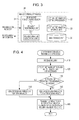
- FIG. 4 is a flowchart of a process of transmitting management information base (MIB) information in the exemplary embodiment
- FIG. 5 is a diagram illustrating exemplary MIB information transmitted from an image forming apparatus connected to a network serving as an apparatus manager, in the exemplary embodiment
- FIG. 6 is a diagram illustrating exemplary MIB information transmitted from an image forming apparatus connected to a network serving as a non-manager, in the exemplary embodiment
- FIGS. 7A to 7C are diagrams illustrating an exemplary data configuration of setting information stored in a setting-information storage unit according to the exemplary embodiment
- FIG. 8 is a diagram illustrating an exemplary setting screen in the ready-made setting mode in the exemplary embodiment
- FIG. 9 is a diagram illustrating an exemplary setting screen in the custom setting mode in the exemplary embodiment.
- FIG. 10 is a diagram illustrating an exemplary setting screen for setting information about alerts in the custom setting mode in the exemplary embodiment
- FIG. 11 is a diagram illustrating an exemplary setting screen for setting information about the remaining amounts of consumables in the custom setting mode in the exemplary embodiment
- FIG. 12 is a diagram illustrating an exemplary setting screen for setting information about counters in the custom setting mode in the exemplary embodiment
- FIG. 13 is a diagram illustrating an exemplary setting screen for setting other information in the custom setting mode in the exemplary embodiment
- FIG. 14 is a flowchart of another process of transmitting MIB information in the exemplary embodiment.
- FIG. 15 is a diagram illustrating another configuration of the network system according to the exemplary embodiment.
- FIG. 1 is a diagram illustrating the configuration of a network system including an image forming apparatus according to an exemplary embodiment of the present invention.
- FIG. 1 illustrates two network systems (hereinafter, simply referred to as “networks”) 10 a and 10 b illustrated as networks A and B, and an image forming apparatus 12 c .
- the network A has a configuration in which a user terminal 11 a , an image forming apparatus 12 a , and a management apparatus 13 a are connected to a network 14 a constituted, for example, by a local-area network (LAN).
- LAN local-area network
- the network B has a configuration in which a user terminal 11 b , an image forming apparatus 12 b , and a management apparatus 13 b are connected to a network 14 b constituted, for example, by a LAN.
- the image forming apparatus 12 c is connected to both of the networks 14 a and 14 b.
- the user terminal 11 a in the network A is implemented by using a personal computer (PC) or the like from which the image forming apparatus 12 a and the image forming apparatus 12 c may be used.
- the management apparatus 13 a manages the image forming apparatus 12 a and the image forming apparatus 12 c which are connected to the same network, i.e., the network 14 a .
- the management apparatus 13 a transmits an inquiry to the image forming apparatuses 12 a and 12 c , i.e., request for transmission of MIB (management information base) information, thereby receiving MIB information from the image forming apparatuses 12 to which the inquiry has been transmitted, and referring to the MIB information.
- MIB management information base
- SNMP Simple Network Management Protocol
- the management apparatus 13 serves as an SNMP manager, and the image forming apparatuses 12 serve as an SNMP agent.
- the network B has the same configuration as that of the network A, and will not be described.
- the management apparatus 13 a manages the image forming apparatus 12 c connected to the multiple networks. Therefore, the management apparatus 13 b manages the image forming apparatus 12 b , but not the image forming apparatus 12 c .
- each of the networks A and B has only one user terminal 11 and only one image forming apparatus 12 .
- the number of user terminals 11 and the number of image forming apparatuses 12 are not limited to one, and the network A does not necessarily include the same number of user terminals 11 or image forming apparatuses 12 as that in the network B.
- FIG. 2 is a diagram illustrating the hardware configuration of an image forming apparatus 30 according to the present exemplary embodiment.
- the image forming apparatus 30 corresponds to the image forming apparatus 12 c connected to multiple networks (two networks in FIG. 1 ) in FIG. 1 .
- the image forming apparatus 30 is a multi-function device having various functions, such as a print function, a copy function, and a scanner function, and is an apparatus including a computer.
- a central processing unit (CPU) 21 controls operations of various units included in the apparatus, such as a scanner 24 and a printer engine 26 , according to programs stored in a read-only memory (ROM) 29 .
- ROM read-only memory
- An address data bus 22 connects the various units which are targets of the control of the CPU 21 , to one another, and performs data communication.
- An operation panel 23 accepts an instruction given by a user, and displays information. In the present exemplary embodiment, the operation panel 23 is used to set setting information.
- the scanner 24 reads out a document which is set by a user, and accumulates it as electronic data in a hard disk drive (HDD) 25 or the like.
- the HDD 25 stores an electronic document or the like which is obtained by reading out a document by using the scanner 24 .
- the printer engine 26 prints an image on an output sheet in accordance with instructions from a control program executed by the CPU 21 .
- a random-access memory (RAM) 28 is used as a work memory used when programs are executed, or as a communication buffer used when electronic data is received or transmitted.
- the ROM 29 stores various programs for control of the apparatus, an SNMP agent, and the like. Execution of the various programs causes the components described below to perform predetermined functions.
- the image forming apparatus 30 includes multiple network interfaces (I/Fs) 27 .
- a network interface (I/F) 27 is connected to a network 14 , and is used for reception of a job, reception and transmission of an SNMP message, and the like which are performed through the network 14 .
- FIG. 2 illustrates an example in which two network interfaces (I/Fs) 27 a and 27 b are connected to the address data bus 22 in order that the two different networks 14 a and 14 b are connected to the respective network I/Fs 27 a and 27 b as illustrated in FIG. 1 .
- the image forming apparatuses 12 a and 12 b illustrated in FIG. 1 may have a configuration similar to that of the image forming apparatus 30 .
- Each of the image forming apparatuses 12 a and 12 b is connected to only one network, i.e., a corresponding one of the networks 14 a and 14 b . Therefore, each of the image forming apparatuses 12 a and 12 b may have only one network interface 27 .
- the management apparatus 13 may be implemented by using a hardware configuration of a general-purpose server of the related art. That is, the management apparatus 13 includes a CPU, a ROM, a RAM, a HDD, a network interface, and an input/output unit.
- FIG. 3 is a block diagram illustrating the configuration of the image forming apparatus 30 according to the present exemplary embodiment.
- the image forming apparatus 30 includes an SNMP agent function processor 31 , a setting-information setting processor 32 , a setting-information storage unit 33 , and an MIB storage unit 34 .
- the image forming apparatus 30 includes units for performing various functions, such as printing, which are provided by the image forming apparatus 30 . Components which are not used in the description of the present exemplary embodiment will not be described.
- the SNMP agent function processor 31 is a unit for causing the apparatus to function as an SNMP agent, and includes a request responding unit 311 and an MIB information generating unit 312 .
- the request responding unit 311 receives a request for transmission of MIB information via either one of the network interfaces 27 , thereby receiving the inquiry.
- the request responding unit 311 serves as a transmitting unit, and transmits MIB information generated by the MIB information generating unit 312 in response to the inquiry, through the network interface 27 through which the transmission request has been received.
- the MIB information generating unit 312 serves as a management-information generating unit.
- the MIB information generating unit 312 In response to the transmission request for MIB information which is received via either one of the network interfaces 27 by the request responding unit 311 , the MIB information generating unit 312 extracts information which is to be transmitted through the network interface 27 through which the transmission request has been received, in accordance with setting information from the MIB information, and generates MIB information to be transmitted.
- the setting-information setting processor 32 which serves as a setting-information generating unit generates setting information in accordance with a setting operation performed by a user, and registers it in the setting-information storage unit 33 .
- the components 31 and 32 in the image forming apparatus 30 are implemented through an operation which is performed in a cooperative manner by the computer included in the image forming apparatus 30 and programs executed by the CPU 21 included in the computer.
- the storage units 33 and 34 are implemented by using the HDD 25 included in the image forming apparatus 30 .
- Programs used in the present exemplary embodiment may be provided not only through a communication unit but also through a computer-readable recording medium, such as a Universal Serial Bus (USB) or a digital versatile disk-read only memory (DVD-ROM), by storing the programs in the computer-readable recording medium.
- a computer-readable recording medium such as a Universal Serial Bus (USB) or a digital versatile disk-read only memory (DVD-ROM)
- the programs provided through a communication unit or a recording medium are installed in the computer, and the CPU of the computer executes the programs one by one, achieving the various processes.
- the setting information when MIB information is to be transmitted as a response to the inquiry, all pieces of the MIB information corresponding to the inquiry are not necessarily transmitted.
- Information extracted from the MIB information in accordance with the setting information is generated as MIB information which is to be transmitted, and is transmitted through the network interface 27 through which the inquiry has been received.
- the setting information needs to be set before the image forming apparatus 30 transmits MIB information in response to a transmission request from a network. Before the setting information is described, an operation in the present exemplary embodiment will be described by using the flowchart illustrated in FIG. 4 .
- the network A connected to the network interface 27 a is a network serving as the apparatus manager, and the management apparatus A included in the network A operates as a management apparatus which manages the image forming apparatus C.
- the network interface 27 a connected to the network A serving as the apparatus manager is a network interface for the apparatus manager.
- the network B which is connected to the network interface 27 b for a non-manager, not for the apparatus manager, is a network as a non-manager.
- the management apparatus B included in the network B as a non-manager does not manage the image forming apparatus C.
- the setting-information storage unit 33 stores setting information describing whether each of the network interfaces 27 a and 27 b operates for the apparatus manager or for a non-manager.
- the request responding unit 311 of the SNMP agent function processor 31 in the image forming apparatus C receives an inquiry (transmission request for MIB information) via either one of the network interfaces 27 (in step 110 ), the request responding unit 311 specifies the network interface 27 through which the inquiry has been received (in step 120 ).
- the MIB information generating unit 312 If the network interface 27 through which the inquiry has been received is the network interface 27 a for the apparatus manager (YES in step 130 ), the MIB information generating unit 312 generates MIB information for the apparatus manager as MIB information which is to be transmitted (in step 140 ).
- the MIB information generated when the network interface 27 through which the inquiry has been received operates for the apparatus manager may be the same information as MIB information generated when an image forming apparatus has only one network interface 27 .
- the MIB information generating unit 312 If the network interface 27 through which the inquiry has been received is the network interface 27 b for a non-manager (NO in step 130 ), the MIB information generating unit 312 generates MIB information for a non-manager as MIB information which is to be transmitted (in step 150 ).
- the request responding unit 311 transmits the generated MIB information through the network interface 27 through which the inquiry has been received (in step 160 ). Specifically, when the management apparatus A has transmitted the inquiry, the management apparatus A receives the MIB information for the apparatus manager from the image forming apparatus C. When the management apparatus B has transmitted the inquiry, the management apparatus B receives the MIB information for a non-manager from the image forming apparatus C.
- FIG. 5 illustrates MIB information received by the management apparatus A from the image forming apparatus C, and MIB information received from the image forming apparatus A for reference.
- FIG. 6 illustrates MIB information received by the management apparatus B from the image forming apparatus C, and MIB information received from the image forming apparatus B for reference.
- the data configuration of the MIB information for the apparatus manager which is transmitted from the image forming apparatus C is similar to that from the image forming apparatus A having only one network interface.
- information about an error indicating that the image forming apparatus C does not operate due to an anomaly is information of which not only the user terminal A but also the user terminal B using the image forming apparatus C is to be informed. Therefore, information about the error is to be transmitted to all of the networks A and B.
- the administrator of each of the management apparatuses A and B who receives the MIB information may refer to the alert information included in the received MIB information, and may order the toner. That is, the toner may be ordered in a duplicate manner.
- the management apparatus 13 b in the network serving as a non-manager fails to detect information about consumables. Therefore, consumables are not ordered.
- the value of the remaining amount of toner which indicates insufficient toner is replaced with the value indicating the normal state (in which printing may be performed). Accordingly, while the user terminal 11 b in the network serving as a non-manager does not know that the image forming apparatus 12 c may fail to be continuously used due to insufficiency of consumables or the like, the user terminal 11 b continuously use the image forming apparatus 12 c . Consumables are ordered on the network A side, and are replaced. Therefore, the image forming apparatus 12 c is used without any trouble.
- the MIB information for a non-manager when the MIB information for a non-manager is to be generated, even in the case where the information prtAlertGroup in the MIB information has a value of markerSupplies ( 11 ) or finSupply ( 31 ), this information is not transmitted to a non-manager.
- the number added to an MIB symbol represents the last number of an object identifier (OID).
- the value of prtMarkerSuppliesLevel which indicates the remaining amount or the remaining life of a consumable item is changed to “ ⁇ 3” which is a value indicating that printing may be performed and being used for a consumable item whose remaining amount fails to be obtained.
- the value of finSupplyCurrentLevel which indicates the remaining amount of a consumable item in the finisher is also changed to “ ⁇ 3”.
- MIB information represent information about consumables.
- the information about consumables is included in information referred to in order to enable the image forming apparatus C to be continuously used.
- specific information specified as being transmitted only to the network serving as the apparatus manager such as the above-described information about consumables, is set in advance in the setting information described below.
- Non-specific information other than specific information may be transmitted to either of the network serving as the apparatus manager and a network serving as a non-manager.
- MIB information to be transmitted is different depending on whether or not the destination network serves as the apparatus manager.
- the setting information to be set in advance before the MIB information is transmitted in the present exemplary embodiment as described above will be described.
- the ready-made setting is a mode in which preset settings, such as a setting which determines which MIB information is to be transmitted, and a setting which determines whether or not the value is to be changed upon transmission, are employed for the apparatus manager and a non-manager. This is a mode using so-called initial settings.
- FIGS. 7A to 7C are diagrams illustrating an exemplary data configuration of the setting information stored in the setting-information storage unit 33 according to the present exemplary embodiment.
- FIG. 8 is a diagram illustrating an exemplary setting screen displayed on the operation panel 23 when a user selects the ready-made setting as the setting mode.
- the setting of the setting information using display screens illustrated in FIGS. 8 to 13 may be remotely performed, not from the operation panel 23 .
- FIGS. 1 and 2 the description is made by taking an image forming apparatus including two network interfaces, as an example.
- FIG. 8 illustrates a setting screen for setting the setting information for an image forming apparatus including three network interfaces, and specifically illustrates an exemplary setting screen in the ready-made setting mode.
- the ready-made setting it is only required that a user select which network interface operates for the apparatus manager.
- FIG. 8 an example is illustrated in which the network interface to which the address 172.16.123.1 is set is selected as one operating for the apparatus manager. Only one network interface operates for the apparatus manager. Therefore, the network interfaces of 172.16.123.2 and 172.16.123.3 are unconditionally selected as those operating for a non-manager.
- the information which is set from a setting screen is stored in setting mode information included in the setting information.
- the setting mode information includes a mode selected by a user (ready-made setting or custom setting) and identification information (address) of each of the network interfaces specified as operating for the apparatus manager or for a non-manager, as illustrated in FIG. 7A .
- information describing which piece of MIB information is to be transmitted is set in advance for the apparatus manager and a non-manager.
- pieces of MIB information are classified as alert information, information about the remaining amounts of consumables, counter information, and the other information, as illustrated in FIG. 7B .
- the present invention is not necessarily limited to this classification.
- use of classification is not necessary to manage MIB information.
- all of the pieces of MIB information are to be transmitted for the apparatus manager. Therefore, each of the classifications is set to “NOTIFY” which indicates that the MIB information is to be transmitted, for the apparatus manager.
- a piece of MIB information for a non-manager may be set as being not transmitted, or may be set as one whose value is to be changed.
- “NOT-NOTIFY” is set as illustrated in the classification “counter setting information”.
- the pieces of MIB information for a non-manager for which restriction on transmission of the information and modification of the value are set correspond to the specific information specified in advance through setting.
- values obtained from the units (controllers for toner, trays, and the like) of the image forming apparatus are transmitted only to the network interface operating for the apparatus manager, and are not transmitted to the network interfaces operating for a non-manager, or the values are modified and transmitted.
- pieces of MIB information corresponding to the non-specific information which is not the specific information it is determined whether or not transmission is to be performed, on the basis of the setting information in the ready-made setting information (such as “NOTIFY” and “NOT-NOTIFY”).
- the setting screen illustrated in FIG. 8 may be used not only as a setting screen for the ready-made setting but also as a mode selection screen in which the current setting mode is selected by selecting either one of buttons 51 and 52 for the ready-made setting and the custom setting.
- the custom setting will be described.
- the ready-made setting is a mode in which information which is initially set for the apparatus manager and a non-manager is applied as it is.
- the custom setting is a mode in which a user inputs individual settings for the apparatus manager and a non-manager, such as a setting determining which piece of MIB information is to be transmitted, and a setting about pieces of MIB information whose values are to be modified.
- FIG. 9 illustrates a setting screen for setting the setting information for an image forming apparatus including three network interfaces, and particularly illustrates a setting screen for the custom setting.
- a user selects a network interface on which setting is performed, and performs setting as follows.
- FIG. 10 illustrates an exemplary setting screen displayed after the network interface of 172.16.123.2 is selected as a target to be set, when a button 44 for setting alerts is selected in FIG. 9 .
- MIB symbols corresponding to the MIB information about alerts are displayed. Therefore, a user selects a selection button 48 corresponding to an MIB symbol which is to be transmitted (or “none specified”) from the screen, thereby selecting pieces of MIB information to be transmitted.
- pieces of MIB information which are to be transmitted may be selected, or pieces of MIB information which are not to be transmitted may be selected.
- FIG. 11 illustrates an exemplary setting screen displayed after the network interface of 172.16.123.2 is selected as a target to be set, when a button 45 for setting the remaining amounts of consumables is selected in FIG. 9 .
- settings are made which, when the remaining amount becomes insufficient, determine which operation from the following operations is to be performed: an operation in which the actual value indicating the remaining amount is transmitted (selection of “normal”); and an operation in which information describing that printing may be performed is always transmitted (selection of “printing state”).
- FIG. 13 illustrates an exemplary setting screen displayed after the network interface of 172.16.123.2 is selected as a target to be set, when a button 47 for setting other items is selected in FIG. 9 .
- this screen settings which describe that 0 is always transmitted as the value of the illustrated OIDs are made for other items.
- the setting screen illustrated in FIG. 13 is an example, and various types of settings for MIB information may be made for other items.
- the setting from the above-described setting screens is performed on each of the network interfaces, and the setting information for each of the network interfaces is stored in a corresponding one of item areas corresponding to custom setting information illustrated in FIG. 7C .
- only one network interface operates for the apparatus manager, and the other network interfaces operate for non-managers. Therefore, in the case of the custom setting, a network interface which is set as one through which the specific information is transmitted may be automatically recognized as one operating for the apparatus manager. Alternatively, as in the ready-made setting, a user may explicitly specify the network interface operating for the apparatus manager. In either case, the specific information needs to be transmitted to only one network interface. Therefore, a process for preventing a setting which causes the specific information to be transmitted to multiple network interfaces from being made may be performed by the setting-information setting processor 32 .
- a process of transmitting the MIB information in the present exemplary embodiment which is performed in consideration of the ready-made setting and the custom setting will be described by using the flowchart illustrated in FIG. 14 .
- the same processes as those in FIG. 4 are designated with identical reference characters, and are not described as appropriate.
- the request responding unit 311 When the request responding unit 311 receives an inquiry via either one of the network interfaces 27 (in step 110 ), the request responding unit 311 specifies the network interface 27 through which the inquiry has been received (in step 120 ).
- the MIB information generating unit 312 refers to the setting mode information stored in the setting-information storage unit 33 . If the MIB information generating unit 312 determines that the currently selected setting mode is the ready-made setting (YES in step 210 ), and if the network interface 27 through which the inquiry has been received is a network interface operating for the apparatus manager (YES in step 130 ), the MIB information generating unit 312 refers to the settings for the apparatus manager in the ready-made setting information, extracts the corresponding pieces of MIB information, and generates MIB information for the apparatus manager (in step 140 ).
- the MIB information generating unit 312 refers to settings for a non-manger in the ready-made setting information.
- the MIB information generating unit 312 extracts the corresponding pieces of MIB information excluding the specific information which is not to be transmitted, and modifies values of pieces of MIB information, thereby generating MIB information for a non-manager (in step 150 ).
- the MIB information generating unit 312 determines that the currently selected setting mode is the custom setting, by referring to the setting mode information stored in the setting-information storage unit 33 (NO in step 210 ), the MIB information generating unit 312 refers to information corresponding to the network interface through which the inquiry has been received, in the custom setting information, extracts the corresponding pieces of MIB information, and generates MIB information which is to be transmitted (in step 220 ).
- the request responding unit 311 transmits the generated MIB information through the network interface 27 through which the inquiry has been received (in step 160 ).
- information which is to be transmitted to only one management apparatus 13 is transmitted to only one management apparatus 13 , avoiding duplicate orders of consumables, or the like.
- FIG. 15 is a diagram illustrating a second configuration of the network system according to the present exemplary embodiment.
- this system omits the management apparatus 13 b from the network B, and the network 14 a is connected to the network 14 b via a router 5 , whereby the management apparatus 13 a monitors all of the image forming apparatuses 12 a , 12 b , and 12 c included in the networks A and B.
- the management apparatus 13 a receives not only MIB information transmitted from the network interface 27 a of the image forming apparatus 12 c but also MIB information transmitted from the network interface 27 b via the router 5 .
- the management apparatus 13 a does not receive duplicate information about consumables of the image forming apparatus 12 c.
- the description is made by taking information about consumables as exemplary MIB information which is set as the specific information and which is transmitted to only one management apparatus. Other pieces of MIB information may be included in the specific information.
- the custom setting enables information describing which MIB information is to be transmitted, to be set as appropriate, enabling easy setting according to the operation of the network system.
Landscapes
- Engineering & Computer Science (AREA)
- Theoretical Computer Science (AREA)
- General Engineering & Computer Science (AREA)
- General Physics & Mathematics (AREA)
- Human Computer Interaction (AREA)
- Physics & Mathematics (AREA)
- Signal Processing (AREA)
- Computer Networks & Wireless Communication (AREA)
- Computer Security & Cryptography (AREA)
- Accessory Devices And Overall Control Thereof (AREA)
- Control Or Security For Electrophotography (AREA)
- Small-Scale Networks (AREA)
- Facsimiles In General (AREA)
- Computer And Data Communications (AREA)
Abstract
Description
Claims (7)
Applications Claiming Priority (2)
| Application Number | Priority Date | Filing Date | Title |
|---|---|---|---|
| JP2014-053316 | 2014-03-17 | ||
| JP2014053316A JP6135564B2 (en) | 2014-03-17 | 2014-03-17 | Image forming apparatus and program |
Publications (2)
| Publication Number | Publication Date |
|---|---|
| US20150261476A1 US20150261476A1 (en) | 2015-09-17 |
| US9792078B2 true US9792078B2 (en) | 2017-10-17 |
Family
ID=54068934
Family Applications (1)
| Application Number | Title | Priority Date | Filing Date |
|---|---|---|---|
| US14/467,810 Expired - Fee Related US9792078B2 (en) | 2014-03-17 | 2014-08-25 | Image forming apparatus for transmitting management information via a plurality of network interfaces |
Country Status (3)
| Country | Link |
|---|---|
| US (1) | US9792078B2 (en) |
| JP (1) | JP6135564B2 (en) |
| CN (1) | CN104932843B (en) |
Families Citing this family (3)
| Publication number | Priority date | Publication date | Assignee | Title |
|---|---|---|---|---|
| JP6413495B2 (en) * | 2014-08-29 | 2018-10-31 | セイコーエプソン株式会社 | Information processing method and recording system |
| JP5765474B1 (en) * | 2014-09-24 | 2015-08-19 | 富士ゼロックス株式会社 | Information processing apparatus and information processing program |
| JP2024063812A (en) * | 2022-10-27 | 2024-05-14 | キヤノン株式会社 | Program and setting system |
Citations (8)
| Publication number | Priority date | Publication date | Assignee | Title |
|---|---|---|---|---|
| JPH11355332A (en) | 1998-04-07 | 1999-12-24 | Ricoh Co Ltd | Network management system and managed device management method |
| JP2001256029A (en) | 2000-03-13 | 2001-09-21 | Seiko Epson Corp | Printing system, printing device, and print control device |
| US20070083797A1 (en) * | 2005-09-26 | 2007-04-12 | Brother Kogyo Kabushiki Kaisha | Network System, Printing Device, and Control Program for Printing Device |
| JP2009137299A (en) | 2008-12-05 | 2009-06-25 | Brother Ind Ltd | Printing apparatus, printing apparatus control program, and network system |
| US20110131310A1 (en) * | 2009-11-30 | 2011-06-02 | Canon Kabushiki Kaisha | Multi-homed communication apparatus, and control method and storage medium therefor |
| US20140293325A1 (en) * | 2013-04-02 | 2014-10-02 | Ricoh Company, Ltd. | Click-to-print system, apparatus and method |
| US20150062626A1 (en) * | 2013-08-27 | 2015-03-05 | Canon Kabushiki Kaisha | Management apparatus, control method therefor, and non-transitory computer-readable medium |
| US20150188611A1 (en) * | 2013-12-27 | 2015-07-02 | Brother Kogyo Kabushiki Kaisha | Communication Device |
Family Cites Families (8)
| Publication number | Priority date | Publication date | Assignee | Title |
|---|---|---|---|---|
| JPH11194913A (en) * | 1997-12-26 | 1999-07-21 | Ricoh Co Ltd | Network printer |
| JP2003276284A (en) * | 2002-03-26 | 2003-09-30 | Kyocera Mita Corp | Image forming apparatus connected to network |
| JP2004145570A (en) * | 2002-10-23 | 2004-05-20 | Konica Minolta Holdings Inc | Image forming apparatus and ordering system for material of image forming apparatus |
| JP4141332B2 (en) * | 2003-06-19 | 2008-08-27 | 京セラミタ株式会社 | Image forming apparatus |
| JP2005262665A (en) * | 2004-03-18 | 2005-09-29 | Kyocera Mita Corp | Image forming apparatus |
| JP2006173852A (en) * | 2004-12-14 | 2006-06-29 | Konica Minolta Business Technologies Inc | Image forming apparatus |
| JP4404215B2 (en) * | 2005-08-12 | 2010-01-27 | ブラザー工業株式会社 | Image forming apparatus, management apparatus, network system, control program for image forming apparatus, and control program for management apparatus |
| JP2013101600A (en) * | 2011-10-19 | 2013-05-23 | Ricoh Co Ltd | Management system, electronic apparatus, electronic apparatus control method and program |
-
2014
- 2014-03-17 JP JP2014053316A patent/JP6135564B2/en active Active
- 2014-08-25 US US14/467,810 patent/US9792078B2/en not_active Expired - Fee Related
- 2014-10-09 CN CN201410528280.3A patent/CN104932843B/en active Active
Patent Citations (8)
| Publication number | Priority date | Publication date | Assignee | Title |
|---|---|---|---|---|
| JPH11355332A (en) | 1998-04-07 | 1999-12-24 | Ricoh Co Ltd | Network management system and managed device management method |
| JP2001256029A (en) | 2000-03-13 | 2001-09-21 | Seiko Epson Corp | Printing system, printing device, and print control device |
| US20070083797A1 (en) * | 2005-09-26 | 2007-04-12 | Brother Kogyo Kabushiki Kaisha | Network System, Printing Device, and Control Program for Printing Device |
| JP2009137299A (en) | 2008-12-05 | 2009-06-25 | Brother Ind Ltd | Printing apparatus, printing apparatus control program, and network system |
| US20110131310A1 (en) * | 2009-11-30 | 2011-06-02 | Canon Kabushiki Kaisha | Multi-homed communication apparatus, and control method and storage medium therefor |
| US20140293325A1 (en) * | 2013-04-02 | 2014-10-02 | Ricoh Company, Ltd. | Click-to-print system, apparatus and method |
| US20150062626A1 (en) * | 2013-08-27 | 2015-03-05 | Canon Kabushiki Kaisha | Management apparatus, control method therefor, and non-transitory computer-readable medium |
| US20150188611A1 (en) * | 2013-12-27 | 2015-07-02 | Brother Kogyo Kabushiki Kaisha | Communication Device |
Non-Patent Citations (1)
| Title |
|---|
| Communication dated Nov. 8, 2016, from the Japanese Patent Office in counterpart application No. 2014-053316, drafted Nov. 4, 2016. |
Also Published As
| Publication number | Publication date |
|---|---|
| JP2015174368A (en) | 2015-10-05 |
| CN104932843B (en) | 2018-06-26 |
| JP6135564B2 (en) | 2017-05-31 |
| US20150261476A1 (en) | 2015-09-17 |
| CN104932843A (en) | 2015-09-23 |
Similar Documents
| Publication | Publication Date | Title |
|---|---|---|
| US9253337B2 (en) | Program, image processing apparatus, and image processing system | |
| US11570324B2 (en) | Printing apparatus capable of counting the number of times of printing, method for controlling printing apparatus, and storage medium | |
| US20150070719A1 (en) | Image forming apparatus and image forming system | |
| US8947708B2 (en) | Information processing apparatus, method for controlling an information processing apparatus, and image forming system | |
| US9792078B2 (en) | Image forming apparatus for transmitting management information via a plurality of network interfaces | |
| US9310739B2 (en) | Printing apparatus, method, and storage medium for controlling the display of an aggregation result of a number of printed pages | |
| US9262114B2 (en) | Information apparatus and information processing system | |
| US20170039011A1 (en) | Printing system, printing apparatus and server used in the system, management method of print data, and medium | |
| US10101954B2 (en) | Job processing apparatus that manages history information, method of controlling the same, and storage medium | |
| US9197488B2 (en) | Information processing apparatus, information processing method, and non-transitory computer readable medium | |
| JP6324571B2 (en) | Printing apparatus, method and program for counting the number of times of printing | |
| US20250355600A1 (en) | Image forming apparatus, method for controlling the same, and storage medium | |
| US20240377996A1 (en) | Information processing system, information processing method, and non-transitory computer readable medium | |
| JP6919034B2 (en) | Printing device, setting method and program | |
| JP6532569B2 (en) | Printing device, control method for printing device, and program | |
| JP6748754B2 (en) | Printing device, setting method, and program | |
| JP2022130458A (en) | Printing device, method and program | |
| US9350891B2 (en) | Image forming system, image forming apparatus, and non-transitory computer readable recording medium storing a setup program | |
| JP2023093471A (en) | printer | |
| JP2010113553A (en) | Log information management system and log information management device | |
| JP2012068994A (en) | Terminal device, output system and program |
Legal Events
| Date | Code | Title | Description |
|---|---|---|---|
| AS | Assignment |
Owner name: FUJI XEROX CO., LTD., JAPAN Free format text: ASSIGNMENT OF ASSIGNORS INTEREST;ASSIGNOR:YAMADA, KENTARO;REEL/FRAME:033603/0884 Effective date: 20140620 |
|
| STCF | Information on status: patent grant |
Free format text: PATENTED CASE |
|
| MAFP | Maintenance fee payment |
Free format text: PAYMENT OF MAINTENANCE FEE, 4TH YEAR, LARGE ENTITY (ORIGINAL EVENT CODE: M1551); ENTITY STATUS OF PATENT OWNER: LARGE ENTITY Year of fee payment: 4 |
|
| AS | Assignment |
Owner name: FUJIFILM BUSINESS INNOVATION CORP., JAPAN Free format text: CHANGE OF NAME;ASSIGNOR:FUJI XEROX CO., LTD.;REEL/FRAME:058287/0056 Effective date: 20210401 |
|
| FEPP | Fee payment procedure |
Free format text: MAINTENANCE FEE REMINDER MAILED (ORIGINAL EVENT CODE: REM.); ENTITY STATUS OF PATENT OWNER: LARGE ENTITY |
|
| LAPS | Lapse for failure to pay maintenance fees |
Free format text: PATENT EXPIRED FOR FAILURE TO PAY MAINTENANCE FEES (ORIGINAL EVENT CODE: EXP.); ENTITY STATUS OF PATENT OWNER: LARGE ENTITY |
|
| STCH | Information on status: patent discontinuation |
Free format text: PATENT EXPIRED DUE TO NONPAYMENT OF MAINTENANCE FEES UNDER 37 CFR 1.362 |
|
| FP | Lapsed due to failure to pay maintenance fee |
Effective date: 20251017 |