US9784950B2 - Zoom lens system and electronic imaging apparatus using the same - Google Patents
Zoom lens system and electronic imaging apparatus using the same Download PDFInfo
- Publication number
- US9784950B2 US9784950B2 US14/426,558 US201314426558A US9784950B2 US 9784950 B2 US9784950 B2 US 9784950B2 US 201314426558 A US201314426558 A US 201314426558A US 9784950 B2 US9784950 B2 US 9784950B2
- Authority
- US
- United States
- Prior art keywords
- lens group
- lens
- positive
- sub
- negative
- Prior art date
- Legal status (The legal status is an assumption and is not a legal conclusion. Google has not performed a legal analysis and makes no representation as to the accuracy of the status listed.)
- Active
Links
Images


Classifications
-
- G—PHYSICS
- G02—OPTICS
- G02B—OPTICAL ELEMENTS, SYSTEMS OR APPARATUS
- G02B13/00—Optical objectives specially designed for the purposes specified below
- G02B13/001—Miniaturised objectives for electronic devices, e.g. portable telephones, webcams, PDAs, small digital cameras
- G02B13/009—Miniaturised objectives for electronic devices, e.g. portable telephones, webcams, PDAs, small digital cameras having zoom function
-
- G—PHYSICS
- G02—OPTICS
- G02B—OPTICAL ELEMENTS, SYSTEMS OR APPARATUS
- G02B15/00—Optical objectives with means for varying the magnification
- G02B15/14—Optical objectives with means for varying the magnification by axial movement of one or more lenses or groups of lenses relative to the image plane for continuously varying the equivalent focal length of the objective
- G02B15/144—Optical objectives with means for varying the magnification by axial movement of one or more lenses or groups of lenses relative to the image plane for continuously varying the equivalent focal length of the objective having four groups only
- G02B15/1441—Optical objectives with means for varying the magnification by axial movement of one or more lenses or groups of lenses relative to the image plane for continuously varying the equivalent focal length of the objective having four groups only the first group being positive
- G02B15/144113—Optical objectives with means for varying the magnification by axial movement of one or more lenses or groups of lenses relative to the image plane for continuously varying the equivalent focal length of the objective having four groups only the first group being positive arranged +-++
-
- G—PHYSICS
- G02—OPTICS
- G02B—OPTICAL ELEMENTS, SYSTEMS OR APPARATUS
- G02B15/00—Optical objectives with means for varying the magnification
- G02B15/14—Optical objectives with means for varying the magnification by axial movement of one or more lenses or groups of lenses relative to the image plane for continuously varying the equivalent focal length of the objective
- G02B15/16—Optical objectives with means for varying the magnification by axial movement of one or more lenses or groups of lenses relative to the image plane for continuously varying the equivalent focal length of the objective with interdependent non-linearly related movements between one lens or lens group, and another lens or lens group
- G02B15/163—Optical objectives with means for varying the magnification by axial movement of one or more lenses or groups of lenses relative to the image plane for continuously varying the equivalent focal length of the objective with interdependent non-linearly related movements between one lens or lens group, and another lens or lens group having a first movable lens or lens group and a second movable lens or lens group, both in front of a fixed lens or lens group
- G02B15/167—Optical objectives with means for varying the magnification by axial movement of one or more lenses or groups of lenses relative to the image plane for continuously varying the equivalent focal length of the objective with interdependent non-linearly related movements between one lens or lens group, and another lens or lens group having a first movable lens or lens group and a second movable lens or lens group, both in front of a fixed lens or lens group having an additional fixed front lens or group of lenses
- G02B15/173—Optical objectives with means for varying the magnification by axial movement of one or more lenses or groups of lenses relative to the image plane for continuously varying the equivalent focal length of the objective with interdependent non-linearly related movements between one lens or lens group, and another lens or lens group having a first movable lens or lens group and a second movable lens or lens group, both in front of a fixed lens or lens group having an additional fixed front lens or group of lenses arranged +-+
-
- G—PHYSICS
- G02—OPTICS
- G02B—OPTICAL ELEMENTS, SYSTEMS OR APPARATUS
- G02B15/00—Optical objectives with means for varying the magnification
- G02B15/14—Optical objectives with means for varying the magnification by axial movement of one or more lenses or groups of lenses relative to the image plane for continuously varying the equivalent focal length of the objective
- G02B15/16—Optical objectives with means for varying the magnification by axial movement of one or more lenses or groups of lenses relative to the image plane for continuously varying the equivalent focal length of the objective with interdependent non-linearly related movements between one lens or lens group, and another lens or lens group
- G02B15/177—Optical objectives with means for varying the magnification by axial movement of one or more lenses or groups of lenses relative to the image plane for continuously varying the equivalent focal length of the objective with interdependent non-linearly related movements between one lens or lens group, and another lens or lens group having a negative front lens or group of lenses
-
- H04N5/2254—
Definitions
- the present invention relates to a zoom lens system and an electronic imaging apparatus using such a zoom lens system.
- Patent Literature Nos. 1 through 3 each disclose a zoom lens system, having four lens groups, configured of a positive first lens group, a negative second lens group, a positive third lens group, and a positive fourth lens group, in that order from the object side, wherein the first lens group is divided into a front sub-lens group and a rear sub-lens group, and the rear sub-lens group of the first lens group serves as a focusing lens group that is moved during focusing.
- the Abbe number setting of the lens elements that configure the front sub-lens group and the rear sub-lens group of the first lens group is unsuitable, it becomes difficult to correct various aberrations such as axial chromatic aberration and lateral chromatic aberration, thereby deteriorating the optical quality.
- Patent Literature 1 Japanese Unexamined Patent Publication No. H06-51202
- Patent Literature 2 Japanese Unexamined Patent Publication No. 2002-162564
- Patent Literature 3 Japanese Unexamined Patent Publication No. 2004-85846
- the present invention has been devised with consideration to the above problems, and provides a zoom lens system having a miniaturized and reduced-in-weight focusing lens group that can carry out a rapid and quiet focusing operation while achieving a superior optical quality by favorably correcting various aberrations such as axial chromatic aberration and lateral chromatic aberration, and an electronic imaging apparatus using such a zoom lens system.
- a zoom lens system including a positive first lens group, a negative second lens group, a positive third lens group, and a positive fourth lens group, in that order from the object side, wherein at least the second lens group and the third lens group are moved during zooming from the short focal length extremity to the long focal length extremity.
- the first lens group includes a positive first sub-lens group which does not move during a focusing operation, and a positive second sub-lens group, serving as a focusing lens group, which moves during the focusing operation, in that order from the object side.
- the first sub-lens group is formed from at least one negative lens element
- the second sub-lens group is formed from a positive single lens element
- the following conditions (1) and (2) are satisfied: 6021 ⁇ d1b ⁇ 75 (1), and ⁇ d1a ⁇ 24 (2), wherein ⁇ d1b designates the Abbe number at the d-line of the positive single lens element of the second sub-lens group, and vdla designates the Abbe number at the d-line of the at least one negative lens element within the first sub-lens group.
- condition (1′) it is desirable for the following condition (1′) to be satisfied from within the range of condition (1): 68 ⁇ d1b ⁇ 75 (1′).
- SP1b designates the shape factor of the positive single lens element of the second sub-lens group
- SP1b (R2+R1)/(R2 ⁇ R1)
- R1 designates the radius of curvature of the surface on the object side of the positive single lens element of the second sub-lens group
- R2 designates the radius of curvature of the surface on the image side of the positive single lens element of the second sub-lens group.
- condition (3′) it is desirable for the following condition (3′) to be satisfied from within the range of condition (3): 1.15 ⁇ SP1b ⁇ 1.55 (3′).
- a zoom lens system including a positive first lens group, a negative second lens group, a positive third lens group, and a positive fourth lens group, in that order from the object side, wherein at least the second lens group and the third lens group are moved during zooming from the short focal length extremity to the long focal length extremity.
- the first lens group includes a positive first sub-lens group provided with at least one negative lens element, and a positive second sub-lens group formed from a positive single lens element, in that order from the object side, and the following condition (2′) is satisfied: ⁇ d1a ⁇ 22.85 (2′), wherein ⁇ d 1 a designates the Abbe number at the d-line of the negative lens element that is positioned closest to the object side within the first sub-lens group.
- the second lens group can be configured of a negative lens element having a concave surface on the image side, a negative lens element having a concave surface on the image side, and a cemented lens including a positive lens element and a negative lens element, in that order from the object side.
- each of the positive lens element and the negative lens element, which constitute the cemented lens of the second lens group to have a convex surface on the object side thereof and a concave surface on the image side thereof.
- the zoom lens system of the present invention it is desirable for the zoom lens system of the present invention to satisfy the following conditions (4) and (5): ⁇ 0.3 ⁇ f 2/ft ⁇ 0.18 (4), and 4.5 ⁇ TL/ST 2 ⁇ 5.5 (5), wherein f2designates the focal length of the second lens group, ft designates the focal length of the entire lens system at the long focal length extremity, TL designates the entire length of the lens system at the long focal length extremity (the distance between the surface closest to the object side of the first lens group and the imaging plane), and ST2designates a movement amount of the second lens group during zooming from the short focal length extremity to the long focal length extremity.
- the fourth lens group in the zoom lens system of the present invention, it is desirable for the fourth lens group to include a third sub-lens group provided with at least one positive lens element and negative lens element, and a fourth sub-lens group provided with at least one positive lens element and negative lens element, in that order from the object side, and wherein the following condition (6) is satisfied: 0.15 ⁇ D 4/ LD 4 ⁇ 0.35 (6), wherein D4designates an air-distance between the third sub-lens group and the fourth sub-lens group (the distance between the surface closest to the image side of the third sub-lens group to the surface closest to the object side of the fourth sub-lens group), and LD4designates the distance between a surface closest to the object side of the fourth lens group to a surface closest to the image side thereof.
- An electronic imaging apparatus of the present invention is provided with any of the above-described the zoom lens systems, and an imaging device which converts an image formed by the zoom lens system into electrical signals.
- a zoom lens system having a miniaturized and reduced-in-weight focusing lens group that can carry out a rapid and quiet focusing operation while achieving a superior optical quality by favorably correcting various aberrations such as axial chromatic aberration and lateral chromatic aberration, and an electronic imaging apparatus using such a zoom lens system, are achieved.
- FIG. 1 shows a lens arrangement of a first numerical embodiment of a zoom lens system, according to the present invention, at the long focal length extremity when focused on an object at infinity.
- FIG. 2 shows various aberrations that occurred in the lens arrangement of FIG. 1 .
- FIG. 3 shows lateral aberrations that occurred in the lens arrangement of FIG. 1 .
- FIG. 4 shows a lens arrangement of the first numerical embodiment of a zoom lens system at the short focal length extremity when focused on an object at infinity.
- FIG. 5 shows various aberrations that occurred in the lens arrangement of FIG. 4 .
- FIG. 6 shows lateral aberrations that occurred in the lens arrangement of FIG. 4 .
- FIG. 7 shows a lens arrangement of a second numerical embodiment of a zoom lens system, according to the present invention, at the long focal length extremity when focused on an object at infinity.
- FIG. 8 shows various aberrations that occurred in the lens arrangement of FIG. 7 .
- FIG. 9 shows lateral aberrations that occurred in the lens arrangement of FIG. 7 .
- FIG. 10 shows a lens arrangement of the second numerical embodiment of a zoom lens system at the short focal length extremity when focused on an object at infinity.
- FIG. 11 shows various aberrations that occurred in the lens arrangement of FIG. 10 .
- FIG. 12 shows lateral aberrations that occurred in the lens arrangement of FIG. 10 .
- FIG. 13 shows a lens arrangement of a third numerical embodiment of a zoom lens system, according to the present invention, at the long focal length extremity when focused on an object at infinity.
- FIG. 14 shows various aberrations that occurred in the lens arrangement of FIG. 13 .
- FIG. 15 shows lateral aberrations that occurred in the lens arrangement of FIG. 13 .
- FIG. 16 shows a lens arrangement of the third numerical embodiment of a zoom lens system at the short focal length extremity when focused on an object at infinity.
- FIG. 17 shows various aberrations that occurred in the lens arrangement of FIG. 16 .
- FIG. 18 shows lateral aberrations that occurred in the lens arrangement of FIG. 16 .
- FIG. 19 shows a lens arrangement of a fourth numerical embodiment of a zoom lens system, according to the present invention, at the long focal length extremity when focused on an object at infinity.
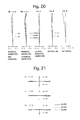
- FIG. 20 shows various aberrations that occurred in the lens arrangement of FIG. 19 .
- FIG. 21 shows lateral aberrations that occurred in the lens arrangement of FIG. 19 .
- FIG. 22 shows a lens arrangement of the fourth numerical embodiment of a zoom lens system at the short focal length extremity when focused on an object at infinity.
- FIG. 23 shows various aberrations that occurred in the lens arrangement of FIG. 22 .
- FIG. 24 shows lateral aberrations that occurred in the lens arrangement of FIG. 22 .
- FIG. 25 shows a lens arrangement of a fifth numerical embodiment of a zoom lens system, according to the present invention, at the long focal length extremity when focused on an object at infinity.
- FIG. 26 shows various aberrations that occurred in the lens arrangement of FIG. 25 .
- FIG. 27 shows lateral aberrations that occurred in the lens arrangement of FIG. 25 .
- FIG. 28 shows a lens arrangement of the fifth numerical embodiment of a zoom lens system at the short focal length extremity when focused on an object at infinity.
- FIG. 29 shows various aberrations that occurred in the lens arrangement of FIG. 28 .
- FIG. 30 shows lateral aberrations that occurred in the lens arrangement of FIG. 28 .
- FIG. 31 shows a lens arrangement of a sixth numerical embodiment of a zoom lens system, according to the present invention, at the long focal length extremity when focused on an object at infinity.
- FIG. 32 shows various aberrations that occurred in the lens arrangement of FIG. 31 .
- FIG. 33 shows lateral aberrations that occurred in the lens arrangement of FIG. 31 .
- FIG. 34 shows a lens arrangement of the sixth numerical embodiment of a zoom lens system at the short focal length extremity when focused on an object at infinity.
- FIG. 35 shows various aberrations that occurred in the lens arrangement of FIG. 34 .
- FIG. 36 shows lateral aberrations that occurred in the lens arrangement of FIG. 34 .
- FIG. 37 shows a zoom path of the zoom lens system, according to the present invention.
- the zoom lens system of the illustrated embodiments is configured of a positive first lens group G 1 , a negative second lens group G 2 , a positive third lens group G 3 , and a positive fourth lens group G 4 , in that order from the object side.
- the first lens group G 1 is configured of a positive first sub-lens group G 1 a and a positive second sub-lens group G 1 b , in that order from the object side.
- the fourth lens group G 4 is configured of a positive third sub-lens group G 4 a and a positive fourth sub-lens group G 4 b , in that order from the object side.
- a diaphragm S which is positioned between the second lens group G 2 and the third lens group G 3 moves integrally with the third lens group G 3 . ‘I’ designates the imaging plane.
- the distance between the first lens group G 1 and the second lens group G 2 increases, the distance between the second lens group G 2 and the third lens group G 3 decreases, and the distance between the third lens group G 3 and the fourth lens group G 4 decreases.
- the distance between the first sub-lens group G 1 a and the second sub-lens group G 1 b does not change, and the distance between the third sub-lens group G 4 a and the fourth sub-lens group G 4 b does not change.
- the first lens group G 1 (the first sub-lens group G 1 a and the second sub-lens group G 1 b ) and the fourth lens group G 4 (the third sub-lens group G 4 a and the fourth sub-lens group G 4 b ) remain stationary relative to the image plane I (do not move in the optical axis direction).
- first lens group G 1 (the first sub-lens group G 1 a and the second sub-lens group G 1 b ) and the fourth lens group G 4 (the third sub-lens group G 4 a and the fourth sub-lens group G 4 b ) move in the optical axis direction upon zooming from the short focal length extremity to the long focal length extremity.
- the second lens group G 2 monotonically moves toward the image side upon zooming from the short focal length extremity to the long focal length extremity.
- the first sub-lens group G 1 a does not move during focusing
- the second sub-lens group G 1 b is a focusing lens group which moves during focusing.
- the second sub-lens group G 1 b moves toward the object side upon focusing on an object from infinity to an object at a finite distance.
- the first sub-lens group G 1 a of the first lens group G 1 is configured of a cemented lens having a negative lens element 11 and a positive lens element 12 , in that order from the object side.
- the negative lens element 11 is formed from a high dispersion glass material (e.g., OHARA S-NPH1 of Ohara Inc.) having an Abbe number of 22.8 at the d-line.
- the second sub-lens group G 1 b of the first lens group G 1 is configured of a positive single lens element 13 .
- the positive single lens element 13 is formed from a glass material (e.g., OHARA S-FSL5 of Ohara Inc.) having anomalous dispersion characteristics such that the Abbe number thereof is 70.2 at the d-line, and having a low specific gravity of 2.46.
- the second lens group G 2 is configured of a negative lens element (negative lens element having a concave surface on the image side) 21 , a negative lens element (negative lens element having a concave surface on the image side) 22 , and a cemented lens configured of a positive lens element 23 and a negative lens element 24 , in that order from the object side.
- the third lens group G 3 is configured of a cemented lens configured of a positive lens element 31 and a negative lens element 32 , in that order from the object side.
- the third sub-lens group G 4 a of the fourth lens group G 4 is configured of a positive lens element 41 , and a cemented lens configured of a positive lens element 42 and a negative lens element 43 , in that order from the object side.
- the fourth sub-lens group G 4 b of the fourth lens group G 4 is configured of a positive lens element 44 and a negative lens element 45 , in that order from the object side.
- the first lens group G 1 and the fourth lens group G 4 are stationary relative to the image plane I during zooming from the short focal length extremity to the long focal length extremity, while mainly the second lens group G 2 performs zooming and the third lens group G 3 compensates for image-surface fluctuations that occur during zooming.
- the first lens group G 1 is divided into the first sub-lens group G 1 a and the second sub-lens group G 1 b ; the first sub-lens group G 1 a is configured to be immovable during focusing, and the second sub-lens group G 1 b is configured as a focusing lens group that moves during focusing. Accordingly, the overall length of the lens system does not change during zooming and focusing, so that a zoom lens system, in which the f-number variation is small, can be achieved.
- each zoom lens system of the illustrated embodiments by configuring the second lens group G 2 with a negative lens element (negative lens element having a concave surface on the image side) 21 , a negative lens element (negative lens element having a concave surface on the image side) 22 , and a cemented lens configured of a positive lens element 23 and a negative lens element 24 , in that order from the object side, coma and astigmatism can be favorably corrected over the entire zooming range so that a superior optical quality can be achieved. Furthermore, by providing a concave surface facing the image side on each of the positive lens element 23 and the negative lens element 24 , which constitute a cemented lens, coma and astigmatism can be corrected even more favorably.
- the fourth lens group G 4 is configured of the positive third sub-lens group G 4 a and the positive fourth sub-lens group G 4 b , in that order from the object side.
- the third sub-lens group G 4 a is configured of two positive lens elements 41 and 42 , and one negative lens element 43 .
- the fourth sub-lens group G 4 b is configured of one positive lens element 44 and one negative lens element 45 .
- the focusing lens group can be miniaturized and reduced in weight to carry out a rapid and quiet focusing operation while successfully achieving a superior optical quality by favorably correcting various aberrations such as axial chromatic aberration and lateral chromatic aberration.
- Condition (1) specifies the Abbe number at the d-line of the positive single lens element 13 of the second sub-lens group G 1 b .
- the focusing lens group can be miniaturized and reduced in weight to carry out a rapid and quiet focusing operation while achieving a superior optical quality by favorably correcting various aberrations such as axial chromatic aberration and lateral chromatic aberration, particularly at the long focal length extremity.
- the first sub-lens group G 1 a is configured of a cemented lens having a negative lens element 11 and a positive lens element 12 , in that order from the object side.
- two or more negative lens elements can be included in the first sub-lens group Gla by adding a negative lens element(s) to the first sub-lens group G 1 a.
- condition (2) and condition ( 2 ′) specify the Abbe number at the d-line of the negative lens element 11 which is provided in the first sub-lens group G 1 a .
- condition (2) and condition (2′) By satisfying condition (2) and condition (2′), various aberrations such as axial chromatic aberration and lateral chromatic aberration, particularly at the long focal length extremity, can be favorably corrected, thereby achieving a superior optical quality.
- condition (2) and condition (2′) If the upper limit of condition (2) and condition (2′) is exceeded, it becomes difficult to correct various aberrations such as axial chromatic aberration and lateral chromatic aberration, particularly at the long focal length extremity, so that the optical quality deteriorates.
- Condition (3) specifies the specific profile (shape factor) of the positive single lens element 13 of the second sub-lens group G 1 b .
- various aberrations such as astigmatism can be favorably corrected, thereby achieving a superior optical quality.
- Condition (4) specifies the ratio of the focal length of the second lens group G 2 to the focal length of the entire lens system at the long focal length extremity.
- Condition (5) specifies the ratio of the entire length of the lens system (the distance between the surface closest to the object side of the first lens group G 1 and the imaging plane I) at the long focal length extremity to the movement amount of the second lens group G 2 when zooming from the short focal length extremity to the long focal length extremity.
- Condition (6) specifies the ratio of the air-distance between the third sub-lens group G 4 a and the fourth sub-lens group G 4 b (the distance between the surface closest to the image side of the third sub-lens group G 4 a to the surface closest to the object side of the fourth sub-lens group G 4 b ) to the distance between the surface closest to the object side of the fourth lens group G 4 to the surface closest to the image side thereof.
- Condition (7) specifies the specific gravity of the positive single lens element 13 of the second sub-lens group G 1 b .
- the various aberration diagrams, lateral aberration diagrams and the tables show aberrations at their respective wave-lengths; S designates the sagittal image, M designates the meridional image, FNO.
- f-number designates the f-number
- f designates the focal length of the entire optical system
- W designates the half angle of view (° )
- Y designates the image height
- fB designates the backfocus
- L designates the overall length of the lens system
- R designates the radius of curvature
- d designates the lens thickness or distance between lenses
- N(d) designates the refractive index at the d-line
- ⁇ (d) designates the Abbe number with respect to the d-line.
- the unit used for the various lengths is defined in millimeters (mm). None of the first through sixth numerical embodiments utilize an aspherical lens element.
- FIGS. 1 through 6 and Tables 1 through 3 show a first numerical embodiment of the zoom lens system according to the present invention.
- FIG. 1 shows a lens arrangement at the long focal length extremity when focusing on an object at infinity
- FIG. 2 shows the various aberrations thereof
- FIG. 3 shows the lateral aberrations thereof
- FIG. 4 shows a lens arrangement at the short focal length extremity when focusing on an object at infinity
- FIG. 5 shows the various aberrations thereof
- FIG. 6 shows the lateral aberrations thereof.
- Table 1 shows the lens surface data
- Table 2 shows various lens-system data
- Table 3 shows the lens group data.
- the zoom lens system of the first numerical embodiment is configured of a positive first lens group G 1 , a negative second lens group G 2 , a positive third lens group G 3 , and a positive fourth lens group G 4 , in that order from the object side.
- a diaphragm S which is positioned between the second lens group G 2 and the third lens group G 3 moves integrally with the third lens group G 3 .
- An optical filter OP is provided between the fourth lens group G 4 and the imaging plane I.
- the first lens group G 1 is configured of a positive first sub-lens group G 1 a , which does not move during focusing, and a positive second sub-lens group G 1 b , constituting a focusing lens group which moves during a focusing operation, in that order from the object side.
- the second sub-lens group G 1 b Upon focusing on an object at infinity to an object at a finite distance, the second sub-lens group G 1 b is moved toward the object side.
- the first sub-lens group G 1 a is configured of a cemented lens configured of a negative meniscus lens element 11 having a convex surface on the object side, and a biconvex positive lens element 12 , in that order from the object side.
- the negative meniscus lens element 11 is formed from a high dispersion glass (e.g., OHARA S-NPH1 of Ohara Inc.) having an Abbe number of 22.8 at the d-line.
- the second sub-lens group G 1 b is configured of a positive meniscus single lens element 13 having a convex surface on the object side.
- the positive meniscus single lens element 13 is formed from a glass material (e.g., OHARA S-FSL5 of Ohara Inc.) having anomalous dispersion characteristics such that the Abbe number thereof is 70.2 at the d-line, and a low specific gravity of 2.46.
- the second lens group G 2 is configured of a biconcave negative lens element (a negative lens element having a concave surface on the image side) 21 , a biconcave negative lens element (a negative lens element having a concave surface on the image side) 22 , and a cemented lens configured of a positive meniscus lens element 23 having a convex surface on the object side and a negative meniscus lens element 24 having a convex surface on the object side, in that order from the object side.
- the third lens group G 3 is configured of a cemented lens configured of a biconvex positive lens element 31 and a negative meniscus lens element 32 having a convex surface on the image side, in that order from the object side.
- the fourth lens group G 4 is configured of a positive third sub-lens group G 4 a and a positive fourth sub-lens group G 4 b , in that order from the object side.
- the third sub-lens group G 4 a is configured of a positive meniscus lens element 41 having a convex surface on the object side, and a cemented lens configured of a positive meniscus lens element 42 having a convex surface on the object side and a negative meniscus lens element 43 having a convex surface on the object side, in that order from the object side.
- the fourth sub-lens group G 4 b is configured of a biconvex positive lens element 44 and a negative meniscus lens element 45 having a convex surface on the image side, in that order from the object side. Furthermore, in the illustrated embodiment, the positive third sub-lens group G 4 a and the positive fourth sub-lens group G 4 b are separated from each other within the fourth lens group G 4 at a position where the air-distance therebetween is greatest.
- FIGS. 7 through 12 and Tables 4 through 6 show a second numerical embodiment of the zoom lens system according to the present invention.
- FIG. 7 shows a lens arrangement at the long focal length extremity when focusing on an object at infinity
- FIG. 8 shows the various aberrations thereof
- FIG. 9 shows the lateral aberrations thereof
- FIG. 10 shows a lens arrangement at the short focal length extremity when focusing on an object at infinity
- FIG. 11 shows the various aberrations thereof
- FIG. 12 shows the lateral aberrations thereof.
- Table 4 shows the lens surface data
- Table 5 shows various lens-system data
- Table 6 shows the lens group data.
- the lens arrangement of the second numerical embodiment is the same as that of the first numerical embodiment.
- FIGS. 13 through 18 and Tables 7 through 9 show a third numerical embodiment of the zoom lens system according to the present invention.
- FIG. 13 shows a lens arrangement at the long focal length extremity when focusing on an object at infinity
- FIG. 14 shows the various aberrations thereof
- FIG. 15 shows the lateral aberrations thereof
- FIG. 16 shows a lens arrangement at the short focal length extremity when focusing on an object at infinity
- FIG. 17 shows the various aberrations thereof
- FIG. 18 shows the lateral aberrations thereof.
- Table 7 shows the lens surface data
- Table 8 shows various lens-system data
- Table 9 shows the lens group data.
- the lens arrangement of the third numerical embodiment is the same as that of the first numerical embodiment.
- FIGS. 19 through 24 and Tables 10 through 12 show a fourth numerical embodiment of the zoom lens system according to the present invention.
- FIG. 19 shows a lens arrangement at the long focal length extremity when focusing on an object at infinity
- FIG. 20 shows the various aberrations thereof
- FIG. 21 shows the lateral aberrations thereof
- FIG. 22 shows a lens arrangement at the short focal length extremity when focusing on an object at infinity
- FIG. 23 shows the various aberrations thereof
- FIG. 24 shows the lateral aberrations thereof.
- Table 10 shows the lens surface data
- Table 11 shows various lens-system data
- Table 12 shows the lens group data.
- the positive lens element 12 of the first lens group G 1 is a positive meniscus lens element having a convex surface on the object side.
- the positive lens element 41 is configured of a biconvex positive lens element
- the positive lens element 42 is configured of a biconvex positive lens element
- the negative lens element 43 is configured of a biconcave negative lens element.
- FIGS. 25 through 30 and Tables 13 through 15 show a fifth numerical embodiment of the zoom lens system according to the present invention.
- FIG. 25 shows a lens arrangement at the long focal length extremity when focusing on an object at infinity
- FIG. 26 shows the various aberrations thereof
- FIG. 27 shows the lateral aberrations thereof
- FIG. 28 shows a lens arrangement at the short focal length extremity when focusing on an object at infinity
- FIG. 29 shows the various aberrations thereof
- FIG. 30 shows the lateral aberrations thereof.
- Table 13 shows the lens surface data
- Table 14 shows various lens-system data
- Table 15 shows the lens group data.
- the negative lens element 22 of the second lens group G 2 is configured of a negative meniscus lens element having a convex surface on the image side.
- the positive lens element 42 is configured of a biconvex positive lens element
- the negative lens element 43 is configured of a biconcave negative lens element.
- FIGS. 31 through 36 and Tables 16 through 18 show a sixth numerical embodiment of the zoom lens system according to the present invention.
- FIG. 31 shows a lens arrangement at the long focal length extremity when focusing on an object at infinity
- FIG. 32 shows the various aberrations thereof
- FIG. 33 shows the lateral aberrations thereof
- FIG. 34 shows a lens arrangement at the short focal length extremity when focusing on an object at infinity
- FIG. 35 shows the various aberrations thereof
- FIG. 36 shows the lateral aberrations thereof.
- Table 16 shows the lens surface data
- Table 17 shows various lens-system data
- Table 18 shows the lens group data.
- the positive lens element 12 of the first lens group G 1 is configured of a planoconvex positive lens element having a convex surface on the object side.
- the negative lens element 22 of the second lens group G 2 is configured of a negative meniscus lens element having a convex surface on the image side.
- the positive lens element 41 is configured of a biconvex positive lens element
- the positive lens element 42 is configured of a biconvex positive lens element
- the negative lens element 43 is configured of a biconcave negative lens element.
- the first through sixth embodiments satisfy conditions (1) through (7). Furthermore, as can be understood from the various aberration diagrams and lateral aberration diagrams, the various aberrations and the lateral aberrations are relatively well corrected.
- the zoom lens system of the present invention and an electronic imaging apparatus provided with such a zoom lens system are suitable for use in, for example, an electronic imaging apparatus such as a digital camera, etc.
Abstract
A zoom lens system includes a positive first lens group, a negative second lens group, a positive third lens group, and a positive fourth lens group. The second and third lens groups are moved during zooming. The first lens group includes a positive first sub-lens group which does not move during a focusing operation, and a positive second sub-lens group which moves during the focusing operation. The first sub-lens group includes at least one negative lens element, the second sub-lens group is a positive single lens element, and the following conditions (1) and (2) are satisfied:
60<νd1b<75 (1),
and
νd1a<24 (2),
wherein νd1b and νd1a_designates Abbe numbers at the d-line of the positive single lens element of the second sub-lens group and at the d-line of the negative lens element within the first sub-lens group, respectively.
60<νd1b<75 (1),
and
νd1a<24 (2),
wherein νd1b and νd1a_designates Abbe numbers at the d-line of the positive single lens element of the second sub-lens group and at the d-line of the negative lens element within the first sub-lens group, respectively.
Description
The present invention relates to a zoom lens system and an electronic imaging apparatus using such a zoom lens system.
In recent years there has been an increasing demand for zoom lens systems that are provided in electronic imaging apparatuses, such as digital cameras, etc., to be more compact (miniaturized) and to have higher optical performance. Furthermore, there has been a demand to reduce the size (miniaturize) and weight of the focusing lens group to carry out a rapid and quiet focusing operation. Furthermore, there is also an demand to attain a superior optical quality by favorably correcting various aberrations such as axis chromatic aberration and lateral chromatic aberration, etc.
It is typical for a telephoto zoom lens system used in a compact digital camera to have a large f-number at the long focal length extremity due to miniaturization. However, since the aperture is small, the resolving power of the telephoto zoom lens system cannot be improved even if aberrations are favorably corrected due to the influence of diffraction. Accordingly, a zoom lens system in which aberrations are favorably corrected while having a smaller f-number is demanded; and developments have been made for meeting such demands.
For example, Patent Literature Nos. 1 through 3 each disclose a zoom lens system, having four lens groups, configured of a positive first lens group, a negative second lens group, a positive third lens group, and a positive fourth lens group, in that order from the object side, wherein the first lens group is divided into a front sub-lens group and a rear sub-lens group, and the rear sub-lens group of the first lens group serves as a focusing lens group that is moved during focusing.
However, since the zoom lens system of each of Patent Literature Nos. 1 through 3 uses an extremely large number of lens elements in order to achieve a specified optical quality, the miniaturization and reduction in weight of the zoom lens system cannot be said to be sufficient. In particular, since the number or the specific gravity of lens elements that configure the rear sub-lens group (focusing lens group) of the first lens group is large, the miniaturization and reduction in weight of the focusing lens group is insufficient, so that a rapid and quiet focusing operation cannot be carried out. Furthermore, since the Abbe number setting of the lens elements that configure the front sub-lens group and the rear sub-lens group of the first lens group is unsuitable, it becomes difficult to correct various aberrations such as axial chromatic aberration and lateral chromatic aberration, thereby deteriorating the optical quality.
Patent Literature 1: Japanese Unexamined Patent Publication No. H06-51202
Patent Literature 2: Japanese Unexamined Patent Publication No. 2002-162564
Patent Literature 3: Japanese Unexamined Patent Publication No. 2004-85846
The present invention has been devised with consideration to the above problems, and provides a zoom lens system having a miniaturized and reduced-in-weight focusing lens group that can carry out a rapid and quiet focusing operation while achieving a superior optical quality by favorably correcting various aberrations such as axial chromatic aberration and lateral chromatic aberration, and an electronic imaging apparatus using such a zoom lens system.
According to an aspect of the present invention, a zoom lens system is provided, including a positive first lens group, a negative second lens group, a positive third lens group, and a positive fourth lens group, in that order from the object side, wherein at least the second lens group and the third lens group are moved during zooming from the short focal length extremity to the long focal length extremity. The first lens group includes a positive first sub-lens group which does not move during a focusing operation, and a positive second sub-lens group, serving as a focusing lens group, which moves during the focusing operation, in that order from the object side. The first sub-lens group is formed from at least one negative lens element, the second sub-lens group is formed from a positive single lens element, and the following conditions (1) and (2) are satisfied:
6021νd1b<75 (1),
and
νd1a<24 (2),
wherein νd1b designates the Abbe number at the d-line of the positive single lens element of the second sub-lens group, and vdla designates the Abbe number at the d-line of the at least one negative lens element within the first sub-lens group.
6021νd1b<75 (1),
and
νd1a<24 (2),
wherein νd1b designates the Abbe number at the d-line of the positive single lens element of the second sub-lens group, and vdla designates the Abbe number at the d-line of the at least one negative lens element within the first sub-lens group.
It is desirable for the following condition (1′) to be satisfied from within the range of condition (1):
68<νd1b<75 (1′).
68<νd1b<75 (1′).
It is desirable for the following condition (3) to be satisfied:
1.0<SP1b<1.8 (3),
wherein SP1b designates the shape factor of the positive single lens element of the second sub-lens group, SP1b=(R2+R1)/(R2−R1), R1 designates the radius of curvature of the surface on the object side of the positive single lens element of the second sub-lens group, and R2 designates the radius of curvature of the surface on the image side of the positive single lens element of the second sub-lens group.
It is desirable for the following condition (3′) to be satisfied from within the range of condition (3):
1.15<SP1b<1.55 (3′).
1.15<SP1b<1.55 (3′).
In another embodiment, a zoom lens system is provided, including a positive first lens group, a negative second lens group, a positive third lens group, and a positive fourth lens group, in that order from the object side, wherein at least the second lens group and the third lens group are moved during zooming from the short focal length extremity to the long focal length extremity. The first lens group includes a positive first sub-lens group provided with at least one negative lens element, and a positive second sub-lens group formed from a positive single lens element, in that order from the object side, and the following condition (2′) is satisfied:
νd1a<22.85 (2′),
wherein νd1a designates the Abbe number at the d-line of the negative lens element that is positioned closest to the object side within the first sub-lens group.
νd1a<22.85 (2′),
wherein νd1a designates the Abbe number at the d-line of the negative lens element that is positioned closest to the object side within the first sub-lens group.
The second lens group can be configured of a negative lens element having a concave surface on the image side, a negative lens element having a concave surface on the image side, and a cemented lens including a positive lens element and a negative lens element, in that order from the object side. In such a case, it is desirable for each of the positive lens element and the negative lens element, which constitute the cemented lens of the second lens group, to have a convex surface on the object side thereof and a concave surface on the image side thereof.
It is desirable for the zoom lens system of the present invention to satisfy the following conditions (4) and (5):
−0.3<f2/ft<−0.18 (4),
and
4.5<TL/ST2<5.5 (5),
wherein f2designates the focal length of the second lens group, ft designates the focal length of the entire lens system at the long focal length extremity, TL designates the entire length of the lens system at the long focal length extremity (the distance between the surface closest to the object side of the first lens group and the imaging plane), and ST2designates a movement amount of the second lens group during zooming from the short focal length extremity to the long focal length extremity.
In the zoom lens system of the present invention, it is desirable for the fourth lens group to include a third sub-lens group provided with at least one positive lens element and negative lens element, and a fourth sub-lens group provided with at least one positive lens element and negative lens element, in that order from the object side, and wherein the following condition (6) is satisfied:
0.15<D4/LD4<0.35 (6),
wherein D4designates an air-distance between the third sub-lens group and the fourth sub-lens group (the distance between the surface closest to the image side of the third sub-lens group to the surface closest to the object side of the fourth sub-lens group), and LD4designates the distance between a surface closest to the object side of the fourth lens group to a surface closest to the image side thereof.
In the zoom lens system of the present invention, it is desirable for the following condition (7) is satisfied:
SG1b<2.8 (7),
wherein SG1b designates the specific gravity of the positive single lens element of the second sub-lens group.
SG1b<2.8 (7),
wherein SG1b designates the specific gravity of the positive single lens element of the second sub-lens group.
An electronic imaging apparatus of the present invention is provided with any of the above-described the zoom lens systems, and an imaging device which converts an image formed by the zoom lens system into electrical signals.
According to the present invention, a zoom lens system having a miniaturized and reduced-in-weight focusing lens group that can carry out a rapid and quiet focusing operation while achieving a superior optical quality by favorably correcting various aberrations such as axial chromatic aberration and lateral chromatic aberration, and an electronic imaging apparatus using such a zoom lens system, are achieved.
As shown in the zoom path of FIG. 37 , the zoom lens system of the illustrated embodiments is configured of a positive first lens group G1, a negative second lens group G2, a positive third lens group G3, and a positive fourth lens group G4, in that order from the object side. The first lens group G1 is configured of a positive first sub-lens group G1 a and a positive second sub-lens group G1 b, in that order from the object side. The fourth lens group G4 is configured of a positive third sub-lens group G4 a and a positive fourth sub-lens group G4 b, in that order from the object side. A diaphragm S, which is positioned between the second lens group G2 and the third lens group G3 moves integrally with the third lens group G3. ‘I’ designates the imaging plane.
In this zoom lens system, upon zooming from the short focal length extremity (Wide) to the long focal length extremity (Tele), the distance between the first lens group G1 and the second lens group G2 increases, the distance between the second lens group G2 and the third lens group G3 decreases, and the distance between the third lens group G3 and the fourth lens group G4 decreases. Upon zooming from the short focal length extremity to the long focal length extremity, the distance between the first sub-lens group G1 a and the second sub-lens group G1 b does not change, and the distance between the third sub-lens group G4 a and the fourth sub-lens group G4 b does not change.
In the illustrated embodiments, upon zooming from the short focal length extremity to the long focal length extremity, the first lens group G1 (the first sub-lens group G1 a and the second sub-lens group G1 b) and the fourth lens group G4 (the third sub-lens group G4 a and the fourth sub-lens group G4 b) remain stationary relative to the image plane I (do not move in the optical axis direction). However, an embodiment is also possible in which the first lens group G1 (the first sub-lens group G1 a and the second sub-lens group G1 b) and the fourth lens group G4 (the third sub-lens group G4 a and the fourth sub-lens group G4 b) move in the optical axis direction upon zooming from the short focal length extremity to the long focal length extremity.
The second lens group G2 monotonically moves toward the image side upon zooming from the short focal length extremity to the long focal length extremity.
An embodiment in which, upon zooming from the short focal length extremity to the long focal length extremity, the third lens group G3 first moves toward the image side and thereafter moves by a slight amount toward the object side (resulting in movement toward the image side relative to the short focal length extremity), and an embodiment in which the third lens group G3 monotonically moves toward the image side, are possible.
The first sub-lens group G1 a does not move during focusing, and the second sub-lens group G1 b is a focusing lens group which moves during focusing. The second sub-lens group G1 b moves toward the object side upon focusing on an object from infinity to an object at a finite distance.
In each of the first through sixth numerical embodiments, the first sub-lens group G1 a of the first lens group G1 is configured of a cemented lens having a negative lens element 11 and a positive lens element 12, in that order from the object side. The negative lens element 11 is formed from a high dispersion glass material (e.g., OHARA S-NPH1 of Ohara Inc.) having an Abbe number of 22.8 at the d-line.
In each of the first through sixth numerical embodiments, the second sub-lens group G1b of the first lens group G1 is configured of a positive single lens element 13. The positive single lens element 13 is formed from a glass material (e.g., OHARA S-FSL5 of Ohara Inc.) having anomalous dispersion characteristics such that the Abbe number thereof is 70.2 at the d-line, and having a low specific gravity of 2.46.
In each of the first through sixth numerical embodiments, the second lens group G2 is configured of a negative lens element (negative lens element having a concave surface on the image side) 21, a negative lens element (negative lens element having a concave surface on the image side) 22, and a cemented lens configured of a positive lens element 23 and a negative lens element 24, in that order from the object side.
In each of the first through sixth numerical embodiments, the third lens group G3 is configured of a cemented lens configured of a positive lens element 31 and a negative lens element 32, in that order from the object side.
In each of the first through sixth numerical embodiments, the third sub-lens group G4 a of the fourth lens group G4 is configured of a positive lens element 41, and a cemented lens configured of a positive lens element 42 and a negative lens element 43, in that order from the object side. In each of the first through sixth numerical embodiments, the fourth sub-lens group G4 b of the fourth lens group G4 is configured of a positive lens element 44 and a negative lens element 45, in that order from the object side.
In each zoom lens system of the illustrated embodiments, the first lens group G1 and the fourth lens group G4 are stationary relative to the image plane I during zooming from the short focal length extremity to the long focal length extremity, while mainly the second lens group G2 performs zooming and the third lens group G3 compensates for image-surface fluctuations that occur during zooming. Furthermore, the first lens group G1 is divided into the first sub-lens group G1 a and the second sub-lens group G1 b; the first sub-lens group G1 a is configured to be immovable during focusing, and the second sub-lens group G1 b is configured as a focusing lens group that moves during focusing. Accordingly, the overall length of the lens system does not change during zooming and focusing, so that a zoom lens system, in which the f-number variation is small, can be achieved.
In each zoom lens system of the illustrated embodiments, by configuring the second lens group G2 with a negative lens element (negative lens element having a concave surface on the image side) 21, a negative lens element (negative lens element having a concave surface on the image side) 22, and a cemented lens configured of a positive lens element 23 and a negative lens element 24, in that order from the object side, coma and astigmatism can be favorably corrected over the entire zooming range so that a superior optical quality can be achieved. Furthermore, by providing a concave surface facing the image side on each of the positive lens element 23 and the negative lens element 24, which constitute a cemented lens, coma and astigmatism can be corrected even more favorably.
In each zoom lens system of the illustrated embodiments, the fourth lens group G4 is configured of the positive third sub-lens group G4 a and the positive fourth sub-lens group G4 b, in that order from the object side. The third sub-lens group G4 a is configured of two positive lens elements 41 and 42, and one negative lens element 43. The fourth sub-lens group G4 b is configured of one positive lens element 44 and one negative lens element 45. By configuring the fourth lens group G4 in the above manner, a minimal lens arrangement for favorably correcting spherical aberration, coma, field curvature and astigmatism can be obtained, while achieving miniaturization and reduction in weight of the lens system.
Furthermore, in each zoom lens system of the illustrated embodiments, by forming the second sub-lens group G1 b (constituting a focusing lens group) as the positive single lens element 13, appropriately setting the Abbe number at the d-line of the positive single lens element 13 and, in addition, by appropriately setting the Abbe number at the d-line of the negative lens element 11 provided within the first sub-lens group G1 a, the focusing lens group can be miniaturized and reduced in weight to carry out a rapid and quiet focusing operation while successfully achieving a superior optical quality by favorably correcting various aberrations such as axial chromatic aberration and lateral chromatic aberration.
Condition (1) specifies the Abbe number at the d-line of the positive single lens element 13 of the second sub-lens group G1 b. By satisfying condition (1), the focusing lens group can be miniaturized and reduced in weight to carry out a rapid and quiet focusing operation while achieving a superior optical quality by favorably correcting various aberrations such as axial chromatic aberration and lateral chromatic aberration, particularly at the long focal length extremity.
If the upper limit of condition (1) is exceeded, although advantageous for correction of chromatic aberration, since only a glass material having a large specific gravity would be present, the specific gravity of the glass material forming the positive single lens element 13 becomes excessively large (would be unavoidably large), so that it becomes difficult to achieve a rapid and quiet focusing operation due to an increase in size and an increase in weight of the focusing lens group.
If the lower limit of condition (1) is exceeded, it becomes difficult to correct various aberrations such as axial chromatic aberration and lateral chromatic aberration, particularly at the long focal length extremity, so that the optical quality deteriorates.
As described above, in each of the first through sixth numerical embodiments, the first sub-lens group G1 a is configured of a cemented lens having a negative lens element 11 and a positive lens element 12, in that order from the object side. However, two or more negative lens elements can be included in the first sub-lens group Gla by adding a negative lens element(s) to the first sub-lens group G1 a.
With this configuration, condition (2) and condition (2′) specify the Abbe number at the d-line of the negative lens element 11 which is provided in the first sub-lens group G1 a. By satisfying condition (2) and condition (2′), various aberrations such as axial chromatic aberration and lateral chromatic aberration, particularly at the long focal length extremity, can be favorably corrected, thereby achieving a superior optical quality.
If the upper limit of condition (2) and condition (2′) is exceeded, it becomes difficult to correct various aberrations such as axial chromatic aberration and lateral chromatic aberration, particularly at the long focal length extremity, so that the optical quality deteriorates.
Condition (3) specifies the specific profile (shape factor) of the positive single lens element 13 of the second sub-lens group G1 b. By satisfying condition (3), various aberrations such as astigmatism can be favorably corrected, thereby achieving a superior optical quality.
If the upper limit of condition (3) is exceeded, the curvature of the positive single lens element 13 of the second sub-lens group G1b becomes too large, resulting in high-order aberrations occurring, thereby deteriorating the optical quality.
If the lower limit of condition (3) is exceeded, astigmatism easily occurs, thereby deteriorating the optical quality.
Condition (4) specifies the ratio of the focal length of the second lens group G2 to the focal length of the entire lens system at the long focal length extremity. By satisfying condition (4), fluctuation in aberrations during zooming can be suppressed so that a superior optical quality can be obtained, and the movement amount of the second lens group G2 is decreased during zooming to thereby miniaturize the lens system.
If the upper limit of condition (4) is exceeded, aberration fluctuations during zooming increase due to the power of the second lens group G2 becoming excessively strong, thereby deteriorating the optical quality.
If the lower limit of condition (4) is exceeded, the movement amount of the second lens group G2 during zooming increases due to the power of the second lens group G2 becoming too weak, thereby enlarging the size of the lens system.
Condition (5) specifies the ratio of the entire length of the lens system (the distance between the surface closest to the object side of the first lens group G1 and the imaging plane I) at the long focal length extremity to the movement amount of the second lens group G2 when zooming from the short focal length extremity to the long focal length extremity. By satisfying condition (5), the lens system is miniaturized by reducing the movement amount of the second lens group G2 during zooming, and deterioration in optical quality caused by manufacturing error can be prevented.
If the upper limit of condition (5) is exceeded, the movement amount of the second lens group G2 during zooming becomes too small, so that the error sensitivity increases, thereby making it easier for deterioration of the optical quality due to manufacturing error to occur.
If the lower limit of condition (5) is exceeded, the movement amount of the second lens group G2 during zooming becomes too large, thereby enlarging the size of the lens system.
Condition (6) specifies the ratio of the air-distance between the third sub-lens group G4 a and the fourth sub-lens group G4 b (the distance between the surface closest to the image side of the third sub-lens group G4 a to the surface closest to the object side of the fourth sub-lens group G4 b) to the distance between the surface closest to the object side of the fourth lens group G4 to the surface closest to the image side thereof. By satisfying condition (6), spherical aberration, coma and field curvature can be favorably corrected to achieve a superior optical quality.
If the upper limit of condition (6) is exceeded, it becomes difficult to correct spherical aberration and coma, thereby deteriorating the optical quality.
If the lower limit of condition (6) is exceeded, the overlapping of light rays at any angle-of-view increases, making it difficult to correct field curvature, so that the optical quality deteriorates.
Condition (7) specifies the specific gravity of the positive single lens element 13 of the second sub-lens group G1 b. By selecting a glass material having a low specific gravity that satisfies condition (7) for use as the positive single lens element 13, constituting the focusing lens group, the focusing lens group can be miniaturized and reduced in weight, so that a rapid and quiet focusing operation can be carried out.
If the upper limit of condition (7) is exceeded, it becomes difficult to achieve a rapid and quiet focusing operation due to the focusing lens group increasing in size and increasing in weight. In order to forcibly carry out a rapid and quiet focusing operation in a state in which the upper limit of condition (7) is exceeded, a more powerful focusing drive system must be used, so that an increase in size and weight of the entire optical unit, including the lens system, cannot be avoided.
Specific first through sixth numerical embodiments will be herein discussed. In the various aberration diagrams, lateral aberration diagrams and the tables, the d-line, the g-line and the C-line show aberrations at their respective wave-lengths; S designates the sagittal image, M designates the meridional image, FNO. designates the f-number, f designates the focal length of the entire optical system, W designates the half angle of view (° ), Y designates the image height, fB designates the backfocus, L designates the overall length of the lens system, R designates the radius of curvature, d designates the lens thickness or distance between lenses, N(d) designates the refractive index at the d-line, and ν (d) designates the Abbe number with respect to the d-line. The unit used for the various lengths is defined in millimeters (mm). None of the first through sixth numerical embodiments utilize an aspherical lens element.
[Embodiment 1]
The zoom lens system of the first numerical embodiment is configured of a positive first lens group G1, a negative second lens group G2, a positive third lens group G3, and a positive fourth lens group G4, in that order from the object side. A diaphragm S which is positioned between the second lens group G2 and the third lens group G3 moves integrally with the third lens group G3. An optical filter OP is provided between the fourth lens group G4 and the imaging plane I.
The first lens group G1 is configured of a positive first sub-lens group G1 a, which does not move during focusing, and a positive second sub-lens group G1 b, constituting a focusing lens group which moves during a focusing operation, in that order from the object side. Upon focusing on an object at infinity to an object at a finite distance, the second sub-lens group G1 b is moved toward the object side.
The first sub-lens group G1 a is configured of a cemented lens configured of a negative meniscus lens element 11 having a convex surface on the object side, and a biconvex positive lens element 12, in that order from the object side. The negative meniscus lens element 11 is formed from a high dispersion glass (e.g., OHARA S-NPH1 of Ohara Inc.) having an Abbe number of 22.8 at the d-line.
The second sub-lens group G1 b is configured of a positive meniscus single lens element 13 having a convex surface on the object side. The positive meniscus single lens element 13 is formed from a glass material (e.g., OHARA S-FSL5 of Ohara Inc.) having anomalous dispersion characteristics such that the Abbe number thereof is 70.2 at the d-line, and a low specific gravity of 2.46.
The second lens group G2 is configured of a biconcave negative lens element (a negative lens element having a concave surface on the image side) 21, a biconcave negative lens element (a negative lens element having a concave surface on the image side) 22, and a cemented lens configured of a positive meniscus lens element 23 having a convex surface on the object side and a negative meniscus lens element 24 having a convex surface on the object side, in that order from the object side.
The third lens group G3 is configured of a cemented lens configured of a biconvex positive lens element 31 and a negative meniscus lens element 32 having a convex surface on the image side, in that order from the object side.
The fourth lens group G4 is configured of a positive third sub-lens group G4 a and a positive fourth sub-lens group G4 b, in that order from the object side. The third sub-lens group G4 a is configured of a positive meniscus lens element 41 having a convex surface on the object side, and a cemented lens configured of a positive meniscus lens element 42 having a convex surface on the object side and a negative meniscus lens element 43 having a convex surface on the object side, in that order from the object side. The fourth sub-lens group G4 b is configured of a biconvex positive lens element 44 and a negative meniscus lens element 45 having a convex surface on the image side, in that order from the object side. Furthermore, in the illustrated embodiment, the positive third sub-lens group G4 a and the positive fourth sub-lens group G4 b are separated from each other within the fourth lens group G4 at a position where the air-distance therebetween is greatest.
| TABLE 1 |
| SURFACE DATA |
| Surf. No. | R | d | N(d) | ν(d) |
| 1 | 45.554 | 1.20 | 1.80810 | 22.8 |
| 2 | 31.451 | 4.30 | 1.49700 | 81.6 |
| 3 | −2061.947 | 4.80 | ||
| 4 | 31.427 | 3.30 | 1.48749 | 70.2 |
| 5 | 390.000 | d5 | ||
| 6 | −273.977 | 1.00 | 1.72916 | 54.7 |
| 7 | 25.016 | 1.00 | ||
| 8 | −24.825 | 1.00 | 1.72916 | 54.7 |
| 9 | 14.042 | 1.00 | ||
| 10 | 13.805 | 2.30 | 1.84666 | 23.8 |
| 11 | 106.188 | 1.00 | 1.77250 | 49.6 |
| 12 | 20.854 | d12 | ||
| 13(Diaphragm) | ∞ | 0.90 | ||
| 14 | 60.940 | 2.60 | 1.69680 | 55.5 |
| 15 | −10.246 | 1.00 | 1.85026 | 32.3 |
| 16 | −23.254 | d16 | ||
| 17 | 19.427 | 2.20 | 1.69680 | 55.5 |
| 18 | 85.000 | 0.30 | ||
| 19 | 9.058 | 3.00 | 1.49700 | 81.6 |
| 20 | 74.966 | 1.00 | 1.72342 | 38.0 |
| 21 | 8.918 | 5.20 | ||
| 22 | 20.735 | 2.30 | 1.60300 | 65.5 |
| 23 | −31.228 | 2.50 | ||
| 24 | −9.860 | 1.00 | 1.56732 | 42.8 |
| 25 | −16.841 | 9.28 | ||
| 26 | ∞ | 1.05 | 1.51633 | 64.1 |
| 27 | ∞ | — | ||
| TABLE 2 |
| VARIOUS LENS SYSTEM DATA |
| Zoom Ratio: 2.84 |
| Short Focal Length | Intermediate | Long Focal Length | ||
| Extremity | Focal Length | Extremity | ||
| FNO. | 2.9 | 2.9 | 2.9 |
| f | 15.50 | 21.49 | 44.04 |
| W | 17.6 | 12.5 | 6.0 |
| Y | 4.70 | 4.70 | 4.70 |
| fB | 0.56 | 0.55 | 0.53 |
| L | 75.58 | 75.57 | 75.55 |
| d5 | 1.65 | 9.04 | 18.89 |
| d12 | 9.67 | 8.00 | 1.69 |
| d16 | 10.48 | 4.76 | 1.22 |
| TABLE 3 |
| LENS GROUP |
| Lens Group |
| 1st Surf. | | |
| 1 | 1 | 46.59 |
| 2 | 6 | −10.78 |
| 3 | 14 | 30.57 |
| 4 | 17 | 24.72 |
[Numerical Embodiment 2]
The lens arrangement of the second numerical embodiment is the same as that of the first numerical embodiment.
| TABLE 4 |
| SURFACE DATA |
| Surf. No. | R | d | N(d) | ν(d) |
| 1 | 45.470 | 1.20 | 1.80810 | 22.8 |
| 2 | 31.462 | 4.30 | 1.49700 | 81.6 |
| 3 | −1288.781 | 4.80 | ||
| 4 | 31.049 | 3.30 | 1.48749 | 70.2 |
| 5 | 300.000 | d5 | ||
| 6 | −271.357 | 1.00 | 1.72916 | 54.7 |
| 7 | 24.869 | 1.00 | ||
| 8 | −24.895 | 1.00 | 1.72916 | 54.7 |
| 9 | 14.025 | 1.00 | ||
| 10 | 13.811 | 2.30 | 1.84666 | 23.8 |
| 11 | 106.194 | 1.00 | 1.77250 | 49.6 |
| 12 | 20.845 | d12 | ||
| 13(Diaphragm) | ∞ | 0.90 | ||
| 14 | 61.019 | 2.60 | 1.69680 | 55.5 |
| 15 | −10.237 | 1.00 | 1.85026 | 32.3 |
| 16 | −23.289 | d16 | ||
| 17 | 19.488 | 2.20 | 1.69680 | 55.5 |
| 18 | 90.000 | 0.30 | ||
| 19 | 9.058 | 3.00 | 1.49700 | 81.6 |
| 20 | 77.335 | 1.00 | 1.72342 | 38.0 |
| 21 | 8.914 | 5.20 | ||
| 22 | 20.839 | 2.30 | 1.60300 | 65.5 |
| 23 | −31.652 | 2.50 | ||
| 24 | −9.926 | 1.00 | 1.56732 | 42.8 |
| 25 | −16.919 | 9.28 | ||
| 26 | ∞ | 1.05 | 1.51633 | 64.1 |
| 27 | ∞ | — | ||
| TABLE 5 |
| VARIOUS LENS SYSTEM DATA |
| Zoom Ratio: 2.86 |
| Short Focal Length | Intermediate | Long Focal Length | ||
| Extremity | Focal Length | Extremity | ||
| FNO. | 2.9 | 2.9 | 2.9 |
| f | 15.51 | 21.53 | 44.28 |
| W | 17.6 | 12.5 | 6.0 |
| Y | 4.70 | 4.70 | 4.70 |
| fB | 0.56 | 0.55 | 0.52 |
| L | 75.58 | 75.57 | 75.54 |
| d5 | 1.65 | 9.04 | 18.89 |
| d12 | 9.66 | 8.00 | 1.67 |
| d16 | 10.48 | 4.76 | 1.24 |
| TABLE 6 |
| LENS GROUP |
| Lens Group |
| 1st Surf. | | |
| 1 | 1 | 46.56 |
| 2 | 6 | −10.75 |
| 3 | 14 | 30.65 |
| 4 | 17 | 24.66 |
[Numerical Embodiment 3]
The lens arrangement of the third numerical embodiment is the same as that of the first numerical embodiment.
| TABLE 7 |
| SURFACE DATA |
| Surf. No. | R | d | N(d) | ν(d) |
| 1 | 45.454 | 1.20 | 1.80810 | 22.8 |
| 2 | 31.513 | 4.30 | 1.49700 | 81.6 |
| 3 | −1136.453 | 4.80 | ||
| 4 | 31.062 | 3.30 | 1.48749 | 70.2 |
| 5 | 290.000 | d5 | ||
| 6 | −268.049 | 1.00 | 1.72916 | 54.7 |
| 7 | 24.813 | 1.00 | ||
| 8 | −24.908 | 1.00 | 1.72916 | 54.7 |
| 9 | 14.015 | 1.00 | ||
| 10 | 13.803 | 2.30 | 1.84666 | 23.8 |
| 11 | 102.117 | 1.00 | 1.77250 | 49.6 |
| 12 | 20.825 | d12 | ||
| 13(Diaphragm) | ∞ | 0.90 | ||
| 14 | 60.625 | 2.60 | 1.69680 | 55.5 |
| 15 | −10.254 | 1.00 | 1.85026 | 32.3 |
| 16 | −23.233 | d16 | ||
| 17 | 19.445 | 2.20 | 1.69680 | 55.5 |
| 18 | 85.000 | 0.30 | ||
| 19 | 9.052 | 3.00 | 1.49700 | 81.6 |
| 20 | 75.329 | 1.00 | 1.72342 | 38.0 |
| 21 | 8.916 | 5.20 | ||
| 22 | 20.759 | 2.30 | 1.60300 | 65.5 |
| 23 | −31.716 | 2.50 | ||
| 24 | −9.887 | 1.00 | 1.56732 | 42.8 |
| 25 | −16.626 | 9.28 | ||
| 26 | ∞ | 1.05 | 1.51633 | 64.1 |
| 27 | ∞ | — | ||
| TABLE 8 |
| VARIOUS LENS SYSTEM DATA |
| Zoom Ratio: 2.86 |
| Short Focal Length | Intermediate | Long Focal Length | ||
| Extremity | Focal Length | Extremity | ||
| FNO. | 2.9 | 2.9 | 2.9 |
| f | 15.49 | 21.50 | 44.26 |
| W | 17.7 | 12.5 | 6.0 |
| Y | 4.70 | 4.70 | 4.70 |
| fB | 0.56 | 0.55 | 0.52 |
| L | 75.58 | 75.57 | 75.54 |
| d5 | 1.65 | 9.04 | 18.89 |
| d12 | 9.66 | 8.00 | 1.67 |
| d16 | 10.48 | 4.75 | 1.24 |
| TABLE 9 |
| LENS GROUP |
| Lens Group |
| 1st Surf. | | |
| 1 | 1 | 46.54 |
| 2 | 6 | −10.73 |
| 3 | 14 | 30.48 |
| 4 | 17 | 24.70 |
[Numerical Embodiment 4]
The lens arrangement of the fourth numerical embodiment is the same as that of the first numerical embodiment except for the following points:
(1) The positive lens element 12 of the first lens group G1 is a positive meniscus lens element having a convex surface on the object side.
(2) In the fourth lens group G4, the positive lens element 41 is configured of a biconvex positive lens element, the positive lens element 42 is configured of a biconvex positive lens element, and the negative lens element 43 is configured of a biconcave negative lens element.
| TABLE 10 |
| SURFACE DATA |
| Surf. No. | R | d | N(d) | ν(d) |
| 1 | 35.763 | 1.20 | 1.80810 | 22.8 |
| 2 | 25.198 | 4.20 | 1.49700 | 81.6 |
| 3 | 353.696 | 4.01 | ||
| 4 | 24.078 | 3.30 | 1.48749 | 70.2 |
| 5 | 228.251 | d5 | ||
| 6 | −135.163 | 0.90 | 1.72916 | 54.7 |
| 7 | 17.044 | 1.05 | ||
| 8 | −22.735 | 1.00 | 1.72916 | 54.7 |
| 9 | 12.022 | 0.99 | ||
| 10 | 12.871 | 2.20 | 1.84666 | 23.8 |
| 11 | 72.878 | 0.90 | 1.72916 | 54.7 |
| 12 | 22.207 | d12 | ||
| 13(Diaphragm) | ∞ | 1.00 | ||
| 14 | 44.133 | 2.50 | 1.60311 | 60.7 |
| 15 | −9.565 | 0.90 | 1.85026 | 32.3 |
| 16 | −18.402 | d16 | ||
| 17 | 9.641 | 2.10 | 1.61800 | 63.4 |
| 18 | −131.855 | 0.10 | ||
| 19 | 16.114 | 3.11 | 1.43875 | 95.0 |
| 20 | −16.498 | 1.00 | 1.81600 | 46.6 |
| 21 | 10.994 | 3.41 | ||
| 22 | 17.765 | 3.50 | 1.69680 | 55.5 |
| 23 | −21.194 | 0.99 | ||
| 24 | −8.164 | 0.95 | 1.83400 | 37.2 |
| 25 | −16.837 | 7.57 | ||
| 26 | ∞ | 1.20 | 1.51633 | 64.1 |
| 27 | ∞ | — | ||
| TABLE 11 |
| VARIOUS LENS SYSTEM DATA |
| Zoom Ratio: 2.83 |
| Short Focal Length | Intermediate | Long Focal Length | ||
| Extremity | Focal Length | Extremity | ||
| FNO. | 2.9 | 2.9 | 2.9 |
| f | 15.45 | 26.00 | 43.65 |
| W | 17.7 | 10.4 | 6.1 |
| Y | 4.70 | 4.70 | 4.70 |
| fB | 2.75 | 2.75 | 2.75 |
| L | 69.25 | 69.25 | 69.25 |
| d5 | 2.50 | 10.57 | 15.57 |
| d12 | 8.22 | 5.81 | 1.60 |
| d16 | 7.69 | 2.03 | 1.25 |
| TABLE 12 |
| LENS GROUP |
| Lens Group |
| 1st Surf. | | |
| 1 | 1 | 38.65 |
| 2 | 6 | −8.80 |
| 3 | 14 | 29.53 |
| 4 | 17 | 22.99 |
[Numerical Embodiment 5]
The lens arrangement of the fifth numerical embodiment is the same as that of the first numerical embodiment except for the following points:
(1) The negative lens element 22 of the second lens group G2 is configured of a negative meniscus lens element having a convex surface on the image side.
(2) In the fourth lens group G4, the positive lens element 42 is configured of a biconvex positive lens element, and the negative lens element 43 is configured of a biconcave negative lens element.
| TABLE 13 |
| SURFACE DATA |
| Surf. No. | R | d | N(d) | ν(d) |
| 1 | 65.158 | 1.20 | 1.80810 | 22.8 |
| 2 | 38.658 | 3.70 | 1.49700 | 81.6 |
| 3 | −222.787 | 4.41 | ||
| 4 | 22.703 | 3.30 | 1.48749 | 70.2 |
| 5 | 111.448 | d5 | ||
| 6 | −51.534 | 0.90 | 1.75500 | 52.3 |
| 7 | 10.958 | 1.40 | ||
| 8 | −18.976 | 1.00 | 1.72916 | 54.7 |
| 9 | −43.739 | 0.10 | ||
| 10 | 16.919 | 2.00 | 1.84666 | 23.8 |
| 11 | 500.000 | 0.90 | 1.72916 | 54.7 |
| 12 | 26.515 | d12 | ||
| 13(Diaphragm) | ∞ | 1.00 | ||
| 14 | 62.812 | 2.40 | 1.60311 | 60.7 |
| 15 | −11.557 | 0.90 | 1.85026 | 32.3 |
| 16 | −26.419 | d16 | ||
| 17 | 10.989 | 2.10 | 1.61800 | 63.4 |
| 18 | 413.942 | 0.10 | ||
| 19 | 12.126 | 2.98 | 1.43875 | 95.0 |
| 20 | −39.367 | 1.00 | 1.74320 | 49.3 |
| 21 | 10.186 | 3.08 | ||
| 22 | 20.988 | 4.09 | 1.80400 | 46.6 |
| 23 | −27.625 | 1.41 | ||
| 24 | −8.539 | 0.95 | 1.80000 | 29.9 |
| 25 | −22.601 | 5.00 | ||
| 26 | ∞ | 1.20 | 1.51633 | 64.1 |
| 27 | ∞ | — | ||
| TABLE 14 |
| VARIOUS LENS SYSTEM DATA |
| Zoom Ratio: 2.83 |
| Short Focal Length | Intermediate | Long Focal Length | ||
| Extremity | Focal Length | Extremity | ||
| FNO. | 2.9 | 2.9 | 2.9 |
| f | 15.29 | 26.00 | 43.20 |
| W | 17.9 | 10.4 | 6.1 |
| Y | 4.70 | 4.70 | 4.70 |
| fB | 5.50 | 5.50 | 5.50 |
| L | 72.08 | 72.08 | 72.08 |
| d5 | 2.50 | 11.73 | 17.40 |
| d12 | 12.56 | 8.72 | 1.60 |
| d16 | 6.40 | 1.00 | 2.46 |
| TABLE 15 |
| LENS GROUP |
| Lens Group |
| 1st Surf. | | |
| 1 | 1 | 43.21 |
| 2 | 6 | −12.13 |
| 3 | 14 | 48.96 |
| 4 | 17 | 21.71 |
[Numerical Embodiment 6]
The lens arrangement of the sixth numerical embodiment is the same as that of the first numerical embodiment except for the following points:
(1) The positive lens element 12 of the first lens group G1 is configured of a planoconvex positive lens element having a convex surface on the object side.
(2) The negative lens element 22 of the second lens group G2 is configured of a negative meniscus lens element having a convex surface on the image side.
(3) In the fourth lens group G4, the positive lens element 41 is configured of a biconvex positive lens element, the positive lens element 42 is configured of a biconvex positive lens element, and the negative lens element 43 is configured of a biconcave negative lens element.
| TABLE 16 |
| SURFACE DATA |
| Surf. No. | R | d | N(d) | ν(d) |
| 1 | 53.022 | 1.20 | 1.80810 | 22.8 |
| 2 | 33.737 | 3.70 | 1.49700 | 81.6 |
| 3 | ∞ | 4.58 | ||
| 4 | 24.408 | 3.30 | 1.48749 | 70.2 |
| 5 | 160.088 | d5 | ||
| 6 | −39.224 | 0.90 | 1.75500 | 52.3 |
| 7 | 11.146 | 1.28 | ||
| 8 | −23.058 | 1.00 | 1.72916 | 54.7 |
| 9 | −86.125 | 0.10 | ||
| 10 | 15.389 | 2.00 | 1.84666 | 23.8 |
| 11 | 500.000 | 0.90 | 1.72916 | 54.7 |
| 12 | 21.977 | d12 | ||
| 13(Diaphragm) | ∞ | 1.00 | ||
| 14 | 61.966 | 2.40 | 1.60311 | 60.7 |
| 15 | −11.543 | 0.90 | 1.85026 | 32.3 |
| 16 | −23.543 | d16 | ||
| 17 | 11.096 | 2.10 | 1.61800 | 63.4 |
| 18 | −132.586 | 0.10 | ||
| 19 | 12.995 | 3.26 | 1.43875 | 95.0 |
| 20 | −19.170 | 1.00 | 1.74400 | 44.8 |
| 21 | 11.064 | 3.92 | ||
| 22 | 21.949 | 3.99 | 1.80610 | 33.3 |
| 23 | −31.758 | 1.32 | ||
| 24 | −8.960 | 0.95 | 1.80810 | 22.8 |
| 25 | −21.977 | 9.16 | ||
| 26 | ∞ | 1.20 | 1.51633 | 64.1 |
| 27 | ∞ | — | ||
| TABLE 17 |
| VARIOUS LENS SYSTEM DATA |
| Zoom Ratio: 2.83 |
| Short Focal Length | Intermediate | Long Focal Length | ||
| Extremity | Focal Length | Extremity | ||
| FNO. | 2.9 | 2.9 | 2.9 |
| f | 15.48 | 26.00 | 43.72 |
| W | 17.7 | 10.4 | 6.1 |
| Y | 4.70 | 4.70 | 4.70 |
| fB | 0.68 | 0.68 | 0.68 |
| L | 72.39 | 72.39 | 72.39 |
| d5 | 2.50 | 12.22 | 18.57 |
| d12 | 9.46 | 6.84 | 1.60 |
| d16 | 9.49 | 2.40 | 1.28 |
| TABLE 18 |
| LENS GROUP |
| Lens Group |
| 1st Surf. | |
|
| 1 | 1 | 44.82 |
| 2 | 6 | −11.17 |
| 3 | 14 | 40.95 |
| 4 | 17 | 21.45 |
The numerical values of each condition for each embodiment are shown in Table 19.
| TABLE 19 | |||||
| Embod. 1 | Embod. 2 | Embod. 3 | |||
| Cond. (1) | 70.2 | 70.2 | 70.2 | ||
| Cond. (2) | 22.76 | 22.76 | 22.76 | ||
| Cond. (3) | 1.18 | 1.23 | 1.24 | ||
| Cond. (4) | −0.245 | −0.243 | −0.242 | ||
| Cond. (5) | 4.88 | 4.88 | 4.88 | ||
| Cond. (6) | 0.297 | 0.297 | 0.297 | ||
| Cond. (7) | 2.46 | 2.46 | 2.46 | ||
| Embod. 4 | Embod. 5 | Embod. 6 | |||
| Cond. (1) | 70.2 | 70.2 | 70.2 | ||
| Cond. (2) | 22.76 | 22.76 | 22.76 | ||
| Cond. (3) | 1.24 | 1.51 | 1.36 | ||
| Cond. (4) | −0.202 | −0.281 | −0.256 | ||
| Cond. (5) | 5.30 | 4.84 | 4.50 | ||
| Cond. (6) | 0.225 | 0.196 | 0.236 | ||
| Cond. (7) | 2.46 | 2.46 | 2.46 | ||
As can be understood from Table 19, the first through sixth embodiments satisfy conditions (1) through (7). Furthermore, as can be understood from the various aberration diagrams and lateral aberration diagrams, the various aberrations and the lateral aberrations are relatively well corrected.
The technical scope of the invention pertaining to the present invention would not be evaded even if a lens element or lens group which has, in effect, no optical power were to be added to a zoom lens system that is included in the technical scope of the invention pertaining to the present patent application.
The zoom lens system of the present invention and an electronic imaging apparatus provided with such a zoom lens system are suitable for use in, for example, an electronic imaging apparatus such as a digital camera, etc.
- G1 Positive first lens group
- G1 a Positive first sub-lens group
- 11 Negative lens element
- 12 Positive lens element
- G1 b Second sub-lens group
- 13 Positive single lens element
- G2 Negative second lens group
- 21 Negative lens element (negative lens element having a concave surface on the image side)
- 22 Negative lens element (negative lens element having a concave surface on the image side)
- 23 Positive lens element
- 24 Negative lens element
- G3 Positive third lens group
- 31 Positive lens element
- 32 Negative lens element
- G4 Positive fourth lens group
- G4 a Positive third sub-lens group
- 41 Positive lens element
- 42 Positive lens element
- 43 Negative lens element
- G4 b Positive fourth sub-lens group
- 44 Positive lens element
- 45 Negative lens element
- S Diaphragm
- OP Optical filter
- I Imaging plane
Claims (17)
1. A zoom lens system comprising a positive first lens group, a negative second lens group, a positive third lens group, and a positive fourth lens group, in that order from the object side, wherein at least said second lens group and said third lens group are moved during zooming from the short focal length extremity to the long focal length extremity, and a distance, along an optical axis direction, between the positive third lens group and the positive fourth lens group varies during a zooming operation,
wherein said first lens group includes a positive first sub-lens group which does not move during a focusing operation, and a positive second sub-lens group, serving as a focusing lens group, which moves during the focusing operation, in that order from the object side,
wherein said first sub-lens group comprises at least one negative lens element,
wherein said second sub-lens group comprises a positive single lens element, and
wherein the following relationships are satisfied:
60<νd1b<75
and
νd1a<24
wherein
60<νd1b<75
and
νd1a<24
wherein
νd1b designates the Abbe number at the d-line of said positive single lens element of the second sub-lens group, and
νd1a designates the Abbe number at the d-line of said at least one negative lens element within said first sub-lens group,
wherein said second lens group consists of a negative lens element having a concave surface on the image side, a negative lens element having a concave surface on the image side, and a cemented lens including a positive lens element and a negative lens element, in that order from the object side, and
wherein each of the positive lens element and the negative lens element, which constitute the cemented lens of said second lens group, comprises a convex surface on the object side thereof and a concave surface on the image side thereof.
2. The zoom lens system according to claim 1 , wherein the following relationship is satisfied:
1.0<SP1b<1.8
wherein
1.0<SP1b<1.8
wherein
SP1b designates the shape factor of the positive single lens element of said second sub-lens group,
SP1b=(R2+R1)/(R2−R1),
SP1b=(R2+R1)/(R2−R1),
R1 designates the radius of curvature of the surface on the object side of the positive single lens element of said second sub-lens group, and
R2 designates the radius of curvature of the surface on the image side of the positive single lens element of said second sub-lens group.
3. The zoom lens system according to claim 1 , wherein the following relationships are satisfied:
−0.3<f2/ft<−0.18
and
4.5<TL/ST2<5.5
wherein
−0.3<f2/ft<−0.18
and
4.5<TL/ST2<5.5
wherein
f2 designates the focal length of said second lens group,
ft designates the focal length of the entire lens system at the long focal length extremity,
TL designates the entire length of the lens system at the long focal length extremity, and
ST2 designates a movement amount of said second lens group during zooming from the short focal length extremity to the long focal length extremity.
4. The zoom lens system according to claim 1 , wherein said fourth lens group comprises a third sub-lens group provided with at least one positive lens element and negative lens element, and a fourth sub-lens group provided with at least one positive lens element and negative lens element, in that order from the object side, and wherein the following relationship is satisfied:
0.15<D4/LD4<0.35
wherein
0.15<D4/LD4<0.35
wherein
D4 designates an air-distance between said third sub-lens group and said fourth sub-lens group, and
LD4 designates the distance between a surface closest to the object side of said fourth lens group to a surface closest to the image side thereof.
5. The zoom lens system according to claim 1 , wherein the following relationship is satisfied:
SG1b<2.8
wherein
SG1b<2.8
wherein
SG1b designates the specific gravity of the positive single lens element of said second sub-lens group.
6. An electronic imaging apparatus comprising:
said zoom lens system according to claim 1 ; and
an imaging device which converts an image formed by said zoom lens system into electrical signals.
7. The zoom lens system according to claim 1 , wherein, when a zooming operation is performed, a distance between said positive first lens group and said negative second lens group varies, a distance between said negative second lens group and said positive third lens group varies, and a distance between said positive third lens group and said positive fourth lens group varies.
8. A zoom lens system comprising a positive first lens group, a negative second lens group, a positive third lens group, and a positive fourth lens group, in that order from the object side, wherein at least said second lens group and said third lens group are moved during zooming from the short focal length extremity to the long focal length extremity, and a distance, in an optical axis direction, between the positive third lens group and the positive fourth lens group varies during a zooming operation,
wherein said first lens group includes a positive first sub-lens group provided with at least one negative lens element, and a positive second sub-lens group comprising a positive single lens element, in that order from the object side, and
wherein the following relationship is satisfied:
νd1a<22.85
wherein
νd1a<22.85
wherein
νd1 a designates the Abbe number at the d-line of the negative lens element that is positioned closest to the object side within said first sub-lens group and
wherein said second lens group consists of a negative lens element having a concave surface on the image side, a negative lens element having a concave surface on the image side, and a cemented lens including a positive lens element and a negative lens element, in that order from the object side, and
wherein each of the positive lens element and the negative lens element, which constitute the cemented lens of said second lens group, comprises a convex surface on the object side thereof and a concave surface on the image side thereof.
9. A zoom lens system comprising a positive first lens group, a negative second lens group, a positive third lens group, and a positive fourth lens group, in that order from an object side, wherein at least said second lens group and said third lens group are moved during zooming from the short focal length extremity to the long focal length extremity, and the distance, in an optical axis direction, between the positive third lens group and the positive fourth lens group varies during a zooming operation,
wherein said first lens group includes a positive first sub-lens group provided with at least one negative lens element, and a positive second sub-lens group comprising a positive single lens element, in that order from the object side,
wherein said second lens group consists of a negative lens element having a concave surface on the image side, a negative lens element having a concave surface on the image side, and a cemented lens including a positive lens element and a negative lens element, in that order from the object side, and
wherein each of the positive lens element and the negative lens element, which constitute the cemented lens of said second lens group, comprises a convex surface on the object side thereof and a concave surface on the image side thereof.
10. The zoom lens system according to claim 9 ,
wherein said first lens group includes a positive first sub-lens group which does not move during a focusing operation, and a positive second sub-lens group, serving as a focusing lens group, which moves during the focusing operation, in that order from the object side,
wherein said first sub-lens group comprises at least one negative lens element,
wherein said second sub-lens group comprises a positive single lens element, and
wherein the following relationships are satisfied:
60<νd1b<75
and
νd1a <24
wherein
60<νd1b<75
and
νd1a <24
wherein
νd1b designates the Abbe number at the d-line of said positive single lens element of the second sub-lens group, and
νd1 a designates the Abbe number at the d-line of said at least one negative lens element within said first sub-lens group.
11. The zoom lens system according to claim 9 ,
wherein the following relationship is satisfied:
νd1a <22.85
wherein
νd1a <22.85
wherein
νd1 a designates the Abbe number at the d-line of the negative lens element that is positioned closest to the object side within said first sub-lens group.
12. The zoom lens system according to claim 9 , wherein the following relationships are satisfied:
−0.3<f2/ft <−0.18
and
4.5<TL/ST2<5.5
wherein
−0.3<f2/ft <−0.18
and
4.5<TL/ST2<5.5
wherein
f2 designates the focal length of said second lens group,
ft designates the focal length of the entire lens system at the long focal length extremity,
TL designates the entire length of the lens system at the long focal length extremity, and
ST2 designates a movement amount of said second lens group during zooming from the short focal length extremity to the long focal length extremity.
13. The zoom lens system according to claim 9 , wherein said fourth lens group comprises a third sub-lens group provided with at least one positive lens element and negative lens element, and a fourth sub-lens group provided with at least one positive lens element and negative lens element, in that order from the object side, and wherein the following relationship is satisfied:
0. 15<D4/LD4<0.35
wherein
0. 15<D4/LD4<0.35
wherein
D4 designates an air-distance between said third sub-lens group and said fourth sub-lens group, and
LD4 designates the distance between a surface closest to the object side of said fourth lens group to a surface closest to the image side thereof.
14. The zoom lens system according to claim 9 , wherein the following relationship is satisfied:
SG1b<2.8
wherein
SG1b<2.8
wherein
SG1b designates the specific gravity of the positive single lens element of said second sub-lens group.
15. An electronic imaging apparatus comprising:
said zoom lens system according to claim 9 ; and
an imaging device which converts an image formed by said zoom lens system into electrical signals.
16. The zoom lens system according to claim 9 , wherein, when a zooming operation is performed, a distance between said positive first lens group and said negative second lens group varies, a distance between said negative second lens group and said positive third lens group varies, and a distance between said positive third lens group and said positive fourth lens group varies.
17. The zoom lens system according to claim 9 , wherein the following relationship is satisfied:
1.0<SP1b<1.8
wherein
1.0<SP1b<1.8
wherein
SP1b designates the shape factor of the positive single lens element of said second sub-lens group,
SP1b=(R2+R1)/(R2-R1),
SP1b=(R2+R1)/(R2-R1),
R1 designates the radius of curvature of the surface on the object side of the positive single lens element of said second sub-lens group, and
R2 designates the radius of curvature of the surface on the image side of the positive single lens element of said second sub-lens group.
Applications Claiming Priority (3)
| Application Number | Priority Date | Filing Date | Title |
|---|---|---|---|
| JP2012-199428 | 2012-09-11 | ||
| JP2012199428A JP5617884B2 (en) | 2012-09-11 | 2012-09-11 | Zoom lens system and electronic imaging apparatus including the same |
| PCT/JP2013/068051 WO2014041873A1 (en) | 2012-09-11 | 2013-07-01 | Zoom lens system and electronic imaging device provided with same |
Publications (2)
| Publication Number | Publication Date |
|---|---|
| US20150241657A1 US20150241657A1 (en) | 2015-08-27 |
| US9784950B2 true US9784950B2 (en) | 2017-10-10 |
Family
ID=50278007
Family Applications (1)
| Application Number | Title | Priority Date | Filing Date |
|---|---|---|---|
| US14/426,558 Active US9784950B2 (en) | 2012-09-11 | 2013-07-01 | Zoom lens system and electronic imaging apparatus using the same |
Country Status (5)
| Country | Link |
|---|---|
| US (1) | US9784950B2 (en) |
| JP (1) | JP5617884B2 (en) |
| KR (1) | KR102044240B1 (en) |
| CN (1) | CN104620150B (en) |
| WO (1) | WO2014041873A1 (en) |
Cited By (1)
| Publication number | Priority date | Publication date | Assignee | Title |
|---|---|---|---|---|
| KR20150054989A (en) * | 2012-09-11 | 2015-05-20 | 리코 이메징 가부시키가이샤 | Zoom lens system and electronic imaging device provided with same |
Families Citing this family (6)
| Publication number | Priority date | Publication date | Assignee | Title |
|---|---|---|---|---|
| JP6396271B2 (en) * | 2015-09-07 | 2018-09-26 | 富士フイルム株式会社 | Zoom lens and imaging device |
| JP6695293B2 (en) * | 2017-03-07 | 2020-05-20 | 富士フイルム株式会社 | Zoom lens and imaging device |
| CN110488473B (en) * | 2018-05-15 | 2021-11-09 | 嘉兴中润光学科技股份有限公司 | Miniaturized large-aperture large-target-surface high-resolution zoom lens |
| CN110542991B (en) * | 2019-08-22 | 2021-07-20 | 浙江大华技术股份有限公司 | Lens |
| CN110673315B (en) * | 2019-10-15 | 2021-07-20 | 浙江大华技术股份有限公司 | Lens |
| CN212111958U (en) * | 2020-03-20 | 2020-12-08 | 华为技术有限公司 | Zoom lens, camera module and terminal equipment |
Citations (13)
| Publication number | Priority date | Publication date | Assignee | Title |
|---|---|---|---|---|
| JPH0651202A (en) | 1992-02-26 | 1994-02-25 | Sigma Corp | Telephoto zoom lens |
| JP2002162564A (en) | 2000-11-28 | 2002-06-07 | Canon Inc | Zoom lens and optical equipment using the same |
| JP2004085846A (en) | 2002-08-27 | 2004-03-18 | Sigma Corp | Telephoto zoom lens |
| US20060066952A1 (en) * | 2004-09-30 | 2006-03-30 | Sony Corporation | Zoom lens and imaging device |
| US20060215279A1 (en) | 2005-03-23 | 2006-09-28 | Nikon Corporation | Zoom lens system |
| US20070002443A1 (en) * | 2005-06-29 | 2007-01-04 | Fujinon Corporation | Vibration-proof zoom lens and camera provided with the same |
| US20070014032A1 (en) * | 2005-05-26 | 2007-01-18 | Sony Corporation | Zoom lens and image pickup apparatus |
| US20080043342A1 (en) | 2006-08-15 | 2008-02-21 | Pentax Corporation | Telephoto zoom lens system |
| US20110176225A1 (en) * | 2010-01-16 | 2011-07-21 | Canon Kabushiki Kaisha | Zoom lens and image pickup apparatus having the same |
| US8174774B2 (en) * | 2009-06-30 | 2012-05-08 | Hoya Corporation | Zoom lens system |
| US20120243107A1 (en) * | 2011-03-24 | 2012-09-27 | Hoya Corporation | Zoom lens system |
| US20130229564A1 (en) | 2012-03-02 | 2013-09-05 | Pentax Ricoh Imaging Company, Ltd. | Zoom lens system and electronic imaging apparatus using the same |
| US20140118840A1 (en) | 2012-10-25 | 2014-05-01 | Ricoh Imaging Company, Ltd. | Zoom lens system |
Family Cites Families (2)
| Publication number | Priority date | Publication date | Assignee | Title |
|---|---|---|---|---|
| JP5199954B2 (en) | 2009-06-08 | 2013-05-15 | エルジー ディスプレイ カンパニー リミテッド | Manufacturing method of semiconductor device |
| JP5617884B2 (en) | 2012-09-11 | 2014-11-05 | リコーイメージング株式会社 | Zoom lens system and electronic imaging apparatus including the same |
-
2012
- 2012-09-11 JP JP2012199428A patent/JP5617884B2/en active Active
-
2013
- 2013-07-01 CN CN201380047389.9A patent/CN104620150B/en active Active
- 2013-07-01 WO PCT/JP2013/068051 patent/WO2014041873A1/en active Application Filing
- 2013-07-01 KR KR1020157009284A patent/KR102044240B1/en active IP Right Grant
- 2013-07-01 US US14/426,558 patent/US9784950B2/en active Active
Patent Citations (16)
| Publication number | Priority date | Publication date | Assignee | Title |
|---|---|---|---|---|
| JPH0651202A (en) | 1992-02-26 | 1994-02-25 | Sigma Corp | Telephoto zoom lens |
| JP2002162564A (en) | 2000-11-28 | 2002-06-07 | Canon Inc | Zoom lens and optical equipment using the same |
| US20020101661A1 (en) | 2000-11-28 | 2002-08-01 | Akira Harada | Zoom lens system and optical apparatus using the same |
| JP2004085846A (en) | 2002-08-27 | 2004-03-18 | Sigma Corp | Telephoto zoom lens |
| US20060066952A1 (en) * | 2004-09-30 | 2006-03-30 | Sony Corporation | Zoom lens and imaging device |
| US20060215279A1 (en) | 2005-03-23 | 2006-09-28 | Nikon Corporation | Zoom lens system |
| JP2006267425A (en) | 2005-03-23 | 2006-10-05 | Nikon Corp | Zoom lens |
| US20070014032A1 (en) * | 2005-05-26 | 2007-01-18 | Sony Corporation | Zoom lens and image pickup apparatus |
| US20070002443A1 (en) * | 2005-06-29 | 2007-01-04 | Fujinon Corporation | Vibration-proof zoom lens and camera provided with the same |
| US20080043342A1 (en) | 2006-08-15 | 2008-02-21 | Pentax Corporation | Telephoto zoom lens system |
| JP2008046319A (en) | 2006-08-15 | 2008-02-28 | Pentax Corp | Telephoto zoom lens system |
| US8174774B2 (en) * | 2009-06-30 | 2012-05-08 | Hoya Corporation | Zoom lens system |
| US20110176225A1 (en) * | 2010-01-16 | 2011-07-21 | Canon Kabushiki Kaisha | Zoom lens and image pickup apparatus having the same |
| US20120243107A1 (en) * | 2011-03-24 | 2012-09-27 | Hoya Corporation | Zoom lens system |
| US20130229564A1 (en) | 2012-03-02 | 2013-09-05 | Pentax Ricoh Imaging Company, Ltd. | Zoom lens system and electronic imaging apparatus using the same |
| US20140118840A1 (en) | 2012-10-25 | 2014-05-01 | Ricoh Imaging Company, Ltd. | Zoom lens system |
Non-Patent Citations (1)
| Title |
|---|
| International Search Report for World Intellectual Property Organization, dated Oct. 8, 2013. |
Cited By (2)
| Publication number | Priority date | Publication date | Assignee | Title |
|---|---|---|---|---|
| KR20150054989A (en) * | 2012-09-11 | 2015-05-20 | 리코 이메징 가부시키가이샤 | Zoom lens system and electronic imaging device provided with same |
| KR102044240B1 (en) | 2012-09-11 | 2019-12-02 | 리코 이메징 가부시키가이샤 | Zoom lens system and electronic imaging apparatus using the same |
Also Published As
| Publication number | Publication date |
|---|---|
| KR102044240B1 (en) | 2019-12-02 |
| WO2014041873A1 (en) | 2014-03-20 |
| KR20150054989A (en) | 2015-05-20 |
| CN104620150A (en) | 2015-05-13 |
| CN104620150B (en) | 2017-10-13 |
| JP2014056023A (en) | 2014-03-27 |
| JP5617884B2 (en) | 2014-11-05 |
| US20150241657A1 (en) | 2015-08-27 |
Similar Documents
| Publication | Publication Date | Title |
|---|---|---|
| US7715116B2 (en) | Telephoto lens system | |
| US10281692B2 (en) | Zoom lens system and electronic imaging apparatus using the same | |
| US8659841B2 (en) | Superwide-angle lens system | |
| US9784950B2 (en) | Zoom lens system and electronic imaging apparatus using the same | |
| US20160252712A1 (en) | Zoom lens system, interchangeable lens device, and camera system | |
| US9557539B2 (en) | Fixed focal-length lens system | |
| US8208207B2 (en) | Zoom lens system | |
| US8941925B2 (en) | Zoom lens system | |
| US9122040B2 (en) | Superwide-angle lens system | |
| JP5627927B2 (en) | Zoom lens | |
| US20120243107A1 (en) | Zoom lens system | |
| US8824059B2 (en) | Zoom lens system and optical instrument using the same | |
| US7843651B2 (en) | Wide-angle lens system | |
| US8553328B2 (en) | Zoom lens system | |
| US8305694B2 (en) | Zoom lens system | |
| US8913328B2 (en) | Four group zoom lens system | |
| US9213173B2 (en) | Zoom lens system | |
| US11899190B2 (en) | Zoom lens system, image capture device, and camera system | |
| US8456748B2 (en) | Zoom lens system and electronic imaging apparatus using the same | |
| US8498057B2 (en) | Zoom lens system and electronic imaging apparatus | |
| US20160154223A1 (en) | Zoom lens system | |
| US9645367B2 (en) | Zoom lens system | |
| US8670184B2 (en) | Zoom lens system and electronic imaging apparatus provided with the same | |
| US11668914B2 (en) | Zoom lens system, and lens barrel, image capture device, and camera system including the zoom lens system | |
| US20130107365A1 (en) | Zoom lens system |
Legal Events
| Date | Code | Title | Description |
|---|---|---|---|
| AS | Assignment |
Owner name: RICOH IMAGING COMPANY, LTD., JAPAN Free format text: ASSIGNMENT OF ASSIGNORS INTEREST;ASSIGNORS:SAORI, MASAKAZU;OHARA, YOSHIMITSU;REEL/FRAME:035104/0931 Effective date: 20150225 |
|
| STCF | Information on status: patent grant |
Free format text: PATENTED CASE |
|
| MAFP | Maintenance fee payment |
Free format text: PAYMENT OF MAINTENANCE FEE, 4TH YEAR, LARGE ENTITY (ORIGINAL EVENT CODE: M1551); ENTITY STATUS OF PATENT OWNER: LARGE ENTITY Year of fee payment: 4 |