US9778362B2 - Relative speed measuring doppler LiDAR - Google Patents
Relative speed measuring doppler LiDAR Download PDFInfo
- Publication number
- US9778362B2 US9778362B2 US14/734,989 US201514734989A US9778362B2 US 9778362 B2 US9778362 B2 US 9778362B2 US 201514734989 A US201514734989 A US 201514734989A US 9778362 B2 US9778362 B2 US 9778362B2
- Authority
- US
- United States
- Prior art keywords
- frequency
- signal
- doppler
- lidar
- target
- Prior art date
- Legal status (The legal status is an assumption and is not a legal conclusion. Google has not performed a legal analysis and makes no representation as to the accuracy of the status listed.)
- Expired - Fee Related, expires
Links
Images


Classifications
-
- G—PHYSICS
- G01—MEASURING; TESTING
- G01S—RADIO DIRECTION-FINDING; RADIO NAVIGATION; DETERMINING DISTANCE OR VELOCITY BY USE OF RADIO WAVES; LOCATING OR PRESENCE-DETECTING BY USE OF THE REFLECTION OR RERADIATION OF RADIO WAVES; ANALOGOUS ARRANGEMENTS USING OTHER WAVES
- G01S17/00—Systems using the reflection or reradiation of electromagnetic waves other than radio waves, e.g. lidar systems
- G01S17/02—Systems using the reflection of electromagnetic waves other than radio waves
- G01S17/50—Systems of measurement based on relative movement of target
- G01S17/58—Velocity or trajectory determination systems; Sense-of-movement determination systems
-
- G—PHYSICS
- G01—MEASURING; TESTING
- G01P—MEASURING LINEAR OR ANGULAR SPEED, ACCELERATION, DECELERATION, OR SHOCK; INDICATING PRESENCE, ABSENCE, OR DIRECTION, OF MOVEMENT
- G01P5/00—Measuring speed of fluids, e.g. of air stream; Measuring speed of bodies relative to fluids, e.g. of ship, of aircraft
- G01P5/26—Measuring speed of fluids, e.g. of air stream; Measuring speed of bodies relative to fluids, e.g. of ship, of aircraft by measuring the direct influence of the streaming fluid on the properties of a detecting optical wave
-
- G—PHYSICS
- G01—MEASURING; TESTING
- G01S—RADIO DIRECTION-FINDING; RADIO NAVIGATION; DETERMINING DISTANCE OR VELOCITY BY USE OF RADIO WAVES; LOCATING OR PRESENCE-DETECTING BY USE OF THE REFLECTION OR RERADIATION OF RADIO WAVES; ANALOGOUS ARRANGEMENTS USING OTHER WAVES
- G01S7/00—Details of systems according to groups G01S13/00, G01S15/00, G01S17/00
- G01S7/48—Details of systems according to groups G01S13/00, G01S15/00, G01S17/00 of systems according to group G01S17/00
- G01S7/491—Details of non-pulse systems
- G01S7/4912—Receivers
- G01S7/4917—Receivers superposing optical signals in a photodetector, e.g. optical heterodyne detection
-
- H—ELECTRICITY
- H04—ELECTRIC COMMUNICATION TECHNIQUE
- H04B—TRANSMISSION
- H04B10/00—Transmission systems employing electromagnetic waves other than radio-waves, e.g. infrared, visible or ultraviolet light, or employing corpuscular radiation, e.g. quantum communication
- H04B10/07—Arrangements for monitoring or testing transmission systems; Arrangements for fault measurement of transmission systems
- H04B10/075—Arrangements for monitoring or testing transmission systems; Arrangements for fault measurement of transmission systems using an in-service signal
- H04B10/079—Arrangements for monitoring or testing transmission systems; Arrangements for fault measurement of transmission systems using an in-service signal using measurements of the data signal
- H04B10/0795—Performance monitoring; Measurement of transmission parameters
-
- H—ELECTRICITY
- H04—ELECTRIC COMMUNICATION TECHNIQUE
- H04B—TRANSMISSION
- H04B10/00—Transmission systems employing electromagnetic waves other than radio-waves, e.g. infrared, visible or ultraviolet light, or employing corpuscular radiation, e.g. quantum communication
- H04B10/50—Transmitters
- H04B10/501—Structural aspects
- H04B10/503—Laser transmitters
-
- H—ELECTRICITY
- H04—ELECTRIC COMMUNICATION TECHNIQUE
- H04B—TRANSMISSION
- H04B10/00—Transmission systems employing electromagnetic waves other than radio-waves, e.g. infrared, visible or ultraviolet light, or employing corpuscular radiation, e.g. quantum communication
- H04B10/50—Transmitters
- H04B10/516—Details of coding or modulation
- H04B10/5161—Combination of different modulation schemes
Definitions
- the field of the invention is that of Doppler anemometry that requires a knowledge of either the direction of the wind speed, or that of the speed of the carrier of the anemometer when the latter is mounted on a vehicle. More specifically, the field of application is aeronautics and, even more specifically, that of helicopters.
- the current anemometric systems of helicopters are, just like those of aeroplanes, based on measurements of total pressure by Pitot probes and of static pressure. These systems are, however, ill suited to the needs of helicopters because they do not make it possible to cover all of their flight domain.
- the air speed measurement is unavailable at low speed, up to approximately 35 knots, because of the disturbances generated by the flux from the rotor.
- the anemo-barometric systems of helicopters do not provide the three components of the speed vector but essentially its component on the longitudinal axis of the carrier.
- the Doppler “lidar”, LiDAR standing for “Light Detection And Ranging”, partly resolves these various inadequacies. Indeed, it makes it possible to perform a remote speed measurement, from outside the flux of the rotor of the helicopter, without having to use a nose probe.
- the use of a plurality of laser beams or of a beam scanning system makes it possible to access the three components of the air speed vector throughout the whole flight domain of the carrier.
- the signal from the simple homodyne Doppler lidar which corresponds to the beat between a wave backscattered by the atmospheric particles and a copy of the transmitted wave, gives access only to the absolute value of the projection of the speed vector along the measurement axis and the information concerning the sign of the speed is then lost.
- the heterodyne signal since the heterodyne signal is real, its spectrum, obtained as the square of the modulus of its Fourier transform, is even in frequency and there is no way to determine whether the measured Doppler shift is positive or negative.
- AOM acoustic-optic modulator
- a lidar operating in the near infrared at the wavelength of 1.55 ⁇ m it is common practice to choose an AOM that provides a shift of 40 MHz.
- the frequency range covered by the frequencies lying between 0 Hz and 40 MHz then corresponds to the negative speeds of around ⁇ 30 m/s to 0 m/s and the frequencies beyond the frequency f AOM correspond to the positive speeds.
- FIG. 1 represents an optical architecture of “CW”, or “Continuous Wave”, type with acousto-optic modulator.
- a laser source 10 transmits an optical wave of frequency ⁇ L or of wavelength ⁇ L .
- the latter is shifted in frequency by means of the modulator 11 , passes through the optical splitter 12 and then is focused in the atmosphere using a transmission-reception telescope 13 .
- the wave backscattered by the particles P naturally present in the air is shifted in frequency by Doppler effect by a quantity f D carrying speed information V on the axis of the laser beam.
- the beat between this backscattered wave and the local oscillator produced by the interferometer 14 is detected by the photodetector 15 and produces an electrical signal of frequency f MAO +f D .
- a spectral analysis by processing means 16 which can, for example, be an averaged periodogram, makes it possible to bring out the noise signal and extract the frequency information.
- a different device makes it possible to access the sign of the speed without having to use an acousto-optic modulator. It is represented in FIG. 2 .
- the principle of operation consists in modulating the frequency of a laser source 20 by means of a frequency ramp generator 21 .
- the device comprises a transmission-reception channel comprising a splitter 22 , an amplifier 23 , a circulator 24 and a transmission-reception telescope 25 .
- the device also comprises a reference channel comprising a first delay line 26 , a second splitter 27 , a third splitter 28 , a second delay line 29 , a first interferometer 30 and a first detector 31 .
- the device comprises a measurement channel comprising a second interferometer 32 and a second detector 33 .
- ⁇ ⁇ . D c 1 ⁇ ⁇ MHz . If the speed is positive, then the Doppler shift is +5 MHz, the frequency f + is 4 MHz and the frequency f ⁇ is 6 MHz. Conversely, if the speed is negative, then the Doppler shift is ⁇ 5 MHz, the frequency f + is 6 MHz and the frequency f ⁇ is 4 MHz. Thus, it is possible to retrieve, by comparing the difference between the frequencies f + and f ⁇ , not only the value of the speed, but its sign. The difference between the two frequencies is representative of the distance to the object.
- This type of device does however present a number of drawbacks. Among others, it requires the use of specific laser sources, with a waveform that is well controlled and monitored by means of an additional detection channel, thus increasing the number of components needed.
- the subject of the invention is a Doppler lidar intended to measure the speed of a target, said lidar comprising at least one laser source transmitting an optical signal, optical means for transmitting said optical signal and for receiving an optical signal backscattered by said target illuminated by said optical signal, and heterodyne detection means making it possible to make the transmission optical signal and the backscattered optical signal beat and measure the beat frequency of the beat heterodyne signal, said beat frequency comprising a peak at the so-called Doppler frequency representative of the absolute speed of the target relative to the lidar,
- Second means making it possible to compute the spectrum of the measured heterodyne signal and create two measurement spectra, the first spectrum and the second spectrum being obtained by shifting the spectrum of the measured heterodyne signal by a positive and negative frequency value, said realignment value being equal to the frequency difference between the instantaneous frequency of the transmission signal and the frequency of a transmission signal transmitted at a time shifted by the round-trip travel time between the lidar and the target;
- the second means comprise:
- a first stage for measuring the reception heterodyne signal comprising the following means:
- a second stage for processing the digital spectrum obtained from the first stage comprising the following means:
- the second means comprise:
- the duration of the observation window depends on the atmospheric coherence time.
- the transmission frequency is situated in the near infrared.
- the amplitude of the variable frequency of the transmission optical signal lies between 10 MHz and 100 MHz and its modulation frequency lies between 2 kHz and 20 kHz.
- the distance separating the lidar from the target lies between 10 m and 100 m.
- FIG. 1 already discussed, represents a first optical architecture of “CW” type of a Doppler lidar according to the prior art
- FIG. 2 already discussed, represents a second optical architecture without optical modulator of a Doppler lidar according to the prior art
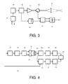
- FIGS. 3 and 4 represent the block diagram of a lidar according to the invention
- FIGS. 5, 6 and 7 represent the measurement signals in three different cases, the first without frequency realignment, the second by shifting the frequency by a positive value and the third by shifting the frequency by a negative value.
- FIGS. 3 and 4 represent the block diagram of a lidar according to the invention.
- FIG. 3 represents the transmission and reception assemblies of the lidar.
- FIG. 4 represents an example of processing of the electrical signal obtained from the reception assembly.
- the transmission assembly comprises a laser source 40 modulated by a frequency modulation assembly 41 , the function of which is detailed below.
- the transmission beam passes through an optical splitter 42 .
- a first part is amplified by the amplifier 43 , passes through the circulator 44 and then is focused in the atmosphere using a transmission-reception telescope 45 at the distance D from the lidar.
- a second part passes through a delay line 46 of optical length equal to twice the distance and is directed to the first port of an interferometer 47 .
- the backscattered wave passes through the telescope 45 , the circulator 44 and is directed to the second port of the interferometer 47 .
- the beat of the two optical waves injected into the interferometer produces the electrical signal at the output of the photodetector 48 .
- ⁇ laser ( t ) ⁇ 0 +A ⁇ sin(2 ⁇ ft )
- the transmission laser source can transmit in the near infrared.
- the frequency ⁇ 0 is then 1.94 ⁇ 10 14 Hz and corresponds to a wavelength ⁇ of 1.55 ⁇ m.
- the amplitude A lies between 10 MHz and100 MHz and, more specifically, can be 50 MHz.
- the frequency f lies between 2 kHz and 20 kHz and, more specifically, can be 10 kHz.
- V backscatter ⁇ ( t ) V laser ⁇ ( t - 2 ⁇ D c ) + f Doppler
- the frequency f Doppler corresponds to the frequency Doppler shift which is:
- V being the speed of the target along the axis of the transmission laser beam.
- the Doppler shift frequency is 1.3 MHz for a speed of 1 m/s.
- the lidar according to the invention comprises an interferometer 47 capable of ensuring a heterodyne detection, that is to say of producing an electrical signal proportional to the beat between the transmission optical wave and the backscattered optical wave.
- the frequency of this beat signal f beat is therefore, at the instant t:
- f beat ⁇ ( t ) ⁇ 2 ⁇ A ⁇ sin ⁇ ( - 2 ⁇ ⁇ ⁇ ⁇ fD c ) ⁇ cos ⁇ ( 2 ⁇ ⁇ ⁇ ⁇ f ⁇ ( t - D c ) ) + f Doppler ⁇
- the instantaneous frequency of the beat signal is therefore the sum of the Doppler frequency and of a modulation term.
- This term is modulated sinusoidally with the same modulation frequency as the transmission wave and has an amplitude modified by a factor
- the total amplitude of the variations of the frequency of the beat signal is therefore 2.08 MHz with the preceding numerical values.
- the determination of the beat frequency is done conventionally by spectral or Fourier analysis.
- the beat frequency is strictly equal to the absolute value of the Doppler frequency and it is impossible to get back to the sign of the speed of the target relative to the lidar.
- the principle consists in conducting two computations. In the first computation, the instantaneous spectrum of the received signal is realigned by adding the modulation term to the measured frequency. In the second computation, the opposite of this realignment term is added. These realignment terms are denoted f realign+ and f realign ⁇ . Their expressions are as follows:
- the two spectra obtained are therefore identical but shifted relative to one another in frequency.
- the frequency signal resulting from the beat is generally embedded in the noise for an individual spectrum. It is therefore necessary to perform a non-coherent integration over several tens of milliseconds to make it emerge from the noise. Since this integration time is long relative to the modulation of the signal, the result thereof is a spectral spreading of the ray of the signal over approximately 2 MHz. This spectral spreading is to be compared with the Doppler shift which is 1.3 MHz for a speed of 1 m/s with the same numerical data.
- FIG. 4 represents a possible implementation of the heterodyne signal processing assembly according to the invention. This processing comprises two stages. A first stage for measuring the reception heterodyne signal comprising the following means:
- the size of the Fourier transform has to be chosen to be long enough to obtain a frequency discretization pitch of approximately one tenth of the amplitude of the expected frequency modulation.
- the Gaussian width weighting window at 1/e 2 is equal to 1 ⁇ s and the Fourier transform comprises 4096 points with a sampling frequency of approximately 400 MHz.
- the frequency discretization pitch is therefore of the order of 100 kHz.
- a second stage for processing the spectra obtained from the first stage comprising the following means:
- a synchronization signal 60 makes it possible to synchronize the processing chains with the frequency modulation assembly 41 .
- FIGS. 5, 6 and 7 represent the spectra of the measurement signals in three different cases, the first represented in FIG. 5 without frequency realignment, the second represented in FIG. 6 with the frequency shifted by a positive value and the third represented in FIG. 7 with the frequency shifted by a negative value.
- the positive realignment value corresponds to the assumption of a positive speed and the negative realignment value corresponds to the assumption of a negative speed.
- the x axis corresponds to the frequencies expressed in megahertz and the y axis corresponds to the amplitudes of the spectra expressed in decibels.
- the speed of the target is approximately 23 m/s, which corresponds to a Doppler frequency of 30 MHz, the distance D to the target is 25 m, the frequency A is 50 MHz and the modulation frequency f is 10 kHz.
- the spectra obtained exhibit a significant ray at the same Doppler frequency of 30 MHz.
- the amplitude I MAX of the rays is different. It is maximum when the realignment frequency has the same sign as the Doppler frequency. Such is the case in FIG. 7 .
- the speed of the target is therefore negative in this example.
- a simple processing is thus obtained that makes it possible to determine the direction and the value of the speed of the target relative to the lidar.
- the computation of the realignment can also be performed in a single step. Indeed, since the heterodyne signal is real, its Fourier transform exhibits a Hermitian symmetry and the square of the modulus of this Fourier transform is even.
- the two realignments can therefore be performed in a single step by shifting the signed frequency spectrum of the received signal by the previously computed realignment term. This in effect corresponds to adding the realignment term for the positive frequencies and subtracting it as an absolute value for the negative frequencies.
- This computation method also offers a second advantage.
- the act of shifting the spectrum corresponds mathematically to convoluting it by a Dirac distribution at the desired frequency.
- Such a convolution in the frequency domain corresponds to a multiplication by a complex exponential function in the time domain. It is therefore possible to produce the realignment of the spectrum in terms of signed frequencies for any value of the realignment by multiplying the heterodyne signal measured by a numerical complex exponential function at said realignment frequency before performing the Fourier transformation. All of the processing operations are then performed on the signed spectra. In the aggregated spectra, the ray corresponding to the incorrect sign of the speed exhibits a notable spectral spread which makes it possible to unambiguously choose the ray corresponding to the correct speed sign.
Landscapes
- Physics & Mathematics (AREA)
- Engineering & Computer Science (AREA)
- Electromagnetism (AREA)
- Computer Networks & Wireless Communication (AREA)
- General Physics & Mathematics (AREA)
- Signal Processing (AREA)
- Radar, Positioning & Navigation (AREA)
- Remote Sensing (AREA)
- Multimedia (AREA)
- Aviation & Aerospace Engineering (AREA)
- Optics & Photonics (AREA)
- Optical Radar Systems And Details Thereof (AREA)
Abstract
Description
-
- Reliability: the acousto-optic modulator is a fragile component, notably in a severe thermal and vibratory environment and is not therefore suited to the aeronautical environment;
- Cost: the cost of the acousto-optic modulator is high relative to the cost of the optical architecture as a whole;
- Increased frequency range. For a symmetrical speed range, the Doppler frequency range to be analyzed is doubled, the computation power needed at the processing level is commensurately increased.
V=f D·λ/2
If the speed is positive, then the Doppler shift is +5 MHz, the frequency f+ is 4 MHz and the frequency f− is 6 MHz. Conversely, if the speed is negative, then the Doppler shift is −5 MHz, the frequency f+ is 6 MHz and the frequency f− is 4 MHz. Thus, it is possible to retrieve, by comparing the difference between the frequencies f+ and f−, not only the value of the speed, but its sign. The difference between the two frequencies is representative of the distance to the object.
-
- An analogue-digital converter;
- An observation window of determined duration limiting the duration of the digital heterodyne signal;
- Means making it possible to perform the Fourier transform of the digital heterodyne signal and compute the square of its modulus to obtain its spectrum;
-
- Two analysis chains arranged in parallel, each chain ensuring the functions of realignment of the spectrum by a positive or negative frequency value, of accumulation of a determined quantity of digital signals and of estimation of the Doppler frequency and of the amplitude of the peak corresponding to said Doppler frequency;
- Means for computing the value of the speed of the target and direction relative to the lidar.
-
- Of accumulation of a determined quantity of signed digital spectra and of estimation of the Doppler frequency,
- Of analysis of the amplitude and of the width of the peak corresponding to said Doppler frequency;
- Of computation of the value of the speed of the target and direction relative to the lidar as a function of said Doppler frequency and of the amplitude and the width of the corresponding peak.
νlaser(t)=ν0 +A·sin(2πft)
-
- A being the amplitude of the frequency modulation
- F being the modulation frequency
This factor is low and, taking the preceding numerical values, that is to say the frequency f equal to 10 kHz, D equal to 25 m and A equal to 50 MHz, the following is obtained:
-
- An analogue-
digital converter 50 for the electronic signal from thephotodetector 48; - An
observation window 51 of determined duration limiting the duration of the digital heterodyne signal; - A means 52 making it possible to perform the complex Fourier transform of the heterodyne signal;
- Means 53, 54 and 55 making it possible to perform the computation of the squares of the real and imaginary parts of the Fourier transform of the digital heterodyne signal, and then sum them.
- An analogue-
-
- Two analysis chains arranged in parallel, each chain ensuring the functions of
addition 56 + or ofsubtraction 56 − of a spectrum frequency realignment term, ofaccumulation 57 of a determined quantity of digital spectra, of detection and ofestimation 58 of the Doppler frequency and of the amplitude of the peak corresponding to said Doppler frequency; - Means 59 for computing the value of the speed of the target and its direction relative to the lidar.
- Two analysis chains arranged in parallel, each chain ensuring the functions of
Claims (7)
Applications Claiming Priority (2)
| Application Number | Priority Date | Filing Date | Title |
|---|---|---|---|
| FR1401344A FR3022349B1 (en) | 2014-06-13 | 2014-06-13 | LIDAR DOPPLER WITH RELATIVE MEASUREMENT OF SPEED |
| FR1401344 | 2014-06-13 |
Publications (2)
| Publication Number | Publication Date |
|---|---|
| US20160170023A1 US20160170023A1 (en) | 2016-06-16 |
| US9778362B2 true US9778362B2 (en) | 2017-10-03 |
Family
ID=51894084
Family Applications (1)
| Application Number | Title | Priority Date | Filing Date |
|---|---|---|---|
| US14/734,989 Expired - Fee Related US9778362B2 (en) | 2014-06-13 | 2015-06-09 | Relative speed measuring doppler LiDAR |
Country Status (3)
| Country | Link |
|---|---|
| US (1) | US9778362B2 (en) |
| EP (1) | EP2955542B1 (en) |
| FR (1) | FR3022349B1 (en) |
Cited By (14)
| Publication number | Priority date | Publication date | Assignee | Title |
|---|---|---|---|---|
| US20170307648A1 (en) * | 2014-12-12 | 2017-10-26 | Mitsubishi Electric Corporation | Laser radar device |
| US20190293794A1 (en) * | 2018-03-26 | 2019-09-26 | Huawei Technologies Co., Ltd. | Coherent lidar method and apparatus |
| US10838061B1 (en) * | 2019-07-16 | 2020-11-17 | Blackmore Sensors & Analytics, LLC. | Method and system for enhanced velocity resolution and signal to noise ratio in optical phase-encoded range detection |
| US11550036B2 (en) | 2016-01-31 | 2023-01-10 | Velodyne Lidar Usa, Inc. | Multiple pulse, LIDAR based 3-D imaging |
| US11561305B2 (en) | 2016-06-01 | 2023-01-24 | Velodyne Lidar Usa, Inc. | Multiple pixel scanning LIDAR |
| US11703569B2 (en) | 2017-05-08 | 2023-07-18 | Velodyne Lidar Usa, Inc. | LIDAR data acquisition and control |
| US11796648B2 (en) | 2018-09-18 | 2023-10-24 | Velodyne Lidar Usa, Inc. | Multi-channel lidar illumination driver |
| US11808891B2 (en) | 2017-03-31 | 2023-11-07 | Velodyne Lidar Usa, Inc. | Integrated LIDAR illumination power control |
| US11885958B2 (en) | 2019-01-07 | 2024-01-30 | Velodyne Lidar Usa, Inc. | Systems and methods for a dual axis resonant scanning mirror |
| US11933967B2 (en) | 2019-08-22 | 2024-03-19 | Red Creamery, LLC | Distally actuated scanning mirror |
| US11971507B2 (en) | 2018-08-24 | 2024-04-30 | Velodyne Lidar Usa, Inc. | Systems and methods for mitigating optical crosstalk in a light ranging and detection system |
| US12123950B2 (en) | 2016-02-15 | 2024-10-22 | Red Creamery, LLC | Hybrid LADAR with co-planar scanning and imaging field-of-view |
| US12399279B1 (en) | 2016-02-15 | 2025-08-26 | Red Creamery Llc | Enhanced hybrid LIDAR with high-speed scanning |
| US12399278B1 (en) | 2016-02-15 | 2025-08-26 | Red Creamery Llc | Hybrid LIDAR with optically enhanced scanned laser |
Families Citing this family (21)
| Publication number | Priority date | Publication date | Assignee | Title |
|---|---|---|---|---|
| FR3022349B1 (en) * | 2014-06-13 | 2016-09-23 | Thales Sa | LIDAR DOPPLER WITH RELATIVE MEASUREMENT OF SPEED |
| CN109073755A (en) * | 2016-01-27 | 2018-12-21 | 三菱电机株式会社 | coherent laser radar device |
| GB201607875D0 (en) | 2016-05-05 | 2016-06-22 | Qinetiq Ltd | Phase noise compensation system, and method |
| DE102017106226A1 (en) * | 2017-03-22 | 2018-09-27 | Metek Meteorologische Messtechnik Gmbh | LIDAR measuring device |
| CN108415031B (en) * | 2018-01-15 | 2020-08-28 | 北京航空航天大学 | Hyperspectral full-waveform laser radar system based on spectral splitting |
| US11536805B2 (en) | 2018-06-25 | 2022-12-27 | Silc Technologies, Inc. | Optical switching for tuning direction of LIDAR output signals |
| US12535586B2 (en) | 2018-08-31 | 2026-01-27 | SiLC Technology, Inc. | Reduction of ADC sampling rates in LIDAR systems |
| US12429569B2 (en) | 2019-05-17 | 2025-09-30 | Silc Technologies, Inc. | Identification of materials illuminated by LIDAR systems |
| US11650317B2 (en) | 2019-06-28 | 2023-05-16 | Silc Technologies, Inc. | Use of frequency offsets in generation of LIDAR data |
| CN111273307A (en) * | 2020-01-17 | 2020-06-12 | 中国科学院上海技术物理研究所 | High-precision chirped laser coherent fusion ranging method based on Kalman filter algorithm |
| FR3110002B1 (en) * | 2020-05-06 | 2022-04-22 | Office National D’ Etudes Et De Rech Aerospatiales | DETECTION AND TELEMETRY BY PULSES OF ELECTROMAGNETIC RADIATION |
| US12449538B2 (en) * | 2020-05-26 | 2025-10-21 | United States Of America As Represented By The Administrator Of Nasa | Ambiguity mitigation for FMCW lidar system |
| US12306344B1 (en) * | 2020-08-25 | 2025-05-20 | Silc Technologies, Inc. | Reduction of components in LIDAR systems |
| US12541009B2 (en) | 2021-06-17 | 2026-02-03 | Silc Technologies, Inc. | Scanning multiple LIDAR system output signals |
| US12411213B2 (en) | 2021-10-11 | 2025-09-09 | Silc Technologies, Inc. | Separation of light signals in a LIDAR system |
| US12553995B2 (en) | 2022-02-14 | 2026-02-17 | Silc Technologies, Inc. | Data refinement in optical systems |
| US12578443B2 (en) | 2022-04-23 | 2026-03-17 | Silc Technologies, Inc. | Data refinement in optical imaging systems |
| US12422618B2 (en) | 2022-10-13 | 2025-09-23 | Silc Technologies, Inc. | Buried taper with reflecting surface |
| US20240151848A1 (en) * | 2022-11-09 | 2024-05-09 | The Boeing Company | Laser vehicle speed detection system |
| US12578439B2 (en) | 2023-04-11 | 2026-03-17 | Silc Technologies, Inc. | Increasing resolution in imaging systems |
| CN117411546B (en) * | 2023-12-11 | 2024-02-09 | 南昌大学 | LED communication capability evaluation method and system |
Citations (7)
| Publication number | Priority date | Publication date | Assignee | Title |
|---|---|---|---|---|
| US2738502A (en) * | 1947-12-30 | 1956-03-13 | Esther M Armstrong | Radio detection and ranging systems |
| US6608669B2 (en) | 2000-09-22 | 2003-08-19 | Virginia Tech Intellectual Properties | Quadrature processed LIDAR system |
| US6621561B2 (en) | 2000-09-22 | 2003-09-16 | Virginia Tech Intellectual Properties | Doppler rotational velocity sensor |
| US20050083513A1 (en) | 2002-12-20 | 2005-04-21 | Rogers Philip L. | Quadrature processed lidar system |
| FR2870004A1 (en) | 2004-05-04 | 2005-11-11 | Thales Sa | MEASURING DEVICE WITH LOW COST OF FREQUENCY SHIFTING BY DOPPLER EFFECT |
| FR2965064A1 (en) | 2010-09-22 | 2012-03-23 | Onera (Off Nat Aerospatiale) | TELEMETRIC MEASUREMENT USING A HETERODYNE DETECTION LIDAR TYPE DEVICE |
| EP2955542A1 (en) * | 2014-06-13 | 2015-12-16 | Thales | Doppler lidar with relative speed measurement |
-
2014
- 2014-06-13 FR FR1401344A patent/FR3022349B1/en active Active
-
2015
- 2015-06-08 EP EP15171034.0A patent/EP2955542B1/en active Active
- 2015-06-09 US US14/734,989 patent/US9778362B2/en not_active Expired - Fee Related
Patent Citations (9)
| Publication number | Priority date | Publication date | Assignee | Title |
|---|---|---|---|---|
| US2738502A (en) * | 1947-12-30 | 1956-03-13 | Esther M Armstrong | Radio detection and ranging systems |
| US6608669B2 (en) | 2000-09-22 | 2003-08-19 | Virginia Tech Intellectual Properties | Quadrature processed LIDAR system |
| US6621561B2 (en) | 2000-09-22 | 2003-09-16 | Virginia Tech Intellectual Properties | Doppler rotational velocity sensor |
| US20050083513A1 (en) | 2002-12-20 | 2005-04-21 | Rogers Philip L. | Quadrature processed lidar system |
| FR2870004A1 (en) | 2004-05-04 | 2005-11-11 | Thales Sa | MEASURING DEVICE WITH LOW COST OF FREQUENCY SHIFTING BY DOPPLER EFFECT |
| FR2965064A1 (en) | 2010-09-22 | 2012-03-23 | Onera (Off Nat Aerospatiale) | TELEMETRIC MEASUREMENT USING A HETERODYNE DETECTION LIDAR TYPE DEVICE |
| EP2955542A1 (en) * | 2014-06-13 | 2015-12-16 | Thales | Doppler lidar with relative speed measurement |
| FR3022349A1 (en) * | 2014-06-13 | 2015-12-18 | Thales Sa | LIDAR DOPPLER WITH RELATIVE MEASUREMENT OF SPEED |
| US20160170023A1 (en) * | 2014-06-13 | 2016-06-16 | Thales | Relative speed measuring doppler lidar |
Non-Patent Citations (1)
| Title |
|---|
| Search Report issued in French application No. 1401344, dated Mar. 9, 2015 (8 pages). |
Cited By (17)
| Publication number | Priority date | Publication date | Assignee | Title |
|---|---|---|---|---|
| US20170307648A1 (en) * | 2014-12-12 | 2017-10-26 | Mitsubishi Electric Corporation | Laser radar device |
| US11550036B2 (en) | 2016-01-31 | 2023-01-10 | Velodyne Lidar Usa, Inc. | Multiple pulse, LIDAR based 3-D imaging |
| US12399278B1 (en) | 2016-02-15 | 2025-08-26 | Red Creamery Llc | Hybrid LIDAR with optically enhanced scanned laser |
| US12399279B1 (en) | 2016-02-15 | 2025-08-26 | Red Creamery Llc | Enhanced hybrid LIDAR with high-speed scanning |
| US12123950B2 (en) | 2016-02-15 | 2024-10-22 | Red Creamery, LLC | Hybrid LADAR with co-planar scanning and imaging field-of-view |
| US11561305B2 (en) | 2016-06-01 | 2023-01-24 | Velodyne Lidar Usa, Inc. | Multiple pixel scanning LIDAR |
| US11808891B2 (en) | 2017-03-31 | 2023-11-07 | Velodyne Lidar Usa, Inc. | Integrated LIDAR illumination power control |
| US11703569B2 (en) | 2017-05-08 | 2023-07-18 | Velodyne Lidar Usa, Inc. | LIDAR data acquisition and control |
| US20190293794A1 (en) * | 2018-03-26 | 2019-09-26 | Huawei Technologies Co., Ltd. | Coherent lidar method and apparatus |
| US10901089B2 (en) * | 2018-03-26 | 2021-01-26 | Huawei Technologies Co., Ltd. | Coherent LIDAR method and apparatus |
| US11971507B2 (en) | 2018-08-24 | 2024-04-30 | Velodyne Lidar Usa, Inc. | Systems and methods for mitigating optical crosstalk in a light ranging and detection system |
| US11796648B2 (en) | 2018-09-18 | 2023-10-24 | Velodyne Lidar Usa, Inc. | Multi-channel lidar illumination driver |
| US11885958B2 (en) | 2019-01-07 | 2024-01-30 | Velodyne Lidar Usa, Inc. | Systems and methods for a dual axis resonant scanning mirror |
| US12241978B2 (en) | 2019-07-16 | 2025-03-04 | Aurora Operations, Inc. | Method and system for enhanced velocity resolution and signal to noise ratio in optical phase-encoded range detection |
| US11709267B2 (en) | 2019-07-16 | 2023-07-25 | Blackmore Sensors & Analytics, Llc | Method and system for enhanced velocity resolution and signal to noise ratio in optical phase-encoded range detection |
| US10838061B1 (en) * | 2019-07-16 | 2020-11-17 | Blackmore Sensors & Analytics, LLC. | Method and system for enhanced velocity resolution and signal to noise ratio in optical phase-encoded range detection |
| US11933967B2 (en) | 2019-08-22 | 2024-03-19 | Red Creamery, LLC | Distally actuated scanning mirror |
Also Published As
| Publication number | Publication date |
|---|---|
| EP2955542B1 (en) | 2017-04-26 |
| US20160170023A1 (en) | 2016-06-16 |
| EP2955542A1 (en) | 2015-12-16 |
| FR3022349A1 (en) | 2015-12-18 |
| FR3022349B1 (en) | 2016-09-23 |
Similar Documents
| Publication | Publication Date | Title |
|---|---|---|
| US9778362B2 (en) | Relative speed measuring doppler LiDAR | |
| US11125879B2 (en) | Method for processing a signal arising from coherent lidar and associated lidar system | |
| JP7169642B2 (en) | Optical measuring device and measuring method | |
| EP3436845B1 (en) | Direct detection lidar system and method with frequency modulation (fm) transmitter and quadrature receiver | |
| JP6157735B2 (en) | Laser radar equipment | |
| JP6935506B2 (en) | How to process signals from coherent riders to reduce noise and related rider systems | |
| US20210382164A1 (en) | Multi-tone continuous wave detection and ranging | |
| EP2866050B1 (en) | Wind measurement coherent lidar device | |
| US12535566B2 (en) | Optical measurement device and measurement method | |
| US11112502B2 (en) | Laser radar system | |
| US11630189B2 (en) | Multi-tone continuous wave detection and ranging | |
| CN113253301B (en) | Multi-frequency pulsed lidar signal processing method and wind measurement radar system | |
| CN104243067A (en) | Doppler frequency shift detection method and device based on photonic technology | |
| US20230131584A1 (en) | Multi-tone continuous wave detection and ranging | |
| CN112262324B (en) | Operating method, control unit, laser radar system and device for laser radar system | |
| RU2602274C1 (en) | Radar method and device for remote measurement of full velocity vector of meteorological object | |
| WO2021024759A1 (en) | Remote airstream observation device, remote airstream observation method, and program | |
| US12313792B2 (en) | Frequency-modulated coherent lidar | |
| RU2545498C1 (en) | Method to detect speed and direction of wind and incoherent doppler lidar | |
| Grubb | Signal Processing Algorithms for Doppler LiDAR Sensors |
Legal Events
| Date | Code | Title | Description |
|---|---|---|---|
| AS | Assignment |
Owner name: THALES, FRANCE Free format text: ASSIGNMENT OF ASSIGNORS INTEREST;ASSIGNORS:RONDEAU, PHILIPPE;SCHLOTTERBECK, JEAN-PIERRE;LACONDEMINE, XAVIER;SIGNING DATES FROM 20150924 TO 20150929;REEL/FRAME:036741/0113 |
|
| STCF | Information on status: patent grant |
Free format text: PATENTED CASE |
|
| MAFP | Maintenance fee payment |
Free format text: PAYMENT OF MAINTENANCE FEE, 4TH YEAR, LARGE ENTITY (ORIGINAL EVENT CODE: M1551); ENTITY STATUS OF PATENT OWNER: LARGE ENTITY Year of fee payment: 4 |
|
| FEPP | Fee payment procedure |
Free format text: MAINTENANCE FEE REMINDER MAILED (ORIGINAL EVENT CODE: REM.); ENTITY STATUS OF PATENT OWNER: LARGE ENTITY |
|
| LAPS | Lapse for failure to pay maintenance fees |
Free format text: PATENT EXPIRED FOR FAILURE TO PAY MAINTENANCE FEES (ORIGINAL EVENT CODE: EXP.); ENTITY STATUS OF PATENT OWNER: LARGE ENTITY |
|
| STCH | Information on status: patent discontinuation |
Free format text: PATENT EXPIRED DUE TO NONPAYMENT OF MAINTENANCE FEES UNDER 37 CFR 1.362 |
|
| FP | Lapsed due to failure to pay maintenance fee |
Effective date: 20251003 |