CROSS-REFERENCE TO RELATED APPLICATIONS
This application is a continuation-in-part of U.S. patent application Ser. No. 14/477,991, filed on Sep. 5, 2014, which claims the benefit of U.S. Provisional Patent Application Ser. No. 61/880,394, filed Sep. 20, 2013. This application claims the benefit of U.S. Provisional Patent Application Ser. No. 62/087,767, filed Dec. 4, 2014. The entire disclosures of all of the above applications are hereby incorporated by reference herein as though fully set forth in their entireties.
TECHNICAL FIELD
The present disclosure generally relates to track adjusters that may be used, for example, in connection with vehicle seats.
BACKGROUND
Easy entry seat assemblies can be used in vehicles that have multiple rows of seats to provide easy entry to a rear row of seats in the vehicle. For example, a typical easy entry seat assembly may have a backrest that is pivotally supported relative to a seat bottom for movement between an upright seated position, a forward easy entry position, or a fold flat position. A typical easy entry assembly may allow the seat bottom to move forward beyond a comfort range of seating positions.
SUMMARY
In embodiments, a seat adjuster may comprise an end stop bracket configured for connection with a fixed track, an easy entry lever, a comfort lever activator configured for connection or engagement with a lockset, a cross member bracket that may be configured for connection with a movable track and configured to rotatably support a cross member, and/or a cross member cable that may connect the comfort lever activator to said cross member such that rotation of said cross member may cause the comfort lever activator to rotate and to connect with and/or engage said lockset. In embodiments, the easy entry lever may be configured to rotate between a first position in which the easy entry lever may connect with and/or engage the end stop bracket and may prevent movement of a seat from a comfort range into an easy entry range, and a second position in which the easy entry lever may not impede or prevent movement of the seat from the comfort range into the easy entry range.
In embodiments, a vehicle seat adjuster may comprise a first fixed track, a second fixed track, a first movable track that may be coupled to slide relative to the first fixed track, a second movable track that may be coupled to slide relative to the second fixed track, an end stop bracket that may be connected to the first fixed track, an easy entry lever that may be connected to the first movable track, a cross member, and/or a comfort lever activator that may be connected to the first movable track and may be configured for connection and/or engagement with a lockset. In embodiments, a vehicle seat adjuster may include a first cross member bracket that may be connected to the first movable track and may be configured to rotatably support a first end of the cross member. In embodiments, a vehicle seat adjuster may include a second cross member bracket that may be connected to the second movable track and may be configured to rotatably support a second end of the cross member. In embodiments, a vehicle seat adjuster may include a cross member cable that may connect the comfort lever activator to said cross member such that rotation of said cross member causes the comfort lever activator to rotate and to connect with and/or engage said lockset. In embodiments, the easy entry lever may be configured to rotate between a first position in which the easy entry lever may engage the end stop bracket and impede or prevent movement of the first movable track from a comfort range into an easy entry range, and a second position in which the easy entry lever may not prevent movement of the first movable track from the comfort range into the easy entry range.
Various aspects of the present disclosure will become apparent to those skilled in the art from the following detailed description of the various embodiments, when read in light of the accompanying drawings.
BRIEF DESCRIPTION OF THE DRAWINGS
FIGS. 1A and 1B are perspective views generally illustrating portions of vehicle seat adjuster, in accordance with embodiments of the present disclosure.
FIG. 1C is a bottom view generally illustrating portions of a vehicle seat adjuster, in accordance with embodiments of the present disclosure.
FIG. 2 is an enlarged perspective view generally illustrating portions of a vehicle seat adjuster, in accordance with embodiments of the present disclosure.
FIG. 3A is an enlarged perspective view generally illustrating portions of a vehicle seat adjuster, in accordance with embodiments of the present disclosure
FIG. 3B is a perspective view of a base bracket, in accordance with embodiments of the present disclosure.
FIGS. 3C and 3D are perspective views generally illustrating portions of easy entry levers and easy entry lever activators, in accordance with embodiments of the present disclosure.
FIGS. 4A and 4B are perspective views generally illustrating portions of a vehicle seat adjuster, in accordance with embodiments of the present disclosure.
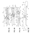
FIGS. 5A, 5B, and 5C are side views generally illustrating portions of a vehicle seat adjuster, in accordance with embodiments of the present disclosure.
FIG. 5D is a perspective view generally illustrating portions of a vehicle seat adjuster, in accordance with embodiments of the present disclosure.
FIGS. 6A and 6B are perspective views generally illustrating portions of end stop brackets of a vehicle seat adjuster, in accordance with embodiments of the present disclosure.
FIG. 7 is a perspective view generally illustrating portions of a vehicle seat adjuster, in accordance with embodiments of the present disclosure.
FIG. 8 is a perspective view generally illustrating portions of a vehicle seat adjuster, in accordance with embodiments of the present disclosure.
FIG. 9 is a top view generally illustrating portions of a vehicle seat adjuster, in accordance with embodiments of the present disclosure.
FIGS. 10 and 11 are perspective views generally illustrating portions of a vehicle seat adjuster, in accordance with embodiments of the present disclosure.
FIG. 12 is a bottom view generally illustrating portions of a vehicle seat adjuster, in accordance with embodiments of the present disclosure.
FIGS. 13-20 are perspective views generally illustrating portions of a vehicle seat adjuster, in accordance with embodiments of the present disclosure.
DETAILED DESCRIPTION
Referring now to the drawings, there is generally illustrated in FIGS. 1A and 1B a vehicle seat portion 10 including a track adjuster, indicated generally at 12, in accordance with an embodiment of the present disclosure. In embodiments, vehicle seat portion 10 may include a seat cushion 10 a, a seatback 10 b, and/or a seat frame 10 c. In embodiments, vehicle seat adjuster 12 may permit vehicle seat portion 10 to be adjusted by a user in a longitudinal direction L. Vehicle seat adjuster 12 may include easy entry (EE) functionality, which may facilitate ingress and/or egress of a vehicle occupant and/or cargo. It should be appreciated, however, that vehicle seat adjuster 12 can be used in any appropriate environment and for any desired purpose, which may or may not be in connection with a vehicle and/or a seat.
In embodiments, vehicle seat adjuster 12 may include one or more first seat tracks 14, 14′ and/or one or more second seat tracks 16, 16′. Second seat tracks 16, 16′ may be connected and/or fixed to a base and/or floor, such as of a vehicle. First tracks 14, 14′ may be operatively coupled to second tracks 16, 16′, respectively, to slide along second tracks 16, 16′ (e.g., first tracks 14, 14′ may comprise movable tracks). One or more locking devices 20, 20′ may be connected to first tracks 14, 14′ and/or second tracks 16, 16′. Locking device 20 may be configured to restrict relative movement between first and second tracks 14, 16 and/or locking device 20′ may be configured to restrict relative movement between first and second tracks 14′, 16′.
In embodiments, such as generally illustrated in FIGS. 1A-1C and 2, seat adjuster 12 may include a locking device (e.g., locking device 20 and/or 20′), a cross member 22, a handle 24, an easy entry lever activator (EE lever activator) 26, an adjustable end stop lever (EE lever) 28, a comfort lever activator 30, an easy entry base bracket (EE base bracket) 32, and/or an end stop bracket 50. In embodiments, cross member 22 may include a cross tube. EE base bracket 32 may be fixed to first track 14 and may support cross member 22, EE lever activator 26, EE lever 28, and/or comfort lever activator 30. Comfort lever activator 30 may be referred to herein as activation lever 30.
As generally illustrated in FIGS. 3A and 3B, for example and without limitation, EE base bracket 32 may be generally L-shaped and may include a generally horizontal portion 32 a which may be fixed to a top portion 14 b of first track 14 and/or EE base bracket 32 may include a generally vertical portion 32 b that may extend downwardly from a side of horizontal portion 32 a. In embodiments, EE lever 28 may be rotatably fixed to generally vertical portion 32 b, which may include EE lever 28 being configured to rotate relative to vertical portion 32 b, and EE lever 28 not being configured to translate to a substantial degree relative to vertical portion 32 b. For example, and without limitation, generally vertical portion 32 b may include a connecting portion 32 c, which may include an aperture 32 d configured to receive a connecting member 40 and/or a bushing 34 a.
In embodiments, generally horizontal portion 32 a may include an aperture 32 e configured to receive at least a portion of a lock plate actuator 62 of lockset 60. Generally horizontal portion 32 a may, additionally or alternatively, include one or more apertures 32 f that may be configured to connect seat frame 10 c to EE base bracket 32. In embodiments, seat frame 10 c may be connected to EE base bracket 32 via one or more connecting members 10 d, which may include studs. EE base bracket 32 may include an angled portion 32 g, which may include a recess 32 h. Angled portion 32 g may be configured to be connected to a connection member 80. For example, and without limitation, connection member 80 may comprise a cable that may include a sheath 82, and angled portion 32 g and/or recess 32 h may be configured to hold/retain sheath 82. In embodiments, angled portion 32 g and/or recess 32 h may function as a cable retainer. In embodiments, connection member 80 may be referred to herein as easy entry cable 80, but is not limited to a cable.
As generally illustrated in FIGS. 3A-3D, connecting member 40 may be configured to connect EE base bracket 32 and EE lever 28. Connecting member 40 may take a variety of forms, and may include, without limitation, a body portion 40 a and/or a head portion 40 b. Connecting member 40 may be generally cylindrical and/or head portion 40 b may have a greater diameter than body portion 40 a. For example, and without limitation, connecting member 40 may include a rivet. Connecting member 40 may be configured to be connected to a retaining member 42. Retaining member 42 may include, for example, a star lock washer that may be configured to retain connecting member 40 in EE base bracket aperture 32 d.
In embodiments, EE lever 28 may be supported by EE base bracket 32 via connecting member 40. For example, and without limitation, EE lever 28 may include an aperture 28 a that may be configured to receive at least a portion of connecting member 40. Bushing 34 a may be arranged on connecting member 40 and/or may be arranged between EE lever 28 and connecting member 40 to facilitate rotational movement of EE lever 28 relative to EE base bracket 32.
In embodiments, EE lever 28 may be configured to rotatably support cross member 22. For example, and without limitation, EE lever 28 may include a cross member connecting portion 28 b. Cross member connecting portion 28 b may include an aperture 28 c that may be configured to receive at least a portion of cross member 22 and/or cross member 22 may be rotatably supported in aperture 28 c of EE lever 28. Cross member connecting portion 28 b may be connected to and/or configured to receive a bushing 34 b that may be configured to receive at least a portion of cross member 22, and/or at least a portion of cross member 22 may extend into aperture 28 c. Bushing 34 b may be configured to facilitate relative movement between cross member 22 and EE lever 28. For example, and without limitation, bushing 34 b may be arranged in cross member connecting portion 28 b and a portion of cross member 22 may be inserted into bushing 34 b such that cross member 22 may be able to rotate within bushing 34 b and/or bushing 34 b may be configured not to rotate relative to EE lever 28. In embodiments, cross member 22 may be configured to rotate independently of EE lever 28 in at least some positions of EE lever 28. For example, and without limitation, cross member 22 may be rotated by handle 24 without rotation of EE lever 28, which may allow for first tracks 14, 14′ to move within comfort range 18 a, but may not allow first tracks 14, 14′ to move into EE range 18 b (see, e.g., FIG. 5A). In embodiments, cross member 22 and EE lever 28, which may include EE lever activator 26, cross member connecting portion 28 b, EE lever protrusion 28 d, and/or flexible member 28 g, may be configured to rotate about axes that are parallel and/or coincident to each other.
In embodiments, EE lever 28 may include a cross member actuator 28 f. Cross member actuator 28 f may be configured to cause cross member 22 to rotate in at least one direction, which may include cross member actuator 28 f contacting comfort lever activator 30. For example, and without limitation, cross member actuator 28 f may be configured to transfer rotational movement of EE lever 28 to cross member 22 via contact with comfort lever activator 30, which may be fixed to cross member 22. A flexible member 28 g may be arranged between cross member actuator 28 f and comfort lever activator 30 and may prevent actual contact and/or may absorb forces corresponding to contact between cross member actuator 28 f and comfort lever activator 30.
In embodiments, EE lever 28 may be generally u-shaped, which may include EE lever activator 26 and/or EE lever protrusion 28 d on one side, and cross member connecting portion 28 b, cross member actuator 28 f, and/or flexible member 28 g at the other side. In embodiments, portions and/or all of bushing 34 b and/or connecting member 40 may be disposed between the two sides. In embodiments, EE lever 28 may be formed as a single unitary element, and may include, for example, EE lever activator 26, EE lever protrusion 28 d, EE lever angled portion 28 e, cross member actuator 28 f, flexible member 28 g, and/or movement restricting element 28 h.
As generally illustrated in FIGS. 4A and 4B, a locking device (e.g., locking device 20, and/or locking device 20′) may include a lockset 60 that may be arranged between first and second tracks (e.g., tracks 14, 16 and/or track 14′, 16′). For example, and without limitation, lockset 60 may be configured to selectively engage engagement portions 16 a of second track 16. Lockset 60 may include a lock plate actuator 62, a lock plate actuator spring 64, one or more lock plates 66, and/or one or more lock plate springs 68.
In embodiments, lock plates 66 may include one or more teeth 66 a and/or one or more recesses 66 b. Teeth 66 a may be configured to engage engagement portions 16 a. Recesses 66 b may be configured to receive at least a portion of engagement portions 16 a.
In embodiments, lock plates 66 may be arranged in a variety of ways. For example, and without limitation, lock plates 66 may include first lock plate 66 1, second lock plate 66 2, and/or third lock plate 66 3. First, second, and/or third lock plates 66 1, 66 2, 66 3 may be coupled to a lock plate support 70 and each may be coupled to move and/or rotate relative to lock plate support 70. Lock plates 66 may rotate between a first position in which lock plate teeth 66 a engage engagement portions 16 a, and a second position in which lock plate teeth 66 a are disengaged from engagement portions 16 a. If all of lock plates 66 are in the second/disengaged position, relative movement between first and second tracks 14, 16 may be permitted. If one or more of lock plates 66 are at or near the first position, the one or more lock plates may be at least partially engaged with an engagement portion 16 a, and relative movement between the first and second tracks 14, 16 may be restricted. Lock plates 66 may be configured to move together and/or may be configured to move independently from each other. One or more of lock plates 66 may be configured to move together in a first direction and move independently from each other in a second direction. A lock plate 66 may include an extending portion 66 c that may be configured to cause at least one other lock plate 66 to move and/or rotate in at least one of the first direction and the second direction. For example, and without limitation, first lock plate 66 1 may include an extension that may be configured to cause second lock plate 66 2 to rotate downward when first lock plate 66 1 rotates downward.
In embodiments, lock plate actuator 62 may be rotatably coupled to first track 14 and may be configured to rotate between a first position in which lock plate actuator 62 contacts at least one of lock plates 66 and a second position in which lock plate actuator 62 does not contact lock plates 66. Lock plate actuator spring 64 may be coupled to bias lock plate actuator 62 toward at least one of the first position and the second position. Lock plate actuator 62 may include a protrusion 62 a that may be configured to extend through an aperture 14 a in first track 14 and/or an aperture 32 e in EE base bracket 32. Protrusion 62 a may be configured to contact comfort lever activator 30. For example, and without limitation, rotation of comfort lever activator 30 may cause comfort lever activator 30 to contact/depress protrusion 62 a, which may cause lock plate actuator 62 to rotate, which may cause lock plates 66 to rotate between the first and second lock plate positions.
In embodiments, lock plate springs 68 may be configured to bias lock plates 66 toward at least one of the first and second lock plate positions. For example, and without limitation, lock plate springs 68 may be configured to bias lock plates 66 toward the first lock plate position.
In embodiments, comfort lever activator 30 may be fixed to rotate with cross member 22. Comfort lever activator 30 may be configured to contact at least a portion of lockset 60. For example, and without limitation, comfort lever activator 30 may be configured to contact protrusion 62 a.
In embodiments, such as generally illustrated in FIGS. 5A-5D, vehicle seat adjuster 12 may include an end stop bracket 50, which may be fixed to the second track 16. For example, and without limitation, end stop bracket 50 may include a generally L-shaped cross section, including at least one generally horizontal portion 52 that may be configured to be attached to second track 16 (e.g., bottom portion 16 b of second track 16), and/or a generally vertical portion 54 that may extend generally upward from a side of generally horizontal portion 52. Generally vertical portion 54, may, additionally or alternatively, be configured to be attached to second track 16 (e.g., side portion 16 c of second track 16). In embodiments, generally vertical portion 54 may be generally planar and/or may be disposed generally parallel to side portion 16 c of second track 16.
In embodiments, generally vertical portion 54 may include one or more ramped portions. For example, and without limitation, end stop bracket 50 may include a upwardly ramped portion 54 a at or near a rear end 54 b of end stop bracket 50 and/or a downwardly ramped portion 54 c at or near a front end 54 d of end stop bracket 50. End stop bracket vertical portion 54 may include a lower portion 54 e, an upper portion 54 f, and an intermediate vertical portion 54 g, which may be disposed between lower portion 54 e and upper portion 54 f. In embodiments, end stop bracket 50 may be formed as single, unitary element and/or may not be configured to translate and/or rotate.
In embodiments, EE lever 28 may include a protrusion 28 d that may extend generally parallel to longitudinal direction L of the first and second tracks 14, 16 (see, e.g., FIGS. 3C, 3D, and 7). EE lever protrusion 28 d may be generally straight and/or may include at least one angled portion 28 e. Angled portion 28 e may be configured to contact end stop bracket intermediate vertical portion 54 g to restrict relative movement between the first and second tracks 14, 16 in at least one position of EE lever 28. For example, and without limitation, if EE lever 28 is in a lowered position (e.g., as generally illustrated in FIG. 2) and vehicle seat portion 10 slides forward toward the front of a vehicle to the front end 54 d of a comfort range, protrusion 28 d may contact intermediate vertical portion 54 g, preventing further forward movement of the seat portion 10. If EE lever 28 is rotated to a raised position (e.g., as generally illustrated in FIG. 5A), protrusion 28 d may be raised above a height of upper portion 54 f and out of contact with intermediate portion 54 g, which may allow further forward movement of vehicle seat portion 10 into EE range 18 b. EE range 18 b may correspond to a range of positions into which vehicle seat portion 10 may move to facilitate ingress and/or egress from a vehicle, but in which locking device 20 may not restrict relative movement between the first and second tracks 14, 16.
In embodiments, a comfort range resting position (e.g., a lowered position, as generally illustrated in FIG. 2) of EE lever 28 may correspond to at least a portion of EE lever protrusion 28 d being at or below a height of lower portion 54 e of end stop bracket 50. As vehicle seat portion 10 moves forward, protrusion 28 d may contact upwardly ramped portion 54 a, which may cause EE lever 28 to rotate upward and may cause protrusion 28 d to rise above a height of lower portion 54 e.
In embodiments, such as generally illustrated in FIGS. 5D and 7, end stop bracket 50 may include a movement restricting portion 56. For example, and without limitation, movement restricting portion 56 may extend outwardly from a side of generally vertical portion 54 of end stop bracket 50. Movement restricting portion 56 may slow sliding movement of vehicle seat portion 10 in at least one direction, such as, without limitation, when vehicle seat portion 10 slides rearward from the EE range 18 b toward the comfort range 18 a. Such slowing of the sliding movement of the vehicle seat portion 10 may help cause vehicle seat portion 10 to lock at the frontmost position of comfort range 18 a as the vehicle seat portion 10 returns from the EE range 18 b. For example, and without limitation, the slowed movement of the seat portion 10 may help cause the seatback 10 b to return to a generally vertical seating position as the seat portion 10 approaches the comfort range, which may rotate EE lever 28 and/or comfort lever activator 30 toward resting positions, allowing the locking device 20 and/or lockset 60 to restrict relative movement between the first and second tracks 14, 16. EE lever 28 and/or generally vertical portion 32 b of EE base bracket 32 may include a movement restriction element 28 h that may cooperate and/or engage with movement restricting portion 56. Movement restriction element 28 h may include a flexible material, such as, for example, rubber. Movement restriction element 28 h may be configured to come into contact a raised portion 56 a of movement restricting portion 56. Raised portion 56 a may be disposed adjacent to and/or between aperture 56 b and/or aperture 56 c.
In embodiments, seat adjuster 12 may include a biasing member 90 that may be configured to bias cross member 22, handle 24, EE lever 28, and/or comfort lever activator 30 in a forward direction, which may correspond to lock plates 66 being in the first position, which may restrict movement of seat portion 10. Biasing member 90 may be disposed at least partially around cross member 22. As generally illustrated in FIG. 1C, biasing member 90 may be arranged at a distance from EE lever 28 and/or may not contact any portion of EE lever 28 and/or comfort lever activator 30. For example, and without limitation, EE lever 28 and comfort lever activator 30 may be disposed at or near a first pair of tracks (e.g., tracks 14, 16) and/or biasing member 90 may be disposed at or near a second pair of tracks (e.g., tracks 14′, 16′). Biasing member 90 may include more than one biasing member. In embodiments, biasing member 90 may be the only biasing member included in seat adjuster 12.
In embodiments, an occupant may be able to actuate handle 24 to slide vehicle seat portion 10 between the frontmost and rearmost positions in comfort range 18 a. For example, an occupant may lift upward on handle 24, which may overcome the force of biasing member 90, causing cross member 22 to rotate, which may cause comfort lever activator 30 to rotate toward the tracks and engage the lockset 60, which may allow seat portion 10 to slide. If the occupant slides seat portion 10 to the frontmost position in the comfort range, a front portion of the EE lever 28 (e.g., angled portion 28 e) may contact end stop bracket 50, which may prevent further forward sliding of the seat portion 10.
In embodiments, such as generally illustrated in FIGS. 5A, 5B, and 5C, an occupant may actuate the comfort lever activator 30 via the EE lever activator 26, which may permit sliding of first tracks 14, 14′ beyond comfort range 18 a and/or into EE range 18 b. Movement of the seatback 10 b may cause actuation of EE lever 28. For example, and without limitation, an occupant may cause movement of the EE lever activator 26 via movement of the seatback 10 b, such that rotation of the seatback 10 b causes a connection member 80 to rotate EE lever activator 26. Connection member 80 may include one or more of a cable, rod, and/or lever linkage and may be connected to EE lever activator 26 via EE lever activator aperture 28 a. Rotation of EE lever activator 26 may cause EE lever 28 to rotate, which may lift angled portion 28 e out of engagement with and/or above end stop bracket upper portion 54 f, which may cause comfort lever activator 30 to contact the lockset 60 (e.g., at protrusion 62 a) and/or may allow first tracks 14, 14′ to slide farther forward into EE range 18 b.
In embodiments, such as generally illustrated in FIGS. 6A and 6B, second tracks 16, 16′ may include one or more engagement portions 16 a. In embodiments, second tracks 16, 16′ may include portions that do not include engagement portions, which may correspond to EE range 18 b. For example, and without limitation, portion 16 d of second track 16 may not include engagement portions. Portion 16 d may allow seat portion 10 to move within EE range 18 b even if EE lever activator 26 is no longer being actuated (e.g., even if seatback 10 b is returned to a generally upright position). Portion 16 d may be configured such that lock plates 66 may be in contact with second track 16 (e.g., slide along the lower edge) when seat 10 is in EE range 18 b.
As generally illustrated in FIG. 6B, second tracks 16, 16′ may include a portion 16 e that may not include engagement portions, but may include an elongated recess 16 f. Portion 16 e and/or elongated recess 16 f may be configured such that lock plates 66 may not be in contact with second track 16 when seat 10 is in EE range 18 b.
Adjuster 12 may be described herein in connection with first track 14, second track 16, and/or associated components, but, in embodiments, adjuster 12 may include complementary components associated with first track 14′ and/or second track 16′. For example, and without limitation, a configuration of adjuster 12 associated with tracks 14, 16 may be generally mirrored for tracks 14′, 16′, such that adjuster may include a second locking device 20′, a second EE lever 28′, a second comfort lever activator 30′, a second EE base bracket 32′, a second connecting member 40′, a second end stop bracket 50′, a second lockset 60′, a second connection member 80′, a second spring 120′, and/or other components.
In embodiments, such as generally illustrated in FIGS. 8, 9, 11, 12, and 15-18, a cross member 22′ may be indirectly connected to comfort lever activator 30, such as via one or more front connection members (e.g., members 100 1, 100 2), which may include cables (e.g., Bowden cables). Connection members 100 1, 100 2 may be referred to herein as cables 100 1, 100 2 and/or cross member cables 100 1, 100 2, but are not limited to cables. In embodiments, upon actuation of cross member 22′ (e.g., by being pulled up/rotated by a vehicle occupant), cross member 22′ may pull on cables 100 1, 100 2, which may activate/rotate comfort lever activator 30, which may actuate (e.g., unlock) lockset 60. In embodiments, cross member 22′ may be disposed at or near (e.g., proximate) the front of the upper tracks, and/or cables 100 1, 100 2 may be configured to connect cross member 22′ to comfort lever activator 30 (and/or comfort lever activator 30′), which may be disposed at a distance from cross member 22′ (e.g., comfort lever activators 30, 30′ may be disposed at or near the middle of first tracks 14, 14′). In embodiments, cross member 22′ may include one or more flanges (e.g., flanges 22 a 1, 22 a 2) that may be configured for connection with connection members 100 1, 100 2. In embodiment, cross member 22′ may include one or more cross member stop flanges (e.g., stop flanges 22 b 1, 22 b 2) that may extend (e.g., perpendicularly) from cross member bracket vertical portions 110 b, 112 b, respectively (see, e.g., FIGS. 17B and 17C).
In embodiments, cross member 22′ may be rotatably connected to upper track 14 via one or more cross member brackets (e.g., brackets 110, 112). In embodiments, brackets 110, 112 may be connected to and/or fixed to first tracks 14, 14′. Brackets 110, 112 may, for example, include generally L-shaped configurations, which may include generally horizontal bases 110 a, 112 a and generally vertical portions 110 b, 112 b. In embodiments, horizontal bases 110 a, 112 a may be configured for connecting brackets 110, 112 to first tracks 14, 14′ and/or may be disposed adjacent to first tracks 14, 14′. In embodiments, vertical portions 110B, 112 b may extend upward from bases 110 a, 112 a and may be disposed generally parallel with longitudinal direction L. In embodiments, vertical portions 110 b, 112 b may include recesses 110 c, 112 c, respectively, that may be configured to rotatably support cross member 22′, which may include receiving at least a portion of cross member 22′.
In embodiments, such as generally illustrated in FIGS. 8, 9, 11-18, cross member brackets 110, 112 may be configured to retain sheaths of cable 100 1, 100 2. In embodiments, cross member bracket 110 may include a retainer 110D that may be configured to hold a first end 102 a 1 of a sheath 102 1 of cable 100 1. In embodiments, cross member bracket 112 may include a retainer 112 d that may be configured to hold a first end 102 a 2 of a sheath 102 2 of cable 100 2. First ends 102 a 1, 102 a 2 may connect cross member 22′ to the comfort lever activators 30, 30′, respectively. In embodiments, base bracket 32 may include a retainer 32 i that may be configured to retain a second end 102 b 1 of sheath 102 1 and retainer 32 i may, for example, include a forked configuration that may allow sheath 102 1 to slide into retainer 32 i. In embodiments, rotation of cross member 22′ may cause movement of a core 104 1 of cable 100 1, but sheath 102 1 may remain generally fixed relative to cross member bracket 110 and/or base bracket 32, which may include not translating in a forward or rearward direction. In embodiments, if cross member 22′ is rotated, cross member 22′ may cause movement of cables 100 1, 100 2 (e.g., core 104 1, 104 2) such that the cables 100 1, 100 2 pull and/or exert a force on comfort lever activators 30, 30′, which may actuate cross member activator 30, 30′ and/or disengage locksets 60, 60′. In embodiments, actuation of EE lever 28, such as via cable 80, may actuate comfort lever activator 30 via cross member actuator 28 f, and cross member actuator 28 f may or may not actuate cross member 22′. For example, and without limitation, cross member actuator 28 f may rotate with EE lever 28 to cause rotation of comfort lever activator 30 (e.g., cross member actuator 28 f and/or flexible member 28 g may contact comfort lever activator), and cross member actuator 28 f may or may not actuate cross member 22′. In embodiments, EE lever 28 may be generally planar and cross member actuator 28 f may extend perpendicularly from EE lever 28. In embodiments, cross member brackets 110, 112 may include cross member stops 110 e, 112 e that may be configured to engage cross member stop flanges 22 b 1, 22 b 2, respectively, and may restrict rotational movement of cross member 22′ in at least one direction (see, e.g., FIGS. 17B and 17C). In embodiments, base bracket 32′ may include a retainer 32 i′ that may be configured to retain a second end 102 b 2 of sheath 102 2 and retainers 32 i, 32 i′ may, for example, include a forked configuration that may allow sheaths 102 1, 102 2 to slide into retainers 32 i, 32 i′.
In embodiments, comfort lever activator 30 may be rotatably supported on EE base bracket 32 via connecting member 40. For example, and without limitation, connecting member may extend through EE base bracket aperture 32 d and EE lever aperture 28 a.
In embodiments, a spring 120 may be connected to connection member 80 and/or comfort lever activator 30 and may be configured to bias the comfort lever activator 30 to a resting position (see, e.g., FIGS. 10 and 11). For example, and without limitation, connecting member 40 may include a slot 40 c to receive a first end 120 a of spring 120 and/or comfort lever activator 30 may include an aperture 30 a to receive a second end 120 b of spring 120. In embodiments, connecting member 40 may be configured such that slot 40 c extends (e.g., axially) beyond EE lever 28 to receive second end 120 b of spring 120.
In embodiments, such as generally illustrated in FIGS. 10-13, 15, 16, and 19, comfort lever activator 30 may include a cable connecting portion 30 b that may be extend, for example, generally vertically downward when comfort lever activator 30 is in a rest position (e.g., when comfort lever activator 30 is not unlocking lockset 60). In embodiments, cable connecting portion 30 b may include a recess 30 c that may be configured to connect with and/or receive at least a portion of cable 100 1. For example, and without limitation, aperture 30 c may receive a portion of core 104 1, and upon actuation of cross member 22′, core 104 1 may be pulled and/or moved within sheath 102 1 and may pull on comfort lever activator 30 via aperture 30 c to cause rotation of comfort lever activator 30 and disengagement of locking device 20.
Various embodiments are described herein to various apparatuses, systems, and/or methods. Numerous specific details are set forth to provide a thorough understanding of the overall structure, function, manufacture, and use of the embodiments as described in the specification and illustrated in the accompanying drawings. It will be understood by those skilled in the art, however, that the embodiments may be practiced without such specific details. In other instances, well-known operations, components, and elements have not been described in detail so as not to obscure the embodiments described in the specification. Those of ordinary skill in the art will understand that the embodiments described and illustrated herein are non-limiting examples, and thus it can be appreciated that the specific structural and functional details disclosed herein may be representative and do not necessarily limit the scope of the embodiments.
Reference throughout the specification to “various embodiments,” “some embodiments,” “one embodiment,” or “embodiments,” or the like, means that a particular feature, structure, or characteristic described in connection with the embodiment is included in at least one embodiment. Thus, appearances of the phrases “in various embodiments,” “in some embodiments,” “in one embodiment,” or “in embodiments,” or the like, in places throughout the specification are not necessarily all referring to the same embodiment. Furthermore, the particular features, structures, or characteristics may be combined in any suitable manner in one or more embodiments. Thus, the particular features, structures, or characteristics illustrated or described in connection with one embodiment may be combined, in whole or in part, with the features, structures, or characteristics of one or more other embodiments without limitation given that such combination is not illogical or non-functional.
It should be understood that references to a single element are not so limited and may include one or more of such element. It should also be understood that references to a spring are not limited to a particular type of spring and may include, without limitation, any type of biasing member and/or material. Also, references to an occupant are not limited to a person in a vehicle or to a person sitting in a vehicle seat, and may include, without limitation, anything interacting with vehicle seat. It should be understood that although embodiments may be disclosed in connection with a vehicle seat, track adjuster 12 may be applied to a variety of applications.
Joinder references (e.g., attached, coupled, connected, and the like) are to be construed broadly and may include intermediate members between a connection of elements and relative movement between elements. As such, joinder references do not necessarily imply that two elements are directly connected/coupled and in fixed relation to each other. The use of “e.g.” throughout the specification is to be construed broadly and is used to provide non-limiting examples of embodiments of the disclosure, and the disclosure is not limited to such examples. It is intended that all matter contained in the above description or shown in the accompanying drawings shall be interpreted as illustrative only and not limiting. Changes in detail or structure may be made without departing from the present disclosure.