US977334A - Internal-combustion engine. - Google Patents
Internal-combustion engine. Download PDFInfo
- Publication number
- US977334A US977334A US53528509A US1909535285A US977334A US 977334 A US977334 A US 977334A US 53528509 A US53528509 A US 53528509A US 1909535285 A US1909535285 A US 1909535285A US 977334 A US977334 A US 977334A
- Authority
- US
- United States
- Prior art keywords
- cylinder
- shaft
- working
- pistons
- combustion engine
- Prior art date
- Legal status (The legal status is an assumption and is not a legal conclusion. Google has not performed a legal analysis and makes no representation as to the accuracy of the status listed.)
- Expired - Lifetime
Links
- 238000002485 combustion reaction Methods 0.000 title description 14
- 230000006835 compression Effects 0.000 description 4
- 238000007906 compression Methods 0.000 description 4
- 239000007789 gas Substances 0.000 description 3
- 238000010586 diagram Methods 0.000 description 2
- 238000004880 explosion Methods 0.000 description 2
- 239000000203 mixture Substances 0.000 description 2
- 238000000926 separation method Methods 0.000 description 2
- 241000219495 Betulaceae Species 0.000 description 1
- 244000145845 chattering Species 0.000 description 1
- 210000005069 ears Anatomy 0.000 description 1
- 230000000694 effects Effects 0.000 description 1
- 239000002360 explosive Substances 0.000 description 1
- 238000010304 firing Methods 0.000 description 1
- 239000000446 fuel Substances 0.000 description 1
- 229920000136 polysorbate Polymers 0.000 description 1
- 230000002035 prolonged effect Effects 0.000 description 1
- 230000000630 rising effect Effects 0.000 description 1
- 230000002000 scavenging effect Effects 0.000 description 1
Images

Classifications
-
- F—MECHANICAL ENGINEERING; LIGHTING; HEATING; WEAPONS; BLASTING
- F02—COMBUSTION ENGINES; HOT-GAS OR COMBUSTION-PRODUCT ENGINE PLANTS
- F02B—INTERNAL-COMBUSTION PISTON ENGINES; COMBUSTION ENGINES IN GENERAL
- F02B75/00—Other engines
- F02B75/28—Engines with two or more pistons reciprocating within same cylinder or within essentially coaxial cylinders
- F02B75/282—Engines with two or more pistons reciprocating within same cylinder or within essentially coaxial cylinders the pistons having equal strokes
Definitions
- This invention relates to' four stroke cycle internal combustion engines of the type in which two pistons driving separate shafts are used in the same cylinder and its object is to provide an engine of this type with a silent positive valve mechanism, in which a working stroke of expansion ratio greater than the preceding ratio of compression is followed by the completest possible mechanical scavenging.
- I combine with an engine of the above type a sliding, reciprocating, rotating, or circumferentially oscillating valve sleeve, working between the piston or pistons and the cylinder wall.
- a sliding, reciprocating, rotating, or circumferentially oscillating valve sleeve working between the piston or pistons and the cylinder wall.
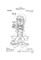
- Figure 1 is a part sectional side elevation of one form of internal combustion engine constructed in accordance with the present invention.
- Fig. 2 is a sectional end elevation.
- Fig. 3 is a fragmentary view showing one arrangement of the sparking plug, while Fig. 4: is a/diagranrshowing the cycle of operations of the pistons and sliding valves.
- a which is made of a suitable lengtliare the two working pistons Z) and b, the former being connected to the crank-shaft, c, by a connecting rod, d, in the usual manner and the latter to the crank-shaft c, by the connecting rod
- the main crank-shaft 0 is mounted as usual inthe crank-chamber a: and the auxiliary shaft 0" is mounted over the top'of the working cylinder or cylinders.
- the two crank-shafts c and c are geared together by means of any suitable gearing so thatv the The shafts and gearing with similar wheels'on a vertical shaft 7, but a chain or other positive drive might equally well be used.
- the auxiliary piston b is prolonged back,-
- gear illustrated consists of skew gear whee s e and e mounted on the two crankward so as to form a sleeve b within which the main piston b works, Portsh and h are provided in this sleeve to allow of the passage of the gases to and from the working cylinder, said portsbeing opened and.
- the sliding sleeve is which works between the auxiliary piston b and the walls of the cylinder a.
- the sleeve is is providedwith ports m and m which are so arranged as to put the inlet and exhaustports n and 'n' in the cylinder a into communicationwith the corresponding ports h and 71.” in the sleeve b at the times appropriate respectively to admission and'exhaust.
- the sleeve is has a reciprocating motion imparted to it by a crank c? on the crank-shaft 0 through a connecting rod in, suitable guides being provided to prevent it from rotating In the arrangement shown these form of pins w carried by t e cylinder a.
- the sparking plug p for igniting the in-' flammable gases may either be arranged, in-
- the increased expansion ratio is of great advantage in obtaining an increase of mechanical work for a given expenditure of fuel and by suitably modifying the design, the ratios, both of compression and expansion, may be made'to take any desired values, none of the aforesaid proportions being essential. to the invention.
- a working cylinder provided with inlet and exhaust ports, two pistons working in said cylinder, a shaft driven by the main piston, means for driving said shaft by the main piston, a shaft driven by the auxiliary piston, means for driving said shaft by the auxiliary piston a cylindrical valve sleeve provided with ports and working between said pistons, and the cylinder "all, and means for imparting motion to said valve sleeve.
- a working cylinder provided with inlet and exhaust ports
- a main piston in said cylinder driving the main crank shaft
- an auxiliary piston in said cylinder driving an auxiliary crank shaft
- a cylindrical valve sleeve provided with ports and working be tween said pistons and the cylinder wall
- means for reciprocating said valve sleeve from the auxiliary crank shaft and means for gearing the main crank shaft with the auxiliary c 'ank shaft.
- crank shaft means for gearing said crank shafts ARrHUR COWENS ALDER.
Landscapes
- Engineering & Computer Science (AREA)
- Chemical & Material Sciences (AREA)
- Combustion & Propulsion (AREA)
- Mechanical Engineering (AREA)
- General Engineering & Computer Science (AREA)
- Valve-Gear Or Valve Arrangements (AREA)
Description
J. E. SEARSJR. INTERNAL COMBUSTION ENGINE.
APPLICATION FILED DEO.28, 1909.
977,834. Patented Nov. 29,1910.
2 dIIEETE-8HEET 1.
@Wk/WW a; g
J. E. $EARS, 3n. INTERNAL COMBUSTION ENGINE.
APPLICATION FILED DEC. 28, 1909 I 9775334, Patented Nov. 29, 1910.
2 SHEETE-SHEET 2.
JOHN nnwann SEARS, JR, or NnwcAs'rLE-UPoN-rirnn, ENGLAND.
INTERNAL-COMBUSTION ENGINE.
Specification of Letters Patent.
Patented Nov. 29, 1910.
Application filed December 28, 1909. Serial No. 535,285.
To all whom it may concern: I
Be it' known. that I, JOHN EDWARD SEARs,
' Jr., B. A., a subject of the King of Great Britain and Ireland, and residing at 6 Percy Terrace, in the city of Newcastle-upon-Tyne, in the county of Northumberland, England, have invented certain new and useful Improvements in and Relating to Internal- Combustion Engines, of which the following is a specification.
This invention relates to' four stroke cycle internal combustion engines of the type in which two pistons driving separate shafts are used in the same cylinder and its object is to provide an engine of this type with a silent positive valve mechanism, in which a working stroke of expansion ratio greater than the preceding ratio of compression is followed by the completest possible mechanical scavenging.
According to this invention I combine with an engine of the above type a sliding, reciprocating, rotating, or circumferentially oscillating valve sleeve, working between the piston or pistons and the cylinder wall. At the same time by suitably proportioning the parts of the engine and by the adoption of a suitable relation between the crank angles on the two shafts, as hereinafter explained, I
secure the desired cycle of operations as indicated above.
The accompanying drawings illustrate one mode of carrying out the invention;
Figure 1 is a part sectional side elevation of one form of internal combustion engine constructed in accordance with the present invention. Fig. 2 is a sectional end elevation. Fig. 3 is a fragmentary view showing one arrangement of the sparking plug, while Fig. 4: is a/diagranrshowing the cycle of operations of the pistons and sliding valves.
In the working cylinder, a,which is made of a suitable lengtliare the two working pistons Z) and b, the former being connected to the crank-shaft, c, by a connecting rod, d, in the usual manner and the latter to the crank-shaft c, by the connecting rod, The main crank-shaft 0 is mounted as usual inthe crank-chamber a: and the auxiliary shaft 0" is mounted over the top'of the working cylinder or cylinders. -The two crank-shafts c and c are geared together by means of any suitable gearing so thatv the The shafts and gearing with similar wheels'on a vertical shaft 7, but a chain or other positive drive might equally well be used.
The auxiliary piston b is prolonged back,-
speed of rotation of 0 is onehalf that of c.
gear illustrated consists of skew gear whee s e and e mounted on the two crankward so as to form a sleeve b within which the main piston b works, Portsh and h are provided in this sleeve to allow of the passage of the gases to and from the working cylinder, said portsbeing opened and.
closed at the appropriate times by the sliding sleeve is which works between the auxiliary piston b and the walls of the cylinder a. The sleeve is is providedwith ports m and m which are so arranged as to put the inlet and exhaustports n and 'n' in the cylinder a into communicationwith the corresponding ports h and 71." in the sleeve b at the times appropriate respectively to admission and'exhaust. The sleeve is has a reciprocating motion imparted to it by a crank c? on the crank-shaft 0 through a connecting rod in, suitable guides being provided to prevent it from rotating In the arrangement shown these form of pins w carried by t e cylinder a.
The sparking plug p for igniting the in-' flammable gases may either be arranged, in-
explosive mixture contained: between the two pistons. In this way the necessity for special ignition ports in the sleeves b and Is 1s avoided.
uides take the,
The cycle of operations is clearly shown I the diagram Fig; 4. In said diagram the inlet and exhaust ports in the cylinder walls are denoted by 1 and 2 respectively, the corresponding ports in the sleeve 6 of the auxiliary piston by 3- and 4:, the correspondin ports in the sleeve is by 5 and 6, the path 0 the main pistonby 7, the path of the auxiliary piston by 8, and the range of the firing'spark by 9. In the position shown in tons are then almost in contact so that the whole of the burned'gases are driven out. In the meantime the'sliding sleeve has been rising slowly and just as this stage is reached the relative motion of this sleeve and the auxiliary piston effects the closing of the exhaust ports 12/, the inlet port it being opened inthe same fashion almost im-' mediately after. This port remains open until the two pistons attain their greatest separation on the suction stroke when the communication between the ports a and m is interrupted by .the rise of the sliding sleeve. The compression stroke now begins. 'Owing to the relative setting of the cranks of the main and auxiliary pistons the latter do not on this stroke con close together but sufiicient space is left 0 contain the compressed charge. The mixture is ex ploded by. a spark from the plug 79 in the cylinder wall, the ports at and 7a which control the inlet serving also at the appropriate time as a communication between this plug and the combustion chamber. On the explosion stroke the two pistons attain their maximum separation. Toward the end. of the wt'rking stroke the exhaust port, is opened by the movement of the sliding sleeve is which is now descending and brings the port m (already in communication with 71,) into communication with n? In the-design illustrated in the accompanying drawings the strokes of the auxiliary piston b and the sleeve k are each onehalf that of the-main piston b, the expansion ratio being 6 to land the compression ratio 4 to 1. The increased expansion ratio is of great advantage in obtaining an increase of mechanical work for a given expenditure of fuel and by suitably modifying the design, the ratios, both of compression and expansion, may be made'to take any desired values, none of the aforesaid proportions being essential. to the invention.
In engines having only one or two working cylinders it is advisable to provide a small additional fly-wheel such as 0 on the auxiliary shaft 1; to prevent the gear from chattering. It will be understood that this gear has to lie-strong enough to take the full force of the explosion and to transmit part of the power developed. Skew gears have been employed in the"example shown for the sake of silence in running, but any other suitable type ofpositive gearing may be employed. I
Having now described my invention what I claim as new ters Patent 15:
1. In an internal combustion engine the and desire to secure by Let.
combination of a working cylinder provided with inlet and exhaust ports, two pistons working in said cylinder and a cylindrical valve sleeve between said pistons and the cylinder wall.
2. In an internal combustion engine the -comb1nat1on of a worklng cylinder provided with'inlet and exhaust ports, two pistons working in said cylinder, a cylindrical-valve sleeve working between said pistons and the cylinder wall, and means for imparting mo tion to said valvesleeve.
In an internal combustion engine the combination of a working cylinder provided with inlet and exhaust ports, two pistons working in said cylinder, a shaft driven by the main piston, means for driving said shaft by the main piston, a shaft driven by the auxiliary piston, means for driving said shaft by the auxiliary piston a cylindrical valve sleeve provided with ports and working between said pistons, and the cylinder "all, and means for imparting motion to said valve sleeve.
at. In an internal combustion engine the combination of a working cylinder provided with inlet and exhaust ports, a main piston in said cylinder driving the main crank shaft, an auxiliary piston in said cylinder driving an auxiliary crank shaft, a cylindrical valve sleeve provided with ports and. working between said pistons and the cylinder wall, and means for reciprocating said valve sleeve from the auxiliary crank shaft.
In an internal combustion engine the combination of a working cylinder provided with inlet and exhaust ports, a main piston in said cylinder driving the main crank shaft, an auxiliary piston in said cylinder driving an auxiliary crank shaft, a cylindrical valve sleeve provided with ports and working be tween said pistons and the cylinder wall, means for reciprocating said valve sleeve from the auxiliary crank shaft, and means for gearing the main crank shaft with the auxiliary c 'ank shaft.
(3. In an internal combustion engine the combination of a working cylinder an auxil iz ry crank shaft a hollow cylindrical extentogether, and a fiy wheel to the auxiliary 10 $1011 or said auxiliary piston, provided with crz nk shaft. ports a main piston working 1n said C )l111- In testlmony whereof, I afhx my signature drical extension and driving the main crank in presence of two witnesses.
shaft, 9. c *lind ric: l valve sleeve provided JOHNEDVARD SEARS JR. Xi 1th ports Working between said pistons and the cylinder Wall, means for reciprocating lVitnesses:
said valve sleeve from the auxiliary crank ViLLIAM DAGGETT,
shaft, means for gearing said crank shafts ARrHUR COWENS ALDER.
Priority Applications (1)
| Application Number | Priority Date | Filing Date | Title |
|---|---|---|---|
| US53528509A US977334A (en) | 1909-12-28 | 1909-12-28 | Internal-combustion engine. |
Applications Claiming Priority (1)
| Application Number | Priority Date | Filing Date | Title |
|---|---|---|---|
| US53528509A US977334A (en) | 1909-12-28 | 1909-12-28 | Internal-combustion engine. |
Publications (1)
| Publication Number | Publication Date |
|---|---|
| US977334A true US977334A (en) | 1910-11-29 |
Family
ID=3045712
Family Applications (1)
| Application Number | Title | Priority Date | Filing Date |
|---|---|---|---|
| US53528509A Expired - Lifetime US977334A (en) | 1909-12-28 | 1909-12-28 | Internal-combustion engine. |
Country Status (1)
| Country | Link |
|---|---|
| US (1) | US977334A (en) |
Cited By (1)
| Publication number | Priority date | Publication date | Assignee | Title |
|---|---|---|---|---|
| US2451271A (en) * | 1945-08-18 | 1948-10-12 | George L Balster | V-type internal-combustion engine |
-
1909
- 1909-12-28 US US53528509A patent/US977334A/en not_active Expired - Lifetime
Cited By (1)
| Publication number | Priority date | Publication date | Assignee | Title |
|---|---|---|---|---|
| US2451271A (en) * | 1945-08-18 | 1948-10-12 | George L Balster | V-type internal-combustion engine |
Similar Documents
| Publication | Publication Date | Title |
|---|---|---|
| US1349353A (en) | Rotary engine | |
| US1197591A (en) | Internal-combustion engine. | |
| US967097A (en) | Internal-combustion engine. | |
| US1346805A (en) | Explosive-engine | |
| US1076846A (en) | Gas-engine. | |
| US1126332A (en) | Gas-motor. | |
| US681704A (en) | Gas-engine. | |
| US1253599A (en) | Gas-engine. | |
| US1160966A (en) | Internal-combustion engine with variable piston-stroke. | |
| US1112734A (en) | Rotary internal-combustion engine. | |
| US735964A (en) | Internal-combustion engine. | |
| US829231A (en) | Rotary motor. | |
| US627857A (en) | Gas-engine. | |
| US779509A (en) | Gas-engine. | |
| US1256833A (en) | Valve-gear of radial-cylinder internal-combustion. | |
| US556195A (en) | Gas or vapor engine | |
| US1120533A (en) | Internal-combustion engine. | |
| US1290925A (en) | Internal-combustion engine. | |
| US1206608A (en) | Internal-combustion engine. | |
| US1265596A (en) | Internal-combustion engine. | |
| US1059421A (en) | Internal-combustion engine. | |
| US1196598A (en) | Internal-combustion engine. | |
| US1146840A (en) | Compound internal-combustion engine. | |
| US687924A (en) | Gas-engine. | |
| US636298A (en) | Explosion-engine. |