US976896A - Amusement apparatus. - Google Patents
Amusement apparatus. Download PDFInfo
- Publication number
- US976896A US976896A US54808510A US1910548085A US976896A US 976896 A US976896 A US 976896A US 54808510 A US54808510 A US 54808510A US 1910548085 A US1910548085 A US 1910548085A US 976896 A US976896 A US 976896A
- Authority
- US
- United States
- Prior art keywords
- car
- carriage
- track
- shaft
- trolley
- Prior art date
- Legal status (The legal status is an assumption and is not a legal conclusion. Google has not performed a legal analysis and makes no representation as to the accuracy of the status listed.)
- Expired - Lifetime
Links
Images


Classifications
-
- A—HUMAN NECESSITIES
- A63—SPORTS; GAMES; AMUSEMENTS
- A63G—MERRY-GO-ROUNDS; SWINGS; ROCKING-HORSES; CHUTES; SWITCHBACKS; SIMILAR DEVICES FOR PUBLIC AMUSEMENT
- A63G7/00—Up-and-down hill tracks; Switchbacks
Definitions
- My invention relates to improvements in amusement apparatus of the class more especially intended for use in parks, gardens and other public resorts.
- My object is to provide a novel apparatus of this class which, at the same time, shall be comparatively simple in construction and economical in cost.
- the apparatus generally considered, con sists of an upright framework surrounded exteriorly by a spirally arranged track
- the trolley which is connected withthe top of the car is run out upon the spiral track and follows the latter downwardly by gravity, the car being suspended below the track and moving with the trolley which is rigidly connected with a suspension rod extending upwardly from the car proper.
- the car is equipped with the representation of a balloon to one extremity of which is connected a propeller.
- the outer portion of the framework is equipped with canvas or other fabric, a portion of which is located outside of the track and the other portion inside of the track, the object being to produce a sort of cloud effect.
- Figure l is a side elevation of the apparatus showing a car descending.
- Fig. 2 is a Vertical section taken through the apparatus, showing the car in two positions, one being in full lines and the other in dotted lines.
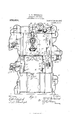
- Fig. 3 is a vertical section of the apparatus taken at right angles to Fig. 2. Thls section is taken approximately on the line 3-3, Fig. 2, the car and its attachments, however, being shown in elevation.
- Fig.4 is a detail view of the car, together with the trolley and trolley carriage, shown 011 a larger scale.
- Fig. 5 is a section taken on the line 55, Fig. a, showing the parts on a still larger scale.
- Fig. 6 is a section taken through the spiral track located on the outside of the structure, the supporting framework being shown partly broken away.
- the numeral 5 designate an upright framework of any suitable height and inclosing a vertical chamber or shaft 6 adapted to receive a car 7 composed of a basket or cage 8 and an upper portion 9 of elliptical shape and similar to the balloon member of a dirigible airship.
- a propeller 10 To one extremity of this device 9 is secured the representation of a propeller 10.
- a rod 12 which passes centrally through the balloon, its upper extremity passing through a sort of axle 13, whose extremities are equipped with journals 14 upon which are mounted wheels or rollers 15 adapted to engage track members 16 constituting the lower portion of a carriage 17 having upright side members 18 secured to a top cross piece 19 to which are attached three cables designated 20, 21 and 21, respectively.
- the central cable which is designated is adapted to pass over a loose pulley 22 mounted upon a shaft 28, the said cable also passing over a guide pulley 24k and thence down around a pulley 25 up over a pulley 26, connected by means of a support 27 with a stationary member 28 of the structure.
- this cable passes down around another pulley 29 connected with the pulley 25 by a suitable frame 30. From the pulley 25 the cable passes upwardly and is connected as shown at 31 with the supporting member of the pulley 26. Connected with the framework of the pulleys 25 and 29 is a counter-balance weight 32.
- This weight structure is adapted to counterbalance the car and by virtue of the pulley construction the weight moves but a short distance relatively to the travel of the car during the upward and down- -with the carriage.
- the rod 12, the axle 13 the wheels 15 of the car may be termed the trolley.
- This trolley which is in engagement with the cross bars 16 of the carriage, as heretofore explained, is normally locked against movement thereon by two fingers and 41, adapted to engage the periphery of one of the wheels 15 on opposite sides.
- the finger 40 may be stationary since the trolley only travels in one direction upon the carriage for the purpose of assuming its position upon the spirally arranged exterior track 42/
- the finger 41 is mounted upon a journal 43'rigidly. connected with a hand lever 44, the journal being suitably connected with one of the cross bars 16 of the carriage.
- the finger 42 is acted upon from below by a spiral spring 45 seated ina recess 46 formed in one of the track members 16.
- This spring holds the finger 41 in position to engage the periphery of one of the rollers 15 whereby the trolley is lockedagainst longitudinal travel upon the track members 16.
- the lever 44 is moved in the direction of the arrow in Fig. 4 or toward the'right sufficiently to throw the finger 41 into a groove 46 formed in one of the track members 16, whereby the finger is flush with the top of said member.
- the car may then be moved toward the left (see Fig. 2) and its trolley run out upon the spiral track 42, the rollers or wheels 15 of the trolley engaging the track members 47 of the spiraltrack, these members being separated to leave a space 48 throughwhich the suspension'rod 12travels.
- the car then movesby its own gravity down the spiral track and around the framework of the structure. on the outside until it reaches the lower extremity of the. spiral track, where it is locked against further movement by stops 49 pivoted to the framework at 50 and normally .held in the raised position by a counterbalance weight 51 connected with the pivoted stops 49 by a cable52 passing over a guide pulley 53.
- the pivoted stop members49 are drawn downwardly to the 3051- tion shown in full lines in Fig. 2. V ⁇ hen this is done the carriage is in the position shown by dotted lines in Fig. 2 and the stop members 49 are then in alinement with the track members 16 of the carriage.
- the opposite side of the shaft is also equipped with the pivoted members 49 connected by means of a cable 52 with a counter-balance weight 51. Then when the car is in place the operator or operators, by pulling down upon ropes or cables 54 connected to the members 49, may maintain the car in a predetermined position.
- the motor is started and the carriage, together with the car, is lifted vertically upwardly in the shaft until the track members 16 are brought into alinement with the members 47 of the spiral track at the top of the structure.
- the opposite extremities of the track members 16 have their ends beveled, as shown at A, to engage oppositely beveled extremities of frame members B at one end and the track members 47 at the other end.
- the car is then in position to be run out upon the spiral track, as heretofore explained, and it is only necessary to throw the lever 44 and the finger 41 into the proper position to permit this operation.
- the carriage may be lowered by reversing the motor.
- more than one car may be employed- For instance, if the structure is relatively large so that it will be practicable to have a number of cars upon the spiral track at the same time, the carriage, after moving upwardly with one car, may be quickly lowered to catch another car. In this way the carriage may be manipulated in a vertical shaft for the purpose of handling a considerable number of cars, all of which may be moving upon the spiral track at the same time.
- any car as soon as it reaches the lower extremity of the track will be locked in that position until the operator chooses to allow it to'move out uponthe carriage, as heretofore explained.
- the main framework is equipped with a sort of skeleton or light auxiliary framework which is attached to the main framework and forms a support for a canvas or other suitable fabric 61 which is given a wave-like or billowy shape.
- the upper portion of this canvas or cloud effect structure is located on the outside of the spiral track, while about midway of the structure the car runs outside of the canvas so that the cloud effect appears on the opposite side of the car. Later the latter as it approaches the lower part of the structure again passes within the canvas before reaching the lower extremity of the spiral track.
- the shaft is provided about midway between the upper and lower positions of the carriage 7 with a sort of trap door structure 67 composed of two members 68 hinged at ('39 and adapted to rise as the carriage moves upwardly and return automatically to their closed or horizontal position.
- trap door members are normally supported by cleats or bars 70 suitably supported on the framework.
- This structure would form a support or stop to the car in case anything should happen that the motor should become uncontrollable or the cables should break. In this event the car would not have far to move before coming in contact with the platform structure.
- any desired number of these safety appliances may be located in the shaft at various intervals in order to prevent any possible danger to passengers while using the apparatus.
- the trap door members 68 are equlpped with meshing segmental gears 7 6 and 77 which are rigidly secured to the platform members. These gears are located at one side of the shaft and out of the path of the basket or cage 8.
- an operating arm which is employed to open the trap door members, to allow the carriage 17 to descend after it has reached its upward limit of movement and has become detached from the car or cage, preparatory to receiving a car or cage at the bottom of the shaft. It will be understood that as the carriage moves upwardly, it engages the trap door members and opens them automatically. Vhen, however, the said members must be opened preparatory to the downward movement of the carriage, the operation must be manually performed.
- amusement apparatus the combination with a structure having a central shaft, an exteriorly located spiral track, a carriage, a car vertically movable in the shaft on said carriage, and means for transferring the car fromthe carriage to the spiral track, sub stantially as described.
- an upright structure having a central shaft for the travel of a car, an exteriorly located spiral track, a carriage vertically movable in the shaft, a car detachably connected with the carriage, means for lowering and raising the latter, and means for transferring the car from the carriage to the spiral track, substantially as described.
- Amusement apparatus comprising a framework inclosing a shaft, a spiral track exteriorly mounted upon the main framework, an auxiliary framework outside of the main framework, fabric arranged upon the auxiliary framework and given a wavelike or billowy form to produce a cloud effect, a portion of the fabric being arranged outside of the spiral track and another portion inside of the track, a carriage vertically movable in the shaft, a car provided with a trolley detachably engaging the carriage, means for elevating the carriage into alinement with the spiral track, and means for transferring the trolley of the car from the carriage to the spiral track, substantially as described.
- a car vertically movable in the shaft a portion of the shaft having transparent walls, means for discharging water in front of the transparent portion of the walls of the shaft, means for illuminating the shaft in the rear of the transparent wall portion thereof, a track spirally arranged exteriorly on the frame and having its upper and lower extremities protruding into the shaft, means for switching the car from the shaft to the track and from the track to the shaft, and means mounted exteriorly on the framework and arranged partly outside of the spiral track and partly inside thereof for producing a cloud effect, substantially as described.
- a framework having a vertical shaft, a carriage vertically movable in the shaft, a car having a trolley detachably connected with the carriage, means for raising and lowering the carriage, a trap door safety appliance intermediate the extremities of the shaft, the said appliance normally assuming the horizontal position but adapted to open when engaged by the car durin its upward movement, a spirally arrange track exteriorly mounted on the framework and having its upper and lower extremities protruding into the shaft, and means for switching the trolley of the car from the carriage to the track and from the track to the carriage, substantially as described.
Landscapes
- Types And Forms Of Lifts (AREA)
Description
W W. MQPARLAND.
AMUSEMENT APPARATUS.
APPLICATION FILED MAR. 13, 1910 976,896. Patented Nov, 29, 1910.
4 SHEETS-SHEET 1.
W. W. MQPARLAND.
AMUSEMENT APPARATUS.
APPLICATION FILED MAR.8,1910
Patented Nov. 29, 1910.
,4 SHEETSi-SHEET 2.
1m: Nam-us PETERS ca, WASHINGTON, o. 0.
W. W. MOFARLAND.
AMUSEMENT APPARATUS.
APPLICATION FILED MAR. a, 1910.
976,896. Patented Nov. 29, 1910.
4 SHEETS-SHEET 3'. 2328 2/ 3.5
THE NORRIS PETERS cm, wnsumcmu, u. c.
W. W. MOPARLAND.
AMUSEMENT APPARATUS.
Patented N 0v. 29, 1910.
APPLIUATION FILED MAR- 3, 1910 am 1' o 4 SHEETS-SHEET 4.
UNITED STATES PATENT OFFICE.
WILLIAM W. MCFARLAND, 01? DENVER, COLORADO, ASSIGNOR OF ONE-THIRD TO HARRY L. WEBER AND ONE-THIRD TO THEODORE NOLLENBERGER, OF DENVER,
COLORADO.
Application filed March 8, 1910. Serial No. 548,085.
Specification of Letters Patent.
AMUSEMENT APPARATUS.
Patented Nov. 29, 1910.
To all whom it may concern:
Be it known that I, VVILLIAM W. MOFAR- LAND, a citizen of the United States, residing in the city and county of Denver and State of Colorado, have invented certain new and useful Improvements in Amusement Apparatus; and I do declare the following to be a full, clear, and exact description of the invention, such as will enable others skilled in the art to which it appertains to make and use the same, reference being had to the accompanying-drawings, and to the letters and figures of reference marked thereon, which form a part of this specification.
My invention relates to improvements in amusement apparatus of the class more especially intended for use in parks, gardens and other public resorts.
My object is to provide a novel apparatus of this class which, at the same time, shall be comparatively simple in construction and economical in cost.
The apparatus, generally considered, con sists of an upright framework surrounded exteriorly by a spirally arranged track, the
central portion of the structure being open.
to permit a sort of car to move upwardly from the bottom, suitable power being employed to elevate the car. After it reaches the upper part of the shaft or vertical passage, the trolley which is connected withthe top of the car is run out upon the spiral track and follows the latter downwardly by gravity, the car being suspended below the track and moving with the trolley which is rigidly connected with a suspension rod extending upwardly from the car proper.
In order to add interest and fascination to the apparatus, the car is equipped with the representation of a balloon to one extremity of which is connected a propeller. These features are for appearance only.
The outer portion of the framework is equipped with canvas or other fabric, a portion of which is located outside of the track and the other portion inside of the track, the object being to produce a sort of cloud effect.
Other features of the construction will be understood by the detail explanation hereinafter given, reference being made to the accompanying drawing in which is llustrated an embodiment of the invention.
In this drawing: Figure l is a side elevation of the apparatus showing a car descending. Fig. 2 is a Vertical section taken through the apparatus, showing the car in two positions, one being in full lines and the other in dotted lines. Fig. 3 is a vertical section of the apparatus taken at right angles to Fig. 2. Thls section is taken approximately on the line 3-3, Fig. 2, the car and its attachments, however, being shown in elevation. Fig.4 is a detail view of the car, together with the trolley and trolley carriage, shown 011 a larger scale. Fig. 5 is a section taken on the line 55, Fig. a, showing the parts on a still larger scale. Fig. 6 is a section taken through the spiral track located on the outside of the structure, the supporting framework being shown partly broken away.
The same reference characters indicate the same parts in all the views.
Let the numeral 5 designate an upright framework of any suitable height and inclosing a vertical chamber or shaft 6 adapted to receive a car 7 composed of a basket or cage 8 and an upper portion 9 of elliptical shape and similar to the balloon member of a dirigible airship. To one extremity of this device 9 is secured the representation of a propeller 10. The balloon structure, together with the propeller, giving the car the appearance of an airship. Connected with the basket or cage 8 is a rod 12 which passes centrally through the balloon, its upper extremity passing through a sort of axle 13, whose extremities are equipped with journals 14 upon which are mounted wheels or rollers 15 adapted to engage track members 16 constituting the lower portion of a carriage 17 having upright side members 18 secured to a top cross piece 19 to which are attached three cables designated 20, 21 and 21, respectively. The central cable which is designated is adapted to pass over a loose pulley 22 mounted upon a shaft 28, the said cable also passing over a guide pulley 24k and thence down around a pulley 25 up over a pulley 26, connected by means of a support 27 with a stationary member 28 of the structure. From the pulley 26 this cable passes down around another pulley 29 connected with the pulley 25 by a suitable frame 30. From the pulley 25 the cable passes upwardly and is connected as shown at 31 with the supporting member of the pulley 26. Connected with the framework of the pulleys 25 and 29 is a counter-balance weight 32. This weight structure is adapted to counterbalance the car and by virtue of the pulley construction the weight moves but a short distance relatively to the travel of the car during the upward and down- -with the carriage. The rod 12, the axle 13 the wheels 15 of the car may be termed the trolley.
This trolley, which is in engagement with the cross bars 16 of the carriage, as heretofore explained, is normally locked against movement thereon by two fingers and 41, adapted to engage the periphery of one of the wheels 15 on opposite sides. The finger 40 may be stationary since the trolley only travels in one direction upon the carriage for the purpose of assuming its position upon the spirally arranged exterior track 42/ The finger 41 is mounted upon a journal 43'rigidly. connected with a hand lever 44, the journal being suitably connected with one of the cross bars 16 of the carriage. The finger 42 is acted upon from below by a spiral spring 45 seated ina recess 46 formed in one of the track members 16. This spring holds the finger 41 in position to engage the periphery of one of the rollers 15 whereby the trolley is lockedagainst longitudinal travel upon the track members 16. When, however, it is desired to run the car from the track members 16 to the spirally arranged track 42, the lever 44 is moved in the direction of the arrow in Fig. 4 or toward the'right sufficiently to throw the finger 41 into a groove 46 formed in one of the track members 16, whereby the finger is flush with the top of said member. The car may then be moved toward the left (see Fig. 2) and its trolley run out upon the spiral track 42, the rollers or wheels 15 of the trolley engaging the track members 47 of the spiraltrack, these members being separated to leave a space 48 throughwhich the suspension'rod 12travels. The car then movesby its own gravity down the spiral track and around the framework of the structure. on the outside until it reaches the lower extremity of the. spiral track, where it is locked against further movement by stops 49 pivoted to the framework at 50 and normally .held in the raised position by a counterbalance weight 51 connected with the pivoted stops 49 by a cable52 passing over a guide pulley 53.
When it is desired to allow the trolley of the car to assume its position upon the carriage, after the latter has been lowered to the proper position, the pivoted stop members49 are drawn downwardly to the 3051- tion shown in full lines in Fig. 2. V\ hen this is done the carriage is in the position shown by dotted lines in Fig. 2 and the stop members 49 are then in alinement with the track members 16 of the carriage. In order to retain the carriage and the car in the proper position in the bottom of the shaft, the opposite side of the shaft is also equipped with the pivoted members 49 connected by means of a cable 52 with a counter-balance weight 51. Then when the car is in place the operator or operators, by pulling down upon ropes or cables 54 connected to the members 49, may maintain the car in a predetermined position. As soon, however, as it is desired to start the car, the motor is started and the carriage, together with the car, is lifted vertically upwardly in the shaft until the track members 16 are brought into alinement with the members 47 of the spiral track at the top of the structure. The opposite extremities of the track members 16 have their ends beveled, as shown at A, to engage oppositely beveled extremities of frame members B at one end and the track members 47 at the other end. The car is then in position to be run out upon the spiral track, as heretofore explained, and it is only necessary to throw the lever 44 and the finger 41 into the proper position to permit this operation.
It will be understood that as soon as a car is switched off upon the spiral track, the carriage may be lowered by reversing the motor. If desired, more than one car may be employed- For instance, if the structure is relatively large so that it will be practicable to have a number of cars upon the spiral track at the same time, the carriage, after moving upwardly with one car, may be quickly lowered to catch another car. In this way the carriage may be manipulated in a vertical shaft for the purpose of handling a considerable number of cars, all of which may be moving upon the spiral track at the same time. By virtue, however, of the stop members 49 at the bottom and right hand side of the structure, any car, as soon as it reaches the lower extremity of the track will be locked in that position until the operator chooses to allow it to'move out uponthe carriage, as heretofore explained.
In order to produce a cloud efi'ect around the structure on the outside, the main framework is equipped with a sort of skeleton or light auxiliary framework which is attached to the main framework and forms a support for a canvas or other suitable fabric 61 which is given a wave-like or billowy shape. As shown in the drawing, the upper portion of this canvas or cloud effect structure is located on the outside of the spiral track, while about midway of the structure the car runs outside of the canvas so that the cloud effect appears on the opposite side of the car. Later the latter as it approaches the lower part of the structure again passes within the canvas before reaching the lower extremity of the spiral track.
In order to produce the appearance of rain within the shaft 6, the latter is pro vided with a casing of glass 62 extending a portion of the way in the shaft and provision is made for allowing water 63 to run down from a pipe 64 in front of the glass structure, the water passing into troughs 65. Outside of the glass plates incandescent lamps 66 are located for illuminating purposes and in order to add to the beauty of the effect.
As a sort of safety appliance, the shaft is provided about midway between the upper and lower positions of the carriage 7 with a sort of trap door structure 67 composed of two members 68 hinged at ('39 and adapted to rise as the carriage moves upwardly and return automatically to their closed or horizontal position. These trap door members are normally supported by cleats or bars 70 suitably supported on the framework. This structure would form a support or stop to the car in case anything should happen that the motor should become uncontrollable or the cables should break. In this event the car would not have far to move before coming in contact with the platform structure. Of course any desired number of these safety appliances may be located in the shaft at various intervals in order to prevent any possible danger to passengers while using the apparatus.
It will be understood that it will be necessary for an attendant to occupy a position upon the platform '71 in the lower part of the shaft, while another person should occupy a platform 72 on the same level with the trap door member 67. A third attendant should be placed upon the upper platform 73. The man occupying the lower position in the shaft would of course look after the receiving of the car from the lower extremity of the spiral track and controlling the starting of the same. The man upon the platform 72 will cooperate with the one upon the uppermost platform 73 in trans ferring the car and its trolley from the carriage to the spiral track. For instance the man upon the uppermost platform will manipulate the lever 44, while the man upon the lower platform will push upon the car sufficiently to cause the trolley to leave the track of the carriage and run out upon the spiral track, as heretofore explained.
The trap door members 68 are equlpped with meshing segmental gears 7 6 and 77 which are rigidly secured to the platform members. These gears are located at one side of the shaft and out of the path of the basket or cage 8. To one of the members 68 is attached an operating arm which is employed to open the trap door members, to allow the carriage 17 to descend after it has reached its upward limit of movement and has become detached from the car or cage, preparatory to receiving a car or cage at the bottom of the shaft. It will be understood that as the carriage moves upwardly, it engages the trap door members and opens them automatically. Vhen, however, the said members must be opened preparatory to the downward movement of the carriage, the operation must be manually performed.
Having thus described my invention, what I claim is:
1. In amusement apparatus, the combination with a structure having a central shaft, an exteriorly located spiral track, a carriage, a car vertically movable in the shaft on said carriage, and means for transferring the car fromthe carriage to the spiral track, sub stantially as described.
2. In amusementapparatus, the combination of an upright structure, having a central shaft for the travel of a car, an exteriorly located spiral track, a carriage vertically movable in the shaft, a car detachably connected with the carriage, means for lowering and raising the latter, and means for transferring the car from the carriage to the spiral track, substantially as described.
3. In amusement apparatus, the combination of an upright frame having a centrally located vertical shaft, an exteriorly located spirally arranged undulatory track, a carriage vertically movable in the shaft, a car having a trolley detachably connected with the carriage, means for raising and lowering the carriage, and means for transferring the trolley of the car from the carriage to the spiral track, substantially as described.
4. Amusement apparatus comprising a framework inclosing a shaft, a spiral track exteriorly mounted upon the main framework, an auxiliary framework outside of the main framework, fabric arranged upon the auxiliary framework and given a wavelike or billowy form to produce a cloud effect, a portion of the fabric being arranged outside of the spiral track and another portion inside of the track, a carriage vertically movable in the shaft, a car provided with a trolley detachably engaging the carriage, means for elevating the carriage into alinement with the spiral track, and means for transferring the trolley of the car from the carriage to the spiral track, substantially as described.
5. In amusement apparatus, the combination of a main framework inclosing a cen- &
work and having its upper and lower ex-' tremities protruding into the shaft and .adapted to assume positions of alinement with the lower portion of the carriage when 7 the latter is at its upper and lower limits of movement, and means for transferring the car trolley from the carriage to the upper extremity of the track and from the lower extremity of the track to the carriage,
substantially as described.
6. In amusement apparatus, the combination of a framework lncloslng a central shaft, a track spirally arranged exteriorly on the framework and having its upper and lower extremities protruding into the shaft, a carriage whose lower portion is composed of a track adapted to assume positions of alinement with the upper and lower extremities of the spiral track, a car equipped with a trolley engaging the lower part of the carriage and adapted to be switched from the carriage to the upper extremity of the track and from the lower extremity of the track to the carriage, means mounted on the carriage for locking the trolley in place there on, and means connected with the lower extremity of the track and forming an automatic stop. for the trolley of the car, substantially as described.
7 In amusement apparatus, the combination of a structure inclosing a vertical shaft,
a spirally arranged track exteriorly mounted on the structure and whose upper and lower extremities protrude into the shaft, a
carriage vertically movable in the shaft and the upper and lower extremities of the track having a member adapted to cooperate with where they enter the shaft, a car having a trolley connection with the carriage but readily detachable from the latter, and
erases means for switching the trolley and car from the carriage to the track and from the track to the carriage.
8. In amusement apparatus, the combination of a structure inclosing a vertical shaft,
a car vertically movable in the shaft, a portion of the shaft having transparent walls, means for discharging water in front of the transparent portion of the walls of the shaft, means for illuminating the shaft in the rear of the transparent wall portion thereof, a track spirally arranged exteriorly on the frame and having its upper and lower extremities protruding into the shaft, means for switching the car from the shaft to the track and from the track to the shaft, and means mounted exteriorly on the framework and arranged partly outside of the spiral track and partly inside thereof for producing a cloud effect, substantially as described.
9. In amusement apparatus, the combination of a framework having a vertical shaft, a carriage vertically movable in the shaft, a car having a trolley detachably connected with the carriage, means for raising and lowering the carriage, a trap door safety appliance intermediate the extremities of the shaft, the said appliance normally assuming the horizontal position but adapted to open when engaged by the car durin its upward movement, a spirally arrange track exteriorly mounted on the framework and having its upper and lower extremities protruding into the shaft, and means for switching the trolley of the car from the carriage to the track and from the track to the carriage, substantially as described.
In testimony whereof I affix my signature in presence of two witnesses.
WILLIAM V. MoFARLAND.
IVitnesses HARRY L. WEBER, THEODORE C. NOLLENBERGER, Jr.
Priority Applications (1)
| Application Number | Priority Date | Filing Date | Title |
|---|---|---|---|
| US54808510A US976896A (en) | 1910-03-08 | 1910-03-08 | Amusement apparatus. |
Applications Claiming Priority (1)
| Application Number | Priority Date | Filing Date | Title |
|---|---|---|---|
| US54808510A US976896A (en) | 1910-03-08 | 1910-03-08 | Amusement apparatus. |
Publications (1)
| Publication Number | Publication Date |
|---|---|
| US976896A true US976896A (en) | 1910-11-29 |
Family
ID=3045274
Family Applications (1)
| Application Number | Title | Priority Date | Filing Date |
|---|---|---|---|
| US54808510A Expired - Lifetime US976896A (en) | 1910-03-08 | 1910-03-08 | Amusement apparatus. |
Country Status (1)
| Country | Link |
|---|---|
| US (1) | US976896A (en) |
-
1910
- 1910-03-08 US US54808510A patent/US976896A/en not_active Expired - Lifetime
Similar Documents
| Publication | Publication Date | Title |
|---|---|---|
| US1849226A (en) | Submarine amusement device | |
| US931863A (en) | Amusement apparatus. | |
| US2315323A (en) | Selective machine | |
| US976896A (en) | Amusement apparatus. | |
| US633215A (en) | Elevator. | |
| US931702A (en) | Traveling fire-escape. | |
| US1502699A (en) | Amusement railway | |
| US1261691A (en) | Elevator. | |
| US691719A (en) | Balloon-observatory. | |
| US753197A (en) | Willaed h | |
| US868117A (en) | Movable fire-escape for buildings. | |
| US749736A (en) | jetley | |
| US467289A (en) | Hoisting apparatus | |
| US530128A (en) | Illusion apparatus | |
| US1207914A (en) | Amusement apparatus. | |
| US491130A (en) | Cash and parcel carrier apparatus | |
| US411847A (en) | Toy elevator | |
| US1253832A (en) | Automatic guard and circuit-breaker. | |
| US945748A (en) | Emergency-exit for suspension-railway cars. | |
| US755879A (en) | Combined stage and circus-ring. | |
| US595951A (en) | Illusion apparatus | |
| US1407138A (en) | Self closing and opening gate for elevators | |
| US725509A (en) | Scenic apparatus. | |
| US338735A (en) | Combined pool-rack and ball-spotter | |
| US546927A (en) | Theatrical device for producing illusory effects |