US976836A - Electric annunciating apparatus. - Google Patents
Electric annunciating apparatus. Download PDFInfo
- Publication number
- US976836A US976836A US48425909A US1909484259A US976836A US 976836 A US976836 A US 976836A US 48425909 A US48425909 A US 48425909A US 1909484259 A US1909484259 A US 1909484259A US 976836 A US976836 A US 976836A
- Authority
- US
- United States
- Prior art keywords
- annunciator
- room
- door
- indicator
- circuit
- Prior art date
- Legal status (The legal status is an assumption and is not a legal conclusion. Google has not performed a legal analysis and makes no representation as to the accuracy of the status listed.)
- Expired - Lifetime
Links
Images
Classifications
-
- G—PHYSICS
- G08—SIGNALLING
- G08B—SIGNALLING SYSTEMS, e.g. PERSONAL CALLING SYSTEMS; ORDER TELEGRAPHS; ALARM SYSTEMS
- G08B5/00—Visible signalling systems, e.g. visible personal calling systems or remote indication of seats occupied
- G08B5/22—Visible signalling systems, e.g. visible personal calling systems or remote indication of seats occupied using electric transmission; using electromagnetic transmission
- G08B5/36—Visible signalling systems, e.g. visible personal calling systems or remote indication of seats occupied using electric transmission; using electromagnetic transmission using visible light sources
Definitions
- My invention relates to electric annunciators and ine-ans for operating the same.
- My invention is particularly adapted for indicating occupancy or non-occupancy of an apartment or room; whether or not an apartment or room is taken or let; and for similar announcements.
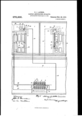
- Figure 1 is a diagrammatic View illustrating in section the lower fioor of a building containing an electric battery and a number of annunciators, and the outside of a door to a room or apartment and the in side of a door to a room or apartment, and an annunciator outside of each of said doors, and-the several circuits connecting the battery with the locks and bolts on the doors and With the annunciators.
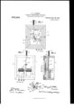
- Fig. 2 is a front elevation of .one of the annunciators, such as is shown inthe lower part of Fig.
- Fig. 3 is a rear elevation of the same.
- Fig. 4 is a central vertical section of the annunciator shown in Figs. 2 and 3.
- Fig. 5 is a detail showing the annunciator hands and means for operating the same.
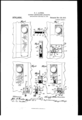
- Fig. 6 is a front elevation reatl'y enlarged of the lock on the outside og a door, such as is shown in the upper left hand portion of Fig. 1, but near the oppositehedg'eof thedoor to that shown in Fig. 1.
- Fig. 7 is a similar View, but With part of the lock casingbroken away so as to showthe operative parts of the lock.
- Fig. 8 is a vertical section enlarged of the lock shown in Fig. 7.
- Fig. 9 is an enlarged detail o the two contacts otI the lock shown in Fig. 7, and the circuit closer.
- Fig.. 10 is a iront elevation greatly enlarged of the lock and part of the inside. oi. a door such as is shown in the upper right-hand corner of Fig. 1, hut with the lock and bolt near the edge of the door opposite to that shown in said figure.
- Fig. 11 is a similar View to Fig. 10, hut with the front plates of the lock and holt removed so as to show the electrical contacts.
- Fig. 12 is a vertical section through the electric contacts shown in Fig. 1l.
- Fig. 13 is a vertical section greatly enlarged of the movable portions of the bolt shown in Figs. 10 and 11.
- Fig. 14 is a key such as may be used for making contact with the electric contacts shown in Figs. 11 and 12.
- FIG. 1, 1 represents a portion of the building in which is seen the outside of a door and an annunciator over the same. This may be in t-lie'hall of a hotel or other building.
- 2 represents a. portion of a hotel or other building such as the inside of a room or apartment, showing the insidecf .a door. It may be the saine door as'shownin the portion 1 of the building or the inside of' some other door'. Said d'dors are' repre ⁇ sented by 3.
- the annuncia't-ors 5 are very similar toj the annunci'ators 4,. but 1not li'aV-' ing all the featuresV offan'nuiiiciator's t.A
- FIG. 13 is the frame of the annunciator, see Figs. 2, 3 and 4, 14 is the room or apartment designation on the face of the annunciator, shown in Fig. 2 as 411.
- 15 is a designation on the f ace of the annunciator 4 marked Out
- 16 is a designation on the face of the annunciator marked In 17 is the indicator or annunciator hand which is fixed to a sleeve 18 and provided with an extension 19 extending from said sleeve in a direction opposite to that of the hand 17.
- the sleeve 18 is journaled to a shaft 2O which passes through said sleeve and face of the annunciator.
- 21 and 22 are pins extending outwardly from the annunciator face, and adapted to stop the hand 17 at the proper places to indicate Out and In respectively.
- Let 24 is an indicator, or annunciator hand, secured to the shaft 20.
- 27 is a stop extending from the face of the annunciator to limit the downward move-v ment of the hand 24.
- 28 and 29V are two solenoid magnets secured to the annunciator 4 back of the base of the same, and 30 is a core extending into said magnets to be drawn respectively by the same.
- the back of the pin 25 is secured to said core' ⁇ 31 is a vertically movable rod extending through a vertically guiding opening 32 in the frame 13 and through a guide 33 below said opening 32.
- the lower end oi? said rod 31 is provided with a forward extension 34, which projects over the extension 26 of the arm 24, passing through an inclined slot 35 in the facel of the annunciator.
- the upper ortion of the rod 31 extends beyond thefiiame 13, and is surrounded above said frame by a tension s ring 36, a head 37 on the end of said rod olding said spring in place.l
- 4l is a block of electrical insulation secured inside of the lock casing 7. Secured to said block are two spring electrical contacts, 42 and 43, secured to said block a short distance from each other.
- the bolt of the lock is the bolt of the lock, provided with a circuit closer or contact 45, for making electrical connection alternately with the contacts 42 and 43.
- a circuit closer or contact 45 is shown back and out of contact with contact 42.
- the other parts ci the lock in casing 7 are those of an ordinary lock and form no part of this invention. I have shown the casin 7 with its lock, contacts, etc., as attache to the outside of the door 3.
- a tube 47 of electric conducting material Secured to the front portion oit the casing 8, around and close to the upper part 46 of the keyhole, is a tube 47 of electric conducting material, provided with a longitudinal slot in its lower portion, see Fig. 11, so that when the key is inserted through the keyhole with the shank of the key in said tube, the lateral portion or bit of said 'key will pass through. the slot, and the key will make contact with said tube.
- a hub or fixed sleeve 53 Extending outwardly from the support 9 of the bolt, and on the inside of the door, is a hub or fixed sleeve 53.
- 56l is a cap secured to or forming part of the bolt 54, and adapted to rotate when said bolt is turned.
- 57 is a pin of electric conducting material secured to the cap 56 and extending inward and toward the support 9.
- 58 and 59 are two spring terminal contacts separated from each other and secured to insulated blocks 60, secured to the support 9.
- the cap 56 covers up said contacts, insulated blocks and pin.
- the cap 56 isv held in place with its spindle 55 inside of sleeve 53, in any appropriate manner, as for example, by means of a screw passing through the support 9 and into the spindle 55, as shown in Fig. 13.
- Fig. 14 illustrates the key which is used as a circuit closer in the lock 8.
- the annunciator 5 such as is to be used over the door on the outside of a room, dispenses with the designation Let and the indicator hand 24, 26 and its connecting parts, the stop 27, the rod 31 and its Vconnections.
- 61, 62 and 63 are three terminals, 61 and 63 being connected with one pole of the battery 64, and 62 being connected with the opposite pole of said attery.
- the indicator hand 1. When the door is locked on the outside b the outside lock 7, the indicator hand 1.( will oint to the indicator 15 for Out both 1n the managers o'liice, (as shown by all the annunciators except one at the bottom ot Fig. 1,) and ou the annunciator over the door.
- the making electric connection with the Contact 43 Will make a circuit from the battery 64 through the line 65 and hinge 6 to the lock 7 and then to the bolt 44 and circuit breaker 45, then to the contact 43 and from thence to the line 66 to the solenoid 290i annunciator 4, and then through line 67 to battery 64, and from the line 66 to the terminal 63 of the" annunciator 5, and from thence tothe solenoid 29 of said annunciator, then to the terminal 62, and from thence through the line 72 to the opposite pole of the battery 64, thus completing the circuit through the solenoids 29 of both annunciators 4 and 5, and pulling the core 30 I and the pin 25, which would tend to draw the hand 17 in the direction of the Out designation 15; but as the hand 17 is alminal 42, line 68, terminal 38 and annunci-V ator 4, solenoid 28 of said annunciator, line 69, line G7, to the opposite pole of the battery, thus lcompleting the circuit through said solenoid.
- a circuit is also made through line 68 and terminal 61, to the solenoid 28 of annunciator 5, and from thence through terminal 62 and lines 72 and 67 to the opposite pole of the battery, thus completing said circuit.
- the completion of the circuits through the solenoids 28 in both annunciators will cause the cores 30 of the saine to be drawn toward said solenoids, thereby forcing the hands 17 of both of said ani'iui'iciators over to the vIn designation 16, and so that both of said armunciators will announce that the tenant is in his room or apartment.
- a still further insertionof the key will cause the saine to Contact With the terminals 50, 52, and the circuit will then pass through lines 65, 5:3, to lock 8, tube 47, key 70, 71, contacts 50, 52, to line 7G, and thence to annunciator 5 and through solenoid 28 in said annunciator, then back through line 7 5 and return line 72, thus completing the circuit through solenoid 28 and drawing the arm 17 over to the In designation 16. The annunciator will then announce that the tenant is occupying his room. By a little further insertion of the key the bit 71 Will pass the contacts 50, 52 and the circuit will be broken and the solenoid denergized. The key is then in a position to lock the door.
- the pin 57 Will next come in Contact With the terminal 58, and the circuit will be completed through lines 65, 73, 77, support 9, cap 56, pin 57, terminal 58, lines 79 and 7 G, to annunciator 5, and through the solenoid 28 and back through the return lines 75 and 72, thus completing the circuit through said solenoid and forcing the hand 17 over to the In designation 16.
- the pin 57 passes the contact 79 the circuit Will be broken.
- the bolt is turned in the reverse direction or unbolted, the above operation Will be reversed, and when the bolt is thrown back, the hand 17 Will be forced to the Out designation 15, and the door being unfastened, the annunciato'r Will announce that the tenant has left his room.
- any of the fastening devices above described that is, the lock 7 on the outside of the door, or the lock 8 on the inside of the door, or the bolt l0 on the inside of the door, may be used Without the others. It is also obvious that if the inside fastening or fastenings are used Without the outside ones, an annunciator like F ig. 4 can be used in the managers ofiice in addition 4to the annunciator 5 outside the apartment. It Will also be evident that either the annunciator 4 or the annunciator 5 can be used Without 'the other.
- G The combination of an indicator to indicate whether a room is occupied or unoccupied, a locking device for the door of said room, a plurality of electric circuits connected With said indicator so as to operate t-he same, make and break devices in said circuits connected with the locking device, whereby the operation oi the locking device makes and breaks said circuits and operates said indicator, and an additional indicator, constructed, When in a certain position, to be automatically moved to another position to indicate that the room has been let, when the first indicator is moved to indicate that the room is occupied.
- an indicator t-o indicate whether a room is occupied or unoccupied, a locking device for the door of said room, a plurality of electric circuits connected With said indicator so as to operate the same, make and break devices in said circuits connected With the locking device, whereby the operation of the locking device makes and breaks said circuits and operates said indicator, and an additional indicator, constructed, When'in a certain position, to be automatically moved to another position When the first indicator is moved to one of' its positions.
- an annunciator to indicate Whether a room is occupied or unoccupied, a locking device for the door of said room, a plurality of electric circuits, an electro-magnet forming part of each circuit, a movable indicator arranged to be operated by said magnets, a circuit closer connected with the locking device for closing and breaking the circuits through the respective magnets, and thereby operating the indicator, a movable device constructed, when in a certain position, to be moved to another position by the movement of said indicator to a certain position, and means for returnA ing said device to its first position.
- an annunciator to indicate whether a room is occupied or unoccupied, a locking device for the door of said room, a plurality of electric circuits, an electro-magnet forming part of each circuit, a movable indicator arranged to be operated by said magnets, a circuit closer connected with the locking device for closing and breaking the circuits through the respective magnets, and thereby operating the indieatoi', a Amovable device constructed, when in a certain position, ,to be moved to another position by said indicator when moving to a certain osition, and means for returning said device to its rst position.
Landscapes
- Physics & Mathematics (AREA)
- Electromagnetism (AREA)
- General Physics & Mathematics (AREA)
- Lock And Its Accessories (AREA)
Description
H. J. ALTHER.
ELECTRIC ANNUNGIATING APPARATUSl PPLIUTION FILED IAB.18 1909. 976,836. Patented Nov. 29. 1910.
3 SHEETS-SHEET 1.
IIIIIII I l l I Il H. J. ALTHER. ELEGTRIG ANNUNUIATING APPARATUS'. APPLIUATION FILED MAn.1.19o9.
976,836. Patented Nov.29,1910.
3 SHEETS-SHEET 2.
29 @wf M v me/Wife@ THE Hemus rnnrs cn.. wAsHmoraN.-n. c.
H. J. ALTHER.
ELECTRIC ANNUNOIATING APPABTUS.
APPLIOATION FILED IAB.. 18, 1909v 976,836. Patented N0v.29, 1910.
3 SHEETS-SHEETS.
gral a,
rits Naluzls rlrrns ca., wAsmnqsroN. ac.
UNTTEI) STATES PATENT OFFICE.
HENRY JACOB ALTHER, OF BOSTON, MASSACHUSETTS, ASSIGNOR OF ONE-HALF TO GEORGE W. GILL, OF MEDFORD, MASSACHUSETTS.
ELECTRIC ANNUNCIATING APPARATUS.
Application filed March 18, 1909.
To all whom 'it 'may concern.'
Be it known that I, HENRY Jacon ALTHER, a citizen of the United States, and a resident oi the city of Boston, county ofi Suffolk, State oi Massachusetts, have invented certain new and useful Electric Annunciating Apparatus, of which the following is a. specification.
My invention relates to electric annunciators and ine-ans for operating the same.
My invention is particularly adapted for indicating occupancy or non-occupancy of an apartment or room; whether or not an apartment or room is taken or let; and for similar announcements.
In hotels it is very desirable that at. the clerks or similar oilice the fact of the occupancy or non-occupancy of a room or apartment should be instantly indicated, and either 'at said oflice or at the office of the manager, should also be instantly indicated the fact of a. room or apartment being taken or let.
I have shown in the accompanying drawings an embodiment of my invention, to indicatie the occupancy and non-occupancy of' a room or apartment, and the letting and non-letting of the same, in which Figure 1 is a diagrammatic View illustrating in section the lower fioor of a building containing an electric battery and a number of annunciators, and the outside of a door to a room or apartment and the in side of a door to a room or apartment, and an annunciator outside of each of said doors, and-the several circuits connecting the battery with the locks and bolts on the doors and With the annunciators. Fig. 2 is a front elevation of .one of the annunciators, such as is shown inthe lower part of Fig. 1, and adapted tov be used in the managers oliice of the hotel or other building. Fig. 3 is a rear elevation of the same. Fig. 4 is a central vertical section of the annunciator shown in Figs. 2 and 3. Fig. 5 is a detail showing the annunciator hands and means for operating the same. Fig. 6 is a front elevation reatl'y enlarged of the lock on the outside og a door, such as is shown in the upper left hand portion of Fig. 1, but near the oppositehedg'eof thedoor to that shown in Fig. 1. Fig. 7 is a similar View, but With part of the lock casingbroken away so as to showthe operative parts of the lock. Fig.
Specification of Letters Patent.
Patented Nov. 29, 1910. serial N0. 484,259.
8 is a vertical section enlarged of the lock shown in Fig. 7. Fig. 9 is an enlarged detail o the two contacts otI the lock shown in Fig. 7, and the circuit closer. Fig.. 10 is a iront elevation greatly enlarged of the lock and part of the inside. oi. a door such as is shown in the upper right-hand corner of Fig. 1, hut with the lock and bolt near the edge of the door opposite to that shown in said figure. Fig. 11 is a similar View to Fig. 10, hut with the front plates of the lock and holt removed so as to show the electrical contacts. Fig. 12 is a vertical section through the electric contacts shown in Fig. 1l. Fig. 13 is a vertical section greatly enlarged of the movable portions of the bolt shown in Figs. 10 and 11. Fig. 14 is a key such as may be used for making contact with the electric contacts shown in Figs. 11 and 12.
Similar characters represent like parts in all the figures.
Referring to Fig. 1, 1 represents a portion of the building in which is seen the outside of a door and an annunciator over the same. This may be in t-lie'hall of a hotel or other building.
2 represents a. portion of a hotel or other building such as the inside of a room or apartment, showing the insidecf .a door. It may be the saine door as'shownin the portion 1 of the building or the inside of' some other door'. Said d'dors are' repre` sented by 3.
4 is an aniiunciator, seiferal being shown in a. portion ofthe building d itferent from 1 and 2,A as for example, the managers room of a hotel. l I have shownanuinber of said annunciators, therebeiiig one foreach room or apartment occupied orto be occupied'by tenants.
5 represents an annunciator to be situated preferably above the door loutside of the apartment. The annuncia't-ors 5 'are very similar toj the annunci'ators 4,. but 1not li'aV-' ing all the featuresV offan'nuiiiciator's t.A
6 represents the hinges of the doors 3, 7 the casing of the outerlock, and 8 the casing of the inner lock of said doors.
9 is a support for the movable portions ofthe bolt'on the vinside of the door 3, and
10 is the holding portion' 1of the same.
11 `are ordinary spring contacts .on theedge" of the door 3 for making electricaly tending' connection with terminals or contacts 12 in the frame of the door when the same is closed.
13 is the frame of the annunciator, see Figs. 2, 3 and 4, 14 is the room or apartment designation on the face of the annunciator, shown in Fig. 2 as 411.
15 is a designation on the f ace of the annunciator 4 marked Out, and 16 is a designation on the face of the annunciator marked In 17 is the indicator or annunciator hand which is fixed to a sleeve 18 and provided with an extension 19 extending from said sleeve in a direction opposite to that of the hand 17. The sleeve 18 is journaled to a shaft 2O which passes through said sleeve and face of the annunciator.
21 and 22 are pins extending outwardly from the annunciator face, and adapted to stop the hand 17 at the proper places to indicate Out and In respectively.
23 is a designation on the face of the annunciator marked Let 24 is an indicator, or annunciator hand, secured to the shaft 20.
25 is a pin extending through the extension 19 of the arm 17, adapted to ride against the cam shaped rearward extension 26 of the arm 24, so that when said extension moves in a direction away from the designation Let the hand 24 will be forced over so as to point to or indicate the designation t 77.
27 is a stop extending from the face of the annunciator to limit the downward move-v ment of the hand 24.
28 and 29V are two solenoid magnets secured to the annunciator 4 back of the base of the same, and 30 is a core extending into said magnets to be drawn respectively by the same. The back of the pin 25 is secured to said core'` 31 is a vertically movable rod extending through a vertically guiding opening 32 in the frame 13 and through a guide 33 below said opening 32. The lower end oi? said rod 31 is provided with a forward extension 34, which projects over the extension 26 of the arm 24, passing through an inclined slot 35 in the facel of the annunciator. The upper ortion of the rod 31 extends beyond thefiiame 13, and is surrounded above said frame by a tension s ring 36, a head 37 on the end of said rod olding said spring in place.l
38,l 39. arid'40 are electric terminals exv l y'ond the frame 13.
4l is a block of electrical insulation secured inside of the lock casing 7. Secured to said block are two spring electrical contacts, 42 and 43, secured to said block a short distance from each other.
44 is the bolt of the lock, provided with a circuit closer or contact 45, for making electrical connection alternately with the contacts 42 and 43. In Figs. 7 and 9 of the drawings the circuit closer 45 is shown back and out of contact with contact 42. The other parts ci the lock in casing 7 are those of an ordinary lock and form no part of this invention. I have shown the casin 7 with its lock, contacts, etc., as attache to the outside of the door 3.
Secured to the front portion oit the casing 8, around and close to the upper part 46 of the keyhole, is a tube 47 of electric conducting material, provided with a longitudinal slot in its lower portion, see Fig. 11, so that when the key is inserted through the keyhole with the shank of the key in said tube, the lateral portion or bit of said 'key will pass through. the slot, and the key will make contact with said tube.
48 is a block of insulation inclosed in the casing 8 and provided with and to which are secured two arms 49, 50, of electric conducting material, said arms being separated from each other, and extending around, as at 51, the tube 47, and provided with downwardly extending spring tongues 52.
Extending outwardly from the support 9 of the bolt, and on the inside of the door, is a hub or fixed sleeve 53.
54 is the bolt proper, which is provided with a hollow spindle 55 extending into the fixed sleeve 53 and which sleeve forms a journal bearing for said spindle.
56l is a cap secured to or forming part of the bolt 54, and adapted to rotate when said bolt is turned.
57 is a pin of electric conducting material secured to the cap 56 and extending inward and toward the support 9.
58 and 59 are two spring terminal contacts separated from each other and secured to insulated blocks 60, secured to the support 9. The cap 56 covers up said contacts, insulated blocks and pin. The cap 56 isv held in place with its spindle 55 inside of sleeve 53, in any appropriate manner, as for example, by means of a screw passing through the support 9 and into the spindle 55, as shown in Fig. 13.
Fig. 14 illustrates the key which is used as a circuit closer in the lock 8. The spindle of the key and its point making contact with the tube 47, and the bit of the key making contact respectively with the tongues 52 of the contacts 49 and 50.
The annunciator 5, such as is to be used over the door on the outside of a room, dispenses with the designation Let and the indicator hand 24, 26 and its connecting parts, the stop 27, the rod 31 and its Vconnections.
61, 62 and 63 are three terminals, 61 and 63 being connected with one pole of the battery 64, and 62 being connected with the opposite pole of said attery.
masse When the door is locked on the outside b the outside lock 7, the indicator hand 1.( will oint to the indicator 15 for Out both 1n the managers o'liice, (as shown by all the annunciators except one at the bottom ot Fig. 1,) and ou the annunciator over the door.
When the door 3 is unlocked from the outside by the outside lock 7, the 'indicator' hand 17 Will point to the indication 16 for 1n on the ain'iunciators both in the managers oliice and on the place over the door of the room, as will be seen on the left-hand upper indicator' 4 at the managers office and the indicator 5 at the upper left-hand portion of Fig. 1. The movement of the arm 17 in turning to the designation In at 16, will, by means of the pin 25 riding over the arm 26 (see Fig. 2) force the arm 24 to the right, and cause said arm to pointto the designation 28, Let This will be indicated in the managers office, as shown on the upper lefthand indicatorI on the lower part of Fig. 1. Said annunciator indicates to the manager that the particular room that said annunciator connects with, is taken or let, and also that its tenant is occupying said room.
YVhen the key is inserted in the hole of the lock 7, and the bolt- 44 is turned back to unlock the door, the circuit closer 45 will first come in contact With the terminal contact 43, said circuit closer Will then become disconnected With contact 43 and then bec-ome connected With the contact- 42 and then clear said contact. The making electric connection with the Contact 43 Will make a circuit from the battery 64 through the line 65 and hinge 6 to the lock 7 and then to the bolt 44 and circuit breaker 45, then to the contact 43 and from thence to the line 66 to the solenoid 290i annunciator 4, and then through line 67 to battery 64, and from the line 66 to the terminal 63 of the" annunciator 5, and from thence tothe solenoid 29 of said annunciator, then to the terminal 62, and from thence through the line 72 to the opposite pole of the battery 64, thus completing the circuit through the solenoids 29 of both annunciators 4 and 5, and pulling the core 30 I and the pin 25, which would tend to draw the hand 17 in the direction of the Out designation 15; but as the hand 17 is alminal 42, line 68, terminal 38 and annunci-V ator 4, solenoid 28 of said annunciator, line 69, line G7, to the opposite pole of the battery, thus lcompleting the circuit through said solenoid. A circuit is also made through line 68 and terminal 61, to the solenoid 28 of annunciator 5, and from thence through terminal 62 and lines 72 and 67 to the opposite pole of the battery, thus completing said circuit. The completion of the circuits through the solenoids 28 in both annunciators will cause the cores 30 of the saine to be drawn toward said solenoids, thereby forcing the hands 17 of both of said ani'iui'iciators over to the vIn designation 16, and so that both of said armunciators will announce that the tenant is in his room or apartment. The movement of the hand 17 in the annunciator 4 over to the In designation, Will cause the pin 25 to ride over the cam edge of the arm 26, and thus force the arm 24 over to the Let designation, so that the annunciator 4 will also announce that the room that said annunciator connects with, is let. Just as soon,in unlocking the door, as the circuit closer 45 passes beyond the contact 42, all the circuits are broken. When thc occupant of the room leaves his room and starts to lock the door, the circuit closer 45 comes in contact with the terminal 42, and the circuit is made through the solenoids 28 of both annunci.- ators, but as the cores 80 have already been drawn into or toward said annunciators and the hand 17 to the In designation, said annunciators Will not. be affected. The next movement of the bolt will cause the circuit closer 45 to come in Contact With the terminal 43, and the circuit Will then be made through the solenoids 29 of both annunciators 4 and 5, as has been above described, the cores BO Will then be drawn into or toward the solenoids 29, and the arm 17 of each of said annunciators Will be forced over to the Out designation 15, as shown in Fig. 2. The annunciators 4 and 5 Will announce that the tenant is out of his apartment or room. If the manager has been inormedthat the room or apartment is given up, he presses down the rod 31 of the annunciator 4, and through its forwardektension 34, pressing down on the extension 26 of the arm 24 will draw said arm up and away from the Let designation 23, so that there 115 Will not be any announcement o-n t-he annunciat-or 4 that the particular room or apartment is let.
"When the tenant is inside of his room, if he inserts the key, see 70, into keyhole 46, 120 the shank of said key Will come in contact with the tube 47, and the bit 71 Will first come in contact With the contacts 49, 52, thus making the circuit from the line 65 7 3, lock 8, tube 47, key -71, contacts 49 and 125 52, line 74, annunciator 5, solenoid 29 of said annunciator, line 75 and return line 72, thus' completing the circuit through said solenoid, and drawing the hand 17 over to the Out indication 1'5. The further insertion of the 130 I key 70, 71 will pass the contacts 49, 52, and the circuit will be broken, thus denergizing the solenoid 29. A still further insertionof the key will cause the saine to Contact With the terminals 50, 52, and the circuit will then pass through lines 65, 5:3, to lock 8, tube 47, key 70, 71, contacts 50, 52, to line 7G, and thence to annunciator 5 and through solenoid 28 in said annunciator, then back through line 7 5 and return line 72, thus completing the circuit through solenoid 28 and drawing the arm 17 over to the In designation 16. The annunciator will then announce that the tenant is occupying his room. By a little further insertion of the key the bit 71 Will pass the contacts 50, 52 and the circuit will be broken and the solenoid denergized. The key is then in a position to lock the door. Vhen the tenant desires t-o leave the room, the door has to be unlocked, and in taking out the key, the saine passing the two contacts 50 and 49 will first coinplete the circuit through 50 and the solenoid 28, but the indicating hand 17 being at In it Will not be moved. W hen the key comes in contact with terminal 49 the circuit Will be completed through solenoid 29, and the hand 17 will be forced over to the Out designation. The Withdrawal of the key from the key-hole 49, Will break the circuit, and the door being unlocked, the annunciator will indicate that the tenant is out.
It the tenant instead of using the key to fasten the door when he is in his room, turned the bolt 54, the pin 57 will first come in contact with terminal 59, and the circuit will be made through lines 65, 73, 77, bolt support 9, cap 5G, pin 57, contact 59, lines 78 and 74, to annunciator 5 and the solenoid 29 of said annunciator, and return lines and 72, thus completing the circuit through solenoid 29, and drawing the hand 17 to the Out designation 15. The pin 57 Will next come in Contact With the terminal 58, and the circuit will be completed through lines 65, 73, 77, support 9, cap 56, pin 57, terminal 58, lines 79 and 7 G, to annunciator 5, and through the solenoid 28 and back through the return lines 75 and 72, thus completing the circuit through said solenoid and forcing the hand 17 over to the In designation 16. When. the pin 57 passes the contact 79 the circuit Will be broken. When the bolt is turned in the reverse direction or unbolted, the above operation Will be reversed, and when the bolt is thrown back, the hand 17 Will be forced to the Out designation 15, and the door being unfastened, the annunciato'r Will announce that the tenant has left his room.
It will, of course, be obvious that any of the fastening devices above described, that is, the lock 7 on the outside of the door, or the lock 8 on the inside of the door, or the bolt l0 on the inside of the door, may be used Without the others. It is also obvious that if the inside fastening or fastenings are used Without the outside ones, an annunciator like F ig. 4 can be used in the managers ofiice in addition 4to the annunciator 5 outside the apartment. It Will also be evident that either the annunciator 4 or the annunciator 5 can be used Without 'the other.
From the above it Will be clearly seen that the ordinary act of the occupant of the room, especially of a hotel, when he enters or leaves the same Will immediately indicate on the annunciator or annunciators the fact that the tenant is occupying his room or has left it. l
It Will of course be evident that the precise means as above described and shown in the drawings need not be used to carry out my invention, as many other means may be used for this purpose.
What I claim as new and desire to secure by Letters Patent is 1. The combination of an annunciator to indicate Whether a room is occupied or unoccupied, a door to said room provided With an opening, a plurality of electric circuits connected with said annunciator so as to operate the same, and make and break devices in said circuits connected With said door, and means for operating said devices and for insertion Within said opening, Whereby the operation of said means makes and breaks said circuits and operates the annunciator.
2. 'Ihe combination of an annunciator to indicate Whether a room is occupied or unoccupied, a door to said room, a lock casing secured to said door, and provided With an opening', a plurality of electric circuits connected With said annunciator so as to operate the same, and make and break devices in said circuits and inclosed Within said casing, whereby means may be inserted Within said opening and caused to operate said devices to make and break said circuits and operate the annunciator.
3. The combination of an annunciator to indicate Whether a room is occupied or unoccupied, la door to said room, a lock casing secured to said door, and provided With an opening, a plurality of electric circuits connected with said annunciator so as to operate the same, and make and break devices in said circuits and inclosed Within said casing, and inea-ns for operating said devices and for insertion Within said opening, whereby the circuits may be made and broken and the annunciator may be operated.
4. The combination of an annunciator to indicate Whether a room is occu ied Aor unoccupied, a door to said room, a ook casing secured to said door, and provided with an opening, a plurality of electric circuits connected With said annunciator so as to operate the same, terminal contacts connected respectively with the two circuits of the annunciator, and inclosed within said casing, and a Contact secured to the bolt in the casing and adapted to contact With said terminals, whereby the operation of the bolt will make and break said circuits and operate the annunciator.
5. The combination of an annunciator to indicate Whether a room is occupied or un occupied, a door to said room, a lock casing secured to said door, and provided With an opening, a plurality of electric circuits connected with said annunciator so as to opcrate the same, terminal spring contacts connected respectively With the tWo circuits of the annunciator, and inclosed Within said casing, and a contact secured to the bolt in the casing and adapted to contact with said terminals, whereby the operation of the bolt will make and break said circuits and operate the annunciator.
G. The combination of an indicator to indicate whether a room is occupied or unoccupied, a locking device for the door of said room, a plurality of electric circuits connected With said indicator so as to operate t-he same, make and break devices in said circuits connected with the locking device, whereby the operation oi the locking device makes and breaks said circuits and operates said indicator, and an additional indicator, constructed, When in a certain position, to be automatically moved to another position to indicate that the room has been let, when the first indicator is moved to indicate that the room is occupied.
7. The combination of an indicator t-o indicate whether a room is occupied or unoccupied, a locking device for the door of said room, a plurality of electric circuits connected With said indicator so as to operate the same, make and break devices in said circuits connected With the locking device, whereby the operation of the locking device makes and breaks said circuits and operates said indicator, and an additional indicator, constructed, When'in a certain position, to be automatically moved to another position When the first indicator is moved to one of' its positions.
S. The combination of an annunciator to indicate Whether a room is occupied or unoccupied, a locking device for the door of said room, a plurality of electric circuits, an electro-magnet forming part of each circuit, a movable indicator arranged to be operated by said magnets, a circuit closer connected with the locking device for closing and breaking the circuits through the respective magnets, and thereby operating the indicator, and an additional indicator arranged to be operated by the movement in one direction of the magnet operating indicator.
9. The combination of an annunciator to indicate Whether a room is occupied or unoccupied, a lookin' device for the door of said room, a plura ity of electric circuits, an electro-magnet forming part of each circuit, a movable indicator arranged to be operated by said magnets, a circuit closer connected with the locking device for closing and breaking the circuits through the respective magnets, and thereby operating the indicator, an additional indicator arranged to be operated by the movement in one direction of the magnet operating indicator, and means for returning said additional indicator to its former position.
lO. The combination of an annunciator to mdicate Whether a room is occupied or unoccupied, a locking device for thedoor of said roem, a plurality of electric circuits, an electro-magnet forming part of each circuit, a movable indicator arranged to be operated by said magnets, a circuit closer connected With the locking device for closing and breaking the circuits through the respective magnets, and thereby operating the indicator, and a movable device constructed, when in a certain position, to be moved to inother position by the movement of said indicator to a certain position.
l1. The combination of an annunciator to indicate Whether a room is occupied or unoccupied, a locking device for the door of said room, a plurality of electric circuits, an electro-magnet forming part of each circuit, a movable indicator arranged to be operated by said magnets, a circuit closer connected with the locking device for closing and breaking the circuits through the respective magnets, and thereby operating the indicator, a movable device constructed, when in a certain position, to be moved to another position by the movement of said indicator to a certain position, and means for returnA ing said device to its first position.
12. The combination of an annunciator to indicate Whether a room is occupied or un.- occupied, a locking device for the door of said room, a plurality of electric circuits, an electro-magnet forming part of each circuit, a movable indicator arranged to be operated by said magnets, a circuit closer connected with the locking device for closing and breaking the circuits through the respective magnets, and thereby operating the indicator, and a movable device constructed, When in a certain position, to be moved to another position by said indicator when moving to a certain position.
18. The combination of an annunciator to indicate whether a room is occupied or unoccupied, a locking device for the door of said room, a plurality of electric circuits, an electro-magnet forming part of each circuit, a movable indicator arranged to be operated by said magnets, a circuit closer connected with the locking device for closing and breaking the circuits through the respective magnets, and thereby operating the indieatoi', a Amovable device constructed, when in a certain position, ,to be moved to another position by said indicator when moving to a certain osition, and means for returning said device to its rst position.
In testimony whereof, I have signed my neme to this specizfeation, in the pnesenee of two subscribing Witnesses.
HENRY JACOB ALTHER.
Witnesses z W. N. MOFFETT, GEO. W. GILL.
Priority Applications (1)
| Application Number | Priority Date | Filing Date | Title |
|---|---|---|---|
| US48425909A US976836A (en) | 1909-03-18 | 1909-03-18 | Electric annunciating apparatus. |
Applications Claiming Priority (1)
| Application Number | Priority Date | Filing Date | Title |
|---|---|---|---|
| US48425909A US976836A (en) | 1909-03-18 | 1909-03-18 | Electric annunciating apparatus. |
Publications (1)
| Publication Number | Publication Date |
|---|---|
| US976836A true US976836A (en) | 1910-11-29 |
Family
ID=3045214
Family Applications (1)
| Application Number | Title | Priority Date | Filing Date |
|---|---|---|---|
| US48425909A Expired - Lifetime US976836A (en) | 1909-03-18 | 1909-03-18 | Electric annunciating apparatus. |
Country Status (1)
| Country | Link |
|---|---|
| US (1) | US976836A (en) |
-
1909
- 1909-03-18 US US48425909A patent/US976836A/en not_active Expired - Lifetime
Similar Documents
| Publication | Publication Date | Title |
|---|---|---|
| US1449248A (en) | Combination locking mechanism | |
| US686073A (en) | Electrically-controlled combination-lock. | |
| US1283845A (en) | Electric combination-lock. | |
| US813119A (en) | Electric lock-strike. | |
| US1724792A (en) | Control for locks or the like | |
| US710430A (en) | Workman's time-checker. | |
| US790822A (en) | Fire-alarm apparatus. | |
| US656341A (en) | Lock-controlling device. | |
| US3231693A (en) | Card-operated lock controller | |
| US351408A (en) | stern | |
| US981164A (en) | Recording door-lock. | |
| US669622A (en) | Lock for elevator-doors. | |
| US880136A (en) | Signal system. | |
| US730346A (en) | Electrically-controlled lock. | |
| US525400A (en) | Electric lock | |
| US608319A (en) | Henry gtty caeleton | |
| US571119A (en) | Electric switch | |
| US863913A (en) | Block-signaling apparatus. | |
| US776207A (en) | Staff system and apparatus for controlling traffic on single-line railways. | |
| US880168A (en) | Combined lock and electric switch. | |
| US925611A (en) | Block-signal system. | |
| US597650A (en) | morris | |
| US1102571A (en) | Alarm for protecting permutation-locks. | |
| US537757A (en) | Kail way block signal look and register | |
| US653132A (en) | Circuit-controller. |