US9765963B2 - Vent cap for chimney relining system - Google Patents
Vent cap for chimney relining system Download PDFInfo
- Publication number
- US9765963B2 US9765963B2 US13/789,074 US201313789074A US9765963B2 US 9765963 B2 US9765963 B2 US 9765963B2 US 201313789074 A US201313789074 A US 201313789074A US 9765963 B2 US9765963 B2 US 9765963B2
- Authority
- US
- United States
- Prior art keywords
- cap
- pipe section
- wall
- tube
- support ring
- Prior art date
- Legal status (The legal status is an assumption and is not a legal conclusion. Google has not performed a legal analysis and makes no representation as to the accuracy of the status listed.)
- Active, expires
Links
- 238000013022 venting Methods 0.000 claims abstract description 27
- 230000000284 resting effect Effects 0.000 claims description 5
- 230000008878 coupling Effects 0.000 claims 3
- 238000010168 coupling process Methods 0.000 claims 3
- 238000005859 coupling reaction Methods 0.000 claims 3
- 238000009434 installation Methods 0.000 abstract description 9
- 239000000463 material Substances 0.000 description 15
- 238000005516 engineering process Methods 0.000 description 8
- 238000010276 construction Methods 0.000 description 3
- 229910001220 stainless steel Inorganic materials 0.000 description 2
- 230000004888 barrier function Effects 0.000 description 1
- 238000009413 insulation Methods 0.000 description 1
- 239000010935 stainless steel Substances 0.000 description 1
Images


Classifications
-
- F—MECHANICAL ENGINEERING; LIGHTING; HEATING; WEAPONS; BLASTING
- F23—COMBUSTION APPARATUS; COMBUSTION PROCESSES
- F23L—SUPPLYING AIR OR NON-COMBUSTIBLE LIQUIDS OR GASES TO COMBUSTION APPARATUS IN GENERAL ; VALVES OR DAMPERS SPECIALLY ADAPTED FOR CONTROLLING AIR SUPPLY OR DRAUGHT IN COMBUSTION APPARATUS; INDUCING DRAUGHT IN COMBUSTION APPARATUS; TOPS FOR CHIMNEYS OR VENTILATING SHAFTS; TERMINALS FOR FLUES
- F23L17/00—Inducing draught; Tops for chimneys or ventilating shafts; Terminals for flues
- F23L17/02—Tops for chimneys or ventilating shafts; Terminals for flues
Definitions
- the technology roughly described, includes a venting installation cap assembly for a venting system having at least an outer wall and an inner exhaust tube.
- the assembly includes an exhaust cap having an exhaust path coupled to the inner exhaust tube defined by a pipe section.
- a planar support ring having an annulus through which the pipe section passes rests on the outer tube or an adapter to the outer tube.
- the ring annulus surrounds the pipe section and has a diameter greater than the diameter of the outer wall.
- the planar support ring includes a plurality of airflow regions, surrounds the exhaust path and allows a free flow of air between the outer wall and the inner exhaust tube.
- FIG. 1 depicts a relined venting system.
- FIGS. 2-11 depict a vent cap assembly in accordance with the present technology wherein:
- FIG. 2 is a perspective view of the end cap assembly
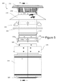
- FIG. 3 is a side view of the end cap assembly.
- FIG. 4 is a cross-sectional view along line 4 - 4 in FIG. 3 ;
- FIG. 5 is an exploded view of the end cap assembly
- FIG. 6 is a cross-sectional view along line 6 - 6 in FIG. 5 .
- FIG. 7 is a second side view of the end cap assembly.
- FIG. 8 is a partial, cross-sectional view along line 8 - 8 in FIG. 7 .
- FIG. 9 is a partial perspective view.
- FIG. 10 is a partial, perspective exploded view.
- FIG. 11 is a partial perspective view of the rigid pipe.
- the venting installation cap assembly finds use in a venting system having at least an outer wall and an inner exhaust tube.
- the assembly includes an exhaust cap having an exhaust path coupled to the inner exhaust tube defined by a pipe section.
- a planar support ring having an annulus through which the pipe section passes rests on the outer tube or an adapter to the outer tube.
- the ring annulus surrounds the pipe section and has a diameter greater than the diameter of the outer wall.
- the planar support ring includes a plurality of airflow regions, surrounds the exhaust path and provides a free flow of air between the outer wall and the inner exhaust tube.
- FIG. 1 depicts a relined chimney system 100 coupled an appliance or hearth 290 .
- the relined system may be comprised of single or double walled vent pipe comprising one or more pieces 145 , 200 passing through a ceiling 120 and roof 110 .
- the venting system 100 may be any single or double walled pipe to be provided through any combustibles such as ceiling insulation 125 , ceiling material 120 or roofing material 110 .
- the vent system terminates in a vent cap 180 on the exterior of a building.
- the vent system 100 and specifically piece 145 is sized to couple directly to the vent cap 180 .
- FIGS. 2-11 illustrates the present technology of a vent cap assembly 300 suitable for use with high-temperature relining systems.
- a venting cap 316 is mounted on a pipe 322 for relining an existing chimney installation with a rigid or flexible reliner is shown.
- a flexible reliner is illustrated.
- the vent cap assembly is illustrated herein in conjunction with an existing chimney structure ( 315 , 325 ) and relining material ( 320 ).
- a vent cap assembly 300 includes a cap 316 , storm collar 310 , pipe 322 , support ring 330 , support bracket 340 , centering bracket 335 , flex adapter 355 and adjustable ring 345 .
- Cap 316 includes a cylindrical wire mesh 316 a capped by plate 312 , the mesh 316 a forms a barrier through which exhaust 405 from an appliance or hearth 290 ( FIG. 4 ) are allowed to pass.
- a vent cap assembly 300 provides for exhaust from the appliance 290 while providing air flow through an annular region 400 between the outer chimney 315 and inner chimney 325 walls or between the liner 320 and the outer chimney wall if no inner chimney wall 325 is used.
- the vent cap assembly 300 is detailed further below. As illustrated in FIG. 2 , the vent cap assembly is provided on the exterior of a structure, such as the exterior of a roof 110 .
- outer chimney wall 315 and inner chimney wall 325 form a portion of an existing installation through which a relining vent tube 320 is routed.
- the vent tube 320 may be rigid, or flexible as illustrated. In one embodiment, no inner chimney wall 325 is utilized with the present technology.
- Internal vent tube 320 in one embodiment, comprises a flexible venting material comprising a heat and/or corrosive resistant material.
- Material which is suitable for use in such systems includes stainless steel.
- Commercial products suitable for use as vent material 320 include varieties of Type 304, 316, 441, 446, 447, 448, stainless steels. Very high temperature polymeric materials may also be used as the tube 320 in alternative embodiments.
- venting material 320 is snaked through the existing system or uses additional relining components, using the existing chimney as a chase until the lead end of the material reaches the end of the vent system near an existing vent cap.
- Vent material 320 is comprised of a vent material having a diameter or cross-section suitably sized to fit within all components of the inner wall 325 .
- vent material 320 is suitably sized to fit within all components of an existing wall such as outer wall 315 . In both such embodiments, air flow is allowed between the vent material 320 and the inner wall 325 or outer wall 315 . If air flow is possible between the appliance end and structure exterior end between the inner wall 315 and outer wall 325 , such flow should not be restricted.
- the inner chimney wall 325 and outer chimney wall 315 form an existing installation in a dwelling or other structure.
- An inner liner tube 320 is placed within the inner wall 325 .
- the flex adapter 355 engages and receives the flex tube 320 . It should be understood that the flex adapter 355 may be sized for various different sizes of internal chimney tubes 325 . A rigid pipe 322 engages the flex adapter 355 .
- a centering bracket 335 may be attached to the flex adapter 355 .
- Tabs 335 a on the centering bracket align the position of the flex adapter and flex tube within the inner wall 325 .
- An adjustable band 345 engages outer wall 315 of the existing chimney.
- Support ring 330 Resting on the adjustable band 345 is a support ring 330 .
- the support ring 330 may rest on the outer wall 315 directly.
- Support ring 330 includes an outer ring 332 , four spokes 334 (of which two- 334 a and 334 b —are illustrated) and four mesh areas 336 a - c (only three of which are illustrated) which allow air through from the annular region between walls 315 and 325 .
- An inner ring defines an annulus which allows the rigid pipe 322 therethrough.
- the mesh screens form a flow path from the region 400 between the inner wall 325 and the outer wall 315 and to the exterior of a building or structure through the gap between the storm collar 310 and the outer wall 315 .
- the storm collar includes a circumferential edge positioned a spaced distance apart from the outer wall forming a gap.
- Support ring 330 supports upper portions of the cap structure 300 .
- Support ring 330 is generally planar in that all of components 332 , 334 , 336 and the annulus lie in a single plane.
- the ring 330 may include a flange 331 ( FIG. 8 ).
- the mesh regions are integrally formed between the spokes 334 . Although four spokes and mesh regions are illustrated, one or more mesh regions and zero spokes may be utilized.
- a support bracket 340 is fastened by any suitable means to rigid tube 322 and rests on support ring 330 .
- Cap 316 including mesh region 316 a and top cap 312 engages pipe 322 , which engages adapter 355 and rests on support bracket 340 and ring 330 .
- the ring 330 is not fastened to the pipe 322 , but includes an annulus or hole through which the pipe 322 extends.
- the support bracket 340 sits on the disk, and on the top of the pre-existing chimney 315 / 315 and/or the band 345 , thereby providing structural support for the assembly.
- airflow 402 is provided through the mesh regions 336 for the region 400 , while exhaust for the appliance 404 exits through an exhaust flow path 404 formed by the flex tube 320 , rigid pipe 322 and mesh regions 316 a .
- Storm collar 310 is mounted to rigid pipe 322 and covers the flow path/mesh regions 336 . It should be understood that the technology does not require a double wall existing chimney, and would be useful in installations where no inner wall 325 is present.
Landscapes
- Engineering & Computer Science (AREA)
- Chemical & Material Sciences (AREA)
- Combustion & Propulsion (AREA)
- Mechanical Engineering (AREA)
- General Engineering & Computer Science (AREA)
- Ventilation (AREA)
Abstract
Description
Claims (19)
Priority Applications (1)
| Application Number | Priority Date | Filing Date | Title |
|---|---|---|---|
| US13/789,074 US9765963B2 (en) | 2013-03-07 | 2013-03-07 | Vent cap for chimney relining system |
Applications Claiming Priority (1)
| Application Number | Priority Date | Filing Date | Title |
|---|---|---|---|
| US13/789,074 US9765963B2 (en) | 2013-03-07 | 2013-03-07 | Vent cap for chimney relining system |
Publications (2)
| Publication Number | Publication Date |
|---|---|
| US20140256242A1 US20140256242A1 (en) | 2014-09-11 |
| US9765963B2 true US9765963B2 (en) | 2017-09-19 |
Family
ID=51488379
Family Applications (1)
| Application Number | Title | Priority Date | Filing Date |
|---|---|---|---|
| US13/789,074 Active 2036-04-21 US9765963B2 (en) | 2013-03-07 | 2013-03-07 | Vent cap for chimney relining system |
Country Status (1)
| Country | Link |
|---|---|
| US (1) | US9765963B2 (en) |
Families Citing this family (2)
| Publication number | Priority date | Publication date | Assignee | Title |
|---|---|---|---|---|
| USD748472S1 (en) | 2013-11-08 | 2016-02-02 | W.L. Gore & Associates Gmbh | Vent |
| USD984627S1 (en) * | 2023-01-17 | 2023-04-25 | Wei Huang | Exhaust fan |
Citations (2)
| Publication number | Priority date | Publication date | Assignee | Title |
|---|---|---|---|---|
| US1328647A (en) * | 1917-03-13 | 1920-01-20 | Carl Reinhold Adolph | Combination-flue |
| US20040142652A1 (en) * | 2003-01-21 | 2004-07-22 | Hediger Elvin D. | Liner adaptor for chimneys |
-
2013
- 2013-03-07 US US13/789,074 patent/US9765963B2/en active Active
Patent Citations (2)
| Publication number | Priority date | Publication date | Assignee | Title |
|---|---|---|---|---|
| US1328647A (en) * | 1917-03-13 | 1920-01-20 | Carl Reinhold Adolph | Combination-flue |
| US20040142652A1 (en) * | 2003-01-21 | 2004-07-22 | Hediger Elvin D. | Liner adaptor for chimneys |
Also Published As
| Publication number | Publication date |
|---|---|
| US20140256242A1 (en) | 2014-09-11 |
Similar Documents
| Publication | Publication Date | Title |
|---|---|---|
| US8408196B2 (en) | Ceiling support box with outside air inlet | |
| US20070221195A1 (en) | Coupling for direct venting system | |
| EP2469166A1 (en) | Combined system for flue gas removal, air supply and ventilation air removal | |
| CA2077126C (en) | High efficiency induced draft condensing furnace with horizontal plastic vent termination assembly | |
| US9765963B2 (en) | Vent cap for chimney relining system | |
| US8056552B2 (en) | Wall thimble with outside air inlet | |
| US9140450B2 (en) | Retrofitted corrosive resistant venting system | |
| US4893608A (en) | Furnace roof jack with pivoting flashing plate | |
| US11236944B2 (en) | Method and system for furnace sealing | |
| US20100089382A1 (en) | Bicentric direct vent terminal | |
| US8230849B2 (en) | Wall thimble with outside air inlet | |
| US20140209087A1 (en) | Dual category venting system | |
| EP2946144B1 (en) | Mounting structure comprising a flue pipe mounting apparatus | |
| US7766731B2 (en) | Exhaust gas chimney | |
| KR200473890Y1 (en) | Dual exhaust pipe | |
| US20070256682A1 (en) | Gasket-less vent pipe coupling | |
| US3399617A (en) | Gas exhaust ventilator | |
| BE1024629A1 (en) | COMBINATION AIR SUPPLY-COMBUSTION GAS EXHAUST SYSTEM FOR GAS FIREPLACES | |
| KR101994965B1 (en) | Chimney stack pipe having supporting portion and assembling method thereof | |
| JP2010054112A (en) | Connecting section structure of exhaust tube | |
| US20060249142A1 (en) | Pipe coupling for a venting system | |
| JP2016188747A (en) | Connection structure of chimney | |
| FI12202U1 (en) | Supply channel, installation kit for an exhaust air device, and exhaust air device | |
| CN210688435U (en) | Warmer with multi-angle air outlet | |
| CN207081437U (en) | A kind of condensation-proof that can be stretched up and down pours in down a chimney instrument exhaust hood |
Legal Events
| Date | Code | Title | Description |
|---|---|---|---|
| AS | Assignment |
Owner name: M&G DURAVENT, INC., CALIFORNIA Free format text: ASSIGNMENT OF ASSIGNORS INTEREST;ASSIGNORS:BERTLER, MATTHEW L.;DEVINE, RYAN L.;PETTITT, ERIK;REEL/FRAME:030264/0635 Effective date: 20130412 |
|
| STCF | Information on status: patent grant |
Free format text: PATENTED CASE |
|
| CC | Certificate of correction | ||
| AS | Assignment |
Owner name: DURAVENT, INC., MICHIGAN Free format text: CHANGE OF NAME;ASSIGNOR:M&G DURAVENT, INC.;REEL/FRAME:046136/0642 Effective date: 20180330 |
|
| MAFP | Maintenance fee payment |
Free format text: PAYMENT OF MAINTENANCE FEE, 4TH YEAR, LARGE ENTITY (ORIGINAL EVENT CODE: M1551); ENTITY STATUS OF PATENT OWNER: LARGE ENTITY Year of fee payment: 4 |
|
| AS | Assignment |
Owner name: JPMORGAN CHASE BANK, N.A., AS ADMINISTRATIVE AGENT, ILLINOIS Free format text: SECURITY INTEREST;ASSIGNOR:DURAVENT, INC.;REEL/FRAME:058258/0586 Effective date: 20210930 |
|
| MAFP | Maintenance fee payment |
Free format text: PAYMENT OF MAINTENANCE FEE, 8TH YEAR, LARGE ENTITY (ORIGINAL EVENT CODE: M1552); ENTITY STATUS OF PATENT OWNER: LARGE ENTITY Year of fee payment: 8 |