US9749006B1 - Estimation and mitigation of swept-tone interferers in frequency-hopped systems - Google Patents
Estimation and mitigation of swept-tone interferers in frequency-hopped systems Download PDFInfo
- Publication number
- US9749006B1 US9749006B1 US15/374,285 US201615374285A US9749006B1 US 9749006 B1 US9749006 B1 US 9749006B1 US 201615374285 A US201615374285 A US 201615374285A US 9749006 B1 US9749006 B1 US 9749006B1
- Authority
- US
- United States
- Prior art keywords
- phase
- swept
- estimates
- signal
- frequency
- Prior art date
- Legal status (The legal status is an assumption and is not a legal conclusion. Google has not performed a legal analysis and makes no representation as to the accuracy of the status listed.)
- Active
Links
- 230000000116 mitigating effect Effects 0.000 title abstract description 22
- 239000002131 composite material Substances 0.000 claims abstract description 61
- 235000008694 Humulus lupulus Nutrition 0.000 claims description 66
- 238000000034 method Methods 0.000 claims description 36
- 238000001228 spectrum Methods 0.000 claims description 10
- 239000013598 vector Substances 0.000 claims description 8
- 238000001514 detection method Methods 0.000 claims description 6
- 230000003750 conditioning effect Effects 0.000 claims description 4
- 238000005070 sampling Methods 0.000 claims description 4
- 230000002452 interceptive effect Effects 0.000 abstract description 7
- 230000000737 periodic effect Effects 0.000 abstract description 6
- 238000004891 communication Methods 0.000 description 11
- 238000010586 diagram Methods 0.000 description 9
- 230000006870 function Effects 0.000 description 7
- 230000001934 delay Effects 0.000 description 6
- 230000002596 correlated effect Effects 0.000 description 4
- 230000000875 corresponding effect Effects 0.000 description 4
- 238000012935 Averaging Methods 0.000 description 3
- 230000003044 adaptive effect Effects 0.000 description 3
- 238000013459 approach Methods 0.000 description 3
- 230000005540 biological transmission Effects 0.000 description 3
- 238000012986 modification Methods 0.000 description 2
- 230000004048 modification Effects 0.000 description 2
- 230000003287 optical effect Effects 0.000 description 2
- 238000012545 processing Methods 0.000 description 2
- 238000000926 separation method Methods 0.000 description 2
- 230000007704 transition Effects 0.000 description 2
- 238000007792 addition Methods 0.000 description 1
- 239000000654 additive Substances 0.000 description 1
- 230000000996 additive effect Effects 0.000 description 1
- 238000005267 amalgamation Methods 0.000 description 1
- 238000003491 array Methods 0.000 description 1
- 238000004590 computer program Methods 0.000 description 1
- 230000007423 decrease Effects 0.000 description 1
- 238000013461 design Methods 0.000 description 1
- 230000001747 exhibiting effect Effects 0.000 description 1
- 238000001914 filtration Methods 0.000 description 1
- 238000009434 installation Methods 0.000 description 1
- 238000012886 linear function Methods 0.000 description 1
- 238000005192 partition Methods 0.000 description 1
- 230000008569 process Effects 0.000 description 1
Images


Classifications
-
- H—ELECTRICITY
- H04—ELECTRIC COMMUNICATION TECHNIQUE
- H04B—TRANSMISSION
- H04B1/00—Details of transmission systems, not covered by a single one of groups H04B3/00 - H04B13/00; Details of transmission systems not characterised by the medium used for transmission
- H04B1/06—Receivers
- H04B1/10—Means associated with receiver for limiting or suppressing noise or interference
-
- H—ELECTRICITY
- H04—ELECTRIC COMMUNICATION TECHNIQUE
- H04B—TRANSMISSION
- H04B1/00—Details of transmission systems, not covered by a single one of groups H04B3/00 - H04B13/00; Details of transmission systems not characterised by the medium used for transmission
- H04B1/69—Spread spectrum techniques
- H04B1/713—Spread spectrum techniques using frequency hopping
- H04B1/715—Interference-related aspects
-
- H—ELECTRICITY
- H04—ELECTRIC COMMUNICATION TECHNIQUE
- H04L—TRANSMISSION OF DIGITAL INFORMATION, e.g. TELEGRAPHIC COMMUNICATION
- H04L25/00—Baseband systems
- H04L25/02—Details ; arrangements for supplying electrical power along data transmission lines
- H04L25/03—Shaping networks in transmitter or receiver, e.g. adaptive shaping networks
- H04L25/03828—Arrangements for spectral shaping; Arrangements for providing signals with specified spectral properties
- H04L25/03834—Arrangements for spectral shaping; Arrangements for providing signals with specified spectral properties using pulse shaping
- H04L25/03853—Shaping by digital methods other than look up tables or up/down converters
-
- H—ELECTRICITY
- H04—ELECTRIC COMMUNICATION TECHNIQUE
- H04B—TRANSMISSION
- H04B1/00—Details of transmission systems, not covered by a single one of groups H04B3/00 - H04B13/00; Details of transmission systems not characterised by the medium used for transmission
- H04B1/69—Spread spectrum techniques
- H04B1/713—Spread spectrum techniques using frequency hopping
- H04B1/715—Interference-related aspects
- H04B2001/7152—Interference-related aspects with means for suppressing interference
-
- H—ELECTRICITY
- H04—ELECTRIC COMMUNICATION TECHNIQUE
- H04B—TRANSMISSION
- H04B2201/00—Indexing scheme relating to details of transmission systems not covered by a single group of H04B3/00 - H04B13/00
- H04B2201/69—Orthogonal indexing scheme relating to spread spectrum techniques in general
- H04B2201/713—Frequency hopping
- H04B2201/71353—Fast frequency hopping
Definitions
- the present invention relates to wireless communication systems, including those that are frequency-hopped, that are subject to interference, and in particular, the estimation and mitigation of swept-tone interferers that are routinely employed as jamming signals.
- Swept-tone interferers are usually characterized by linear frequency modulations: the instantaneous frequency of the signal sweeps a range of several megahertz (MHz) in a few microseconds, thereby affecting the entire band targeted by the interfering signal.
- MHz megahertz
- the fast variations of the instantaneous frequency of swept-tone jammers make the design of estimation and mitigation techniques particularly challenging.
- some embodiments of the present invention estimate the period of the swept-tone interferer and models it, in the observation bandwidth, as a magnitude-periodic signal with a common pulse shape. Each periodic segment of the interfering signal may be different from any other segment in phase.
- the magnitude-periodic model is over the hop bandwidth of a frequency-hopped system.
- the model is over all the hops of a frequency-hopped system that are affected by the swept-tone interferer. The interference estimate may be subtracted from the received filtered composite signal to generate an interference-mitigated signal of interest.
- a method for estimating a swept-tone interferer comprises: receiving a composite signal over an observation bandwidth, wherein the composite signal comprises a signal of interest and the swept-tone interferer; modeling the swept-tone interferer over the observation bandwidth as a magnitude-periodic signal, wherein the magnitude-periodic signal comprises a plurality of phase-rotated pulses, and wherein each of the plurality of phase-rotated pulses comprises a common pulse shape and a distinct phase rotation; generating an energy signal based on the composite signal; estimating a period of the magnitude-periodic signal based on the energy signal; generating an initial estimate of the common pulse shape based on the period and energy detection of the composite signal, wherein a length of the initial estimate of the common pulse shape is equal to the period; generating a plurality of phase estimates based on a plurality of epochs and the initial estimate of
- the frequency-hopping system comprises a plurality of hops, each of the plurality of hops comprising each of a plurality of hop bandwidths
- a method for estimating a swept-tone interferer in a frequency-hopping system comprises: sampling a composite signal over each of the plurality of hop bandwidths to generate an initial set of samples for each of the plurality of hops, wherein the composite signal comprises a signal of interest and the swept-tone interferer, and wherein each of the initial set of samples comprises a first set of samples and a second set of samples; determining a number of the first set of samples for each of the plurality of hops; truncating the first set of samples from the initial set of samples for each of the plurality of hops; concatenating the truncated set of samples for each of the plurality of hops to generate a reconstructed composite signal; modeling the swept
- FIGS. 1A and 1B are plots of the instantaneous frequency of swept-tone interferers that can be estimated and mitigated by embodiments of the present invention.
- FIGS. 2A and 2B are plots of the instantaneous frequency of swept-tone interferers in a frequency-hopping wireless communication system that can be estimated by embodiments of the present invention.
- FIG. 3 is a more detailed view of the time-series of the instantaneous frequency of swept-tone interferers in a frequency-hopping wireless communication system.
- FIGS. 4A, 4B and 4C are time-series plots of a swept-tone interferer at different stages in an embodiment of the present invention.
- FIG. 5 is an embodiment of a magnitude-periodic signal that enables estimation and mitigation of a swept-tone interferer, according to some embodiments of the present invention.
- FIG. 6 is a block diagram of an embodiment for estimation and mitigation of a swept-tone interferer, according to an embodiment of the present invention.
- FIG. 7 is a block diagram for a method for estimation of a swept-tone interferer in a frequency-hopping wireless communication system, according to an embodiment of the present invention.
- FIGS. 8A and 8B are block diagrams of another embodiment for estimation and mitigation of a swept-tone interferer, according to the present invention.
- FIG. 9 is a flow chart for a method for estimation and mitigation of a swept-tone interferer, according to an embodiment of the present invention.
- FIG. 10 is a flowchart for a method for estimation of a swept-tone interferer in a frequency-hopped system, according to another embodiment of the present invention.
- FIG. 11 is a flowchart for a method for estimation of a swept-tone interferer in a frequency-hopped system, according to yet another embodiment of the present invention.
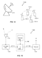
- FIG. 12 is a block diagram of a system comprising the means for estimation and mitigation of a swept-tone interferer according to an embodiment of the present invention.
- FIG. 13 is a block diagram of another system comprising the means for estimation and mitigation of a swept-tone interferer according to another embodiment of the present invention.
- the present invention is well-suited for the estimation and mitigation of swept-tone interferers, i.e. jamming signals that are frequency-modulated with a fast varying center frequency.
- swept-tone interferers i.e. jamming signals that are frequency-modulated with a fast varying center frequency.
- the time-frequency evolution, or instantaneous frequency as function of time, for representative swept-tone interferers are shown in FIGS. 1A and 1B , wherein the interfering signal sweeps from a frequency f start to a frequency f stop over a few microseconds, and the system that is being affected by this interfering signal operates over an observation bandwidth, denoted [W start , W stop ].
- the instantaneous frequency is a linear function, which may be specified as:
- the observation bandwidth lies entirely within the sweep-range of the interferer
- FIG. 1B illustrates the sweep-range of the interferer originating within the observation bandwidth and ending outside the observation bandwidth.
- embodiments of the present invention are able to successfully estimate and mitigate a swept-tone interferer as long as its sweep-range crosses either edge of the observation bandwidth, which may be represented by the conditions f start ⁇ W start ⁇ f stop and f start ⁇ W stop ⁇ f stop . That is, the observation bandwidth may lie entirely within the sweep-range, or the sweep-range may start or stop within the observation bandwidth.
- Embodiments of the present invention are also well-suited for the estimation and mitigation of swept-tone interferers in representative frequency-hopped systems, shown in FIGS. 2A and 2B .
- the swept-tone interferer sweeps from a start frequency (f start ) to a stop frequency (f stop ), and interferes with each of the hops of the frequency-hopping wireless communications system.
- the center-frequency hopping sequence that is employed is ⁇ f i ⁇ 2 , f i , f i+1 , f i+2 ⁇ , and the swept-tone interferer disrupts communications in each of the frequency hops in the order of the frequency-hopping sequence.
- the swept-tone interferer shown in FIG. 2A has a repetition rate that results in the interferer crossing each of the frequency hops a certain number of times.
- the swept-tone interferer shown in FIG. 2B has a higher repetition rate, which results in the interferer crossing each of the frequency hops an even greater number of times compared to the case shown in FIG. 2A .
- the swept-tone may not interfere with every hop, but embodiments of the present invention described herein may be implemented in those frequency hops that have been affected by the interferer.
- FIG. 3 plots a “zoomed-in” time-series of the instantaneous frequency of swept-tone interferers in a frequency-hopping wireless communication system, wherein the first hop 311 is at center frequency f 0 and the second hop 313 is at center frequency f 2 .
- the swept-tone interferer is defined by the sweep-rate and the period 319 (denoted T), and the repetition rate of the swept-tone interferer is defined as the inverse of the period.
- the representative linear swept-tone interferers shown in FIGS. 1, 2A-2B , and 3 continually sweep from a start frequency (f start ) to a stop frequency (f stop ), and it is start, assumed that the transition from f stop to f start can be instantaneous in time.
- the transition from f stop to f start may be a linear sweep as well, in which case the interferer is denoted as exhibiting a “linear triangular sweep.”
- the swept-tone interferer enters the frequency band of the first hop 311 at a first delay 317 (denoted ⁇ 1 ) relative to the start of the hop at time t 0 .
- the interferer continues to sweep through the hop for the duration of the hop 323 (denoted T hop ), and enters the second hop 313 at a second delay 321 (denoted ⁇ 2 ) relative to the start of the hop at time (t 0 +T hop ).
- the length of the first and second delays, as well as the number of times the linear swept-tone interferer sweeps through a particular hop is a function of the start frequency (f start ), the stop frequency (f stop ), the sweep-rate (denoted ⁇ ) and the period (T) of the swept-tone interferer. Determining the delay for a particular frequency hop enables the identification of those samples in that frequency hop that have been affected by the swept-tone interferer. Thus, the determination of the delays for each frequency hop affected by the interferer can be used to generate an estimate of the interferer.
- the delay for the next frequency hop( ⁇ i+1 ) in the case of a linear swept-tone interferer, can be determined using:
- ⁇ i + 1 ( ⁇ i + T hop + ⁇ ⁇ ⁇ f ⁇ ) ⁇ % ⁇ T .
- Equation (4) The relative delay due to the frequency separation ⁇ f and the sweep rate ⁇ may be denoted ⁇ .
- ⁇ ⁇ f/ ⁇ shown in Equation (4) is valid for swept-tone interferers with linear sweeps.
- the delay for any other frequency hop can be estimated by cross-correlating the samples of the first frequency hop and the samples of the other frequency hop.
- the samples for each frequency hop include a first set of samples that correspond to a period of time prior to the interferer entering that frequency hop, and a second set of samples that correspond to the frequency hop being affected by the swept-tone interferer.
- cross-correlating the samples from the two frequency hops will have a first correlation peak at a lag value that equals ( ⁇ i ⁇ j ).
- the delay for other frequency hops can be estimated by cross-correlating the samples of the first frequency hop and the samples for multiple other frequency hops.
- the samples for the first frequency hop may be correlated with the samples for the second and third frequency hops, and subsequently with the samples for both the third and fourth frequency hops.
- the first peaks of the correlation outputs may provide coarse delay values. This may be followed by a fine search around the coarse delay values to maximize a sum correlation score.
- Other embodiments may rely on the cross-correlations between sets of samples from different combinations of multiple frequency hops to provide the coarse delay values.
- FIGS. 4A-4C are generated upon sampling the composite signal (comprising the signal of interest and the swept-tone interferer) over the observation bandwidth.
- the power of the swept-tone interferer is significantly greater than that of the signal of interest.
- FIG. 4A shows the real component of the complex-valued swept-tone interferer over the observation bandwidth.
- the instantaneous frequency decreases (approaching its lowest frequency at ⁇ 1.39) and then increases as a function of time, which is characteristic of a swept-tone interferer.
- FIG. 4B shows the real component of the swept-tone interferer after a low-pass filtering operation.
- the low-pass filter has a bandwidth that is equal to or less than the observation bandwidth.
- the magnitude-square of the complex-valued filtered composite signal is shown in FIG. 4C .
- the waveform shown in FIG. 4C is a periodic signal, termed a “magnitude-periodic signal,” and serves as the basis of the model used for the estimation and mitigation of swept-tone interferers, as described in embodiments of the present invention.
- a period of the magnitude-periodic signal, as shown in FIG. 4C is called an epoch.
- the magnitude-periodic signal may be construed as comprising multiple non-overlapping, contiguous epochs.
- FIG. 5 depicts another model of a magnitude-periodic signal that is used to enable the estimation of the swept-tone interferer.
- the epochs of the magnitude-periodic signal are denoted v 0 , v 1 , . . . , v K .
- the magnitude-periodic signal may be represented as
- FIG. 6 is a block diagram 600 of an embodiment for estimation and mitigation of a swept-tone interferer, according to the present invention.
- This system includes some features and/or components that are similar to those shown in FIGS. 4 and 5 , and described above. At least some of these features and/or components may not be separately described in this section.
- a composite signal comprising a signal of interest s and a swept-tone interferer J is received and filtered using a low-pass filter 605 .
- the low-pass filtered swept-tone interferer comprises non-overlapping, contiguous epochs, wherein each epoch comprises a common pulse shape p(t) and a distinct phase rotation ⁇ k .
- the filtered composite signal is used by a period estimation module 615 to determine the period T of the swept-tone interferer, which is also the length of the epoch.
- the period T and the filtered composite signal are then utilized by an initial pulse estimation module 635 to generate an initial estimate p 0 (t) of the common pulse shape p(t).
- the final pulse estimation module 675 generates a final estimate of the common pulse shape ⁇ circumflex over (p) ⁇ (t) based on the initial pulse estimate and the set of distinct phase rotations.
- This final pulse estimate of the common pulse shape, and the set of distinct phase rotations is used by an interference estimate module 695 to generate an estimate of the swept-tone interferer.
- Summer 625 is used to subtract the estimate of the swept-tone interferer from the filtered composite signal to generate an interference-mitigated signal of interest.
- FIG. 7 is a block diagram of an embodiment for estimation of a swept-tone interferer in a frequency-hopping wireless communication system, according to the present invention.
- This system includes some features and/or components that are similar to those shown in FIGS. 4-6 , and described above. At least some of these features and/or components may not be separately described in this section.
- the embodiment shown in FIG. 7 is configured to operate in a frequency-hopped system, and receives a composite signal that comprises the signal of interest and a swept-tone interferer over each of the frequency hops.
- a bank of low-pass filters 705 is initially employed to filter over each of the hop bandwidths. That is, for each of the frequency hops, the observation bandwidth corresponds to the hop bandwidth for that frequency hop.
- the hop bandwidths for all the frequency hops are equal. In other embodiments, the hop bandwidths may be distinct for one or more frequency hops.
- the filtered composite signals for each of the frequency hops are processed by a delay estimation module 707 that determines the delay for each set of samples.
- the delays for each of the frequency hops may be determined using Equation (4) if the swept-tone parameters (for an interferer with a linear sweep) are known. That is, if the repetition rate, start and stop frequencies and sweep rate of the swept-tone interferer are known, the delays ⁇ 0 , ⁇ 1 , . . . ⁇ may be computed as described earlier.
- the set of samples corresponding to the first frequency hop of the packet/transmission may be used to compute an energy signal, and energy detection of that energy signal may be employed to determine the delay ( ⁇ 0 ) for the first frequency hop. Delays for other frequency hops can be determined by cross-correlating the samples corresponding to the first frequency hop and the samples corresponding to another frequency hop, as described in the context of FIG. 3
- the delays for each of the frequency hops are used by the signal conditioning module 709 to reconstruct the composite signal from sets of samples from each of the frequency hops. That is, the delay of a frequency hop corresponds to the number of the first set of samples prior to the interferer entering that particular frequency hop.
- the signal conditioning module 709 truncates the first set of samples from each set of samples for each frequency hop, and then concatenates the remaining (or second) set of samples from each frequency hop to generate a reconstructed composite signal.
- the second set of samples contains signal of interest samples that are subject to interference, and concatenating them reconstructs the composite signal.
- the signal conditioning module 709 may be used in the context of FIG. 2A , where there is a relatively lower number of passes of the interferer through each of the frequency hops. That is, if the ratio of the length of the frequency hop (T hop ) to the period of the swept-tone interferer (T) is small, then the energy from each of the frequency hops must be combined to generate a reliable estimate of the swept-tone interferer. Thus, the first samples from each frequency hop, which correspond to samples that are not affected by the interferer, must be truncated prior to combining the samples from all the frequency hops.
- the swept-tone interferer may be modeled as a magnitude-periodic signal, as discussed previously.
- the pulse and phase estimation module 760 may be an amalgamation of the phase estimation module 655 with the final pulse estimation module 675 , shown in FIG. 6 .
- an alternative structure or method may be used to generate the plurality of phase estimates and the final estimate of the common pulse shape.
- FIG. 8A is a block diagram 800 of an embodiment for estimation and mitigation of a swept-tone interferer, according to the present invention.
- This system includes some features and/or components that are similar to those shown in FIGS. 4, 5 and 6 , and described above. At least some of these features and/or components may not be separately described in this section.
- the magnitude-square of the filtered composite signal (also referred to as an energy signal) is computed using a squaring module 812 , and serves as an input to a fast Fourier transform (FFT) block 814 and an energy detector 818 .
- the FFT block 814 computes a frequency spectrum of the energy signal, and the period estimator 816 uses at least one harmonic of the frequency spectrum to estimate the period T of the energy signal.
- the initial estimate of the common pulse shape p 0 (t) is generated using a pulse generator 822 , and is based on the period T and the output of the energy detector 818 .
- the estimated phases are used by a unit vector generator 828 to generate phase vectors with unit magnitudes and phases that are based on the estimated distinct phase rotations.
- An averaging unit 834 generates a final estimate of the common pulse shape ⁇ circumflex over (p) ⁇ (t) by averaging the de-rotated epochs, i.e.
- each of the epochs comprises a distinct amplitude (as described in Equation (8)); the amplitude for the k th epoch may be estimated as
- a ⁇ k ⁇ ⁇ v 0 , v k ⁇ ⁇ ⁇ v 0 ⁇ 2 , Eq ⁇ ⁇ ( 11 ) and the corresponding final estimate of the common pulse shape is computed as
- Equation (12) simplifies to the final estimate of the common pulse shape in Equation (10) when all the amplitudes are equal to each other.
- Demultiplexer 836 generates K+1 copies of the final estimate of the common pulse shape, each of which is multiplied by a unit vector with a phase equal to the respective estimated distinct phase rotation using a second bank of K+1 multipliers 838 . 0 , . . . , 838 .K.
- the distinctly rotated final pulse estimates are concatenated using a multiplexer 842 to generate an estimate of the swept-tone interferer, given by
- this estimate may be subtracted from the filtered complex-valued composite signal to generate an interference-mitigated signal of interest.
- FIG. 8B is a block diagram 800 that maps the embodiment for estimation of a swept-tone interferer described in FIG. 8A to the generic modules shown in FIG. 6 .
- This system includes some features and/or components that are similar to those shown in FIGS. 4, 5, 6 and 8A , and described above. At least some of these features and/or components may not be separately described in this section.
- the period estimation module 815 is realized by using at least one harmonic of a frequency spectrum to determine the period, and the frequency spectrum is generated by computing the FFT of an energy signal that is based on the filtered composite signal.
- computing the autocorrelation of the magnitude-periodic signal may be used to determine the period.
- the autocorrelation will exhibit peaks at all lags that comprise the alignment of the common pulse shapes. That is, a maximum peak of the autocorrelation will occur at zero-lag and additional peaks will occur at lags that correspond to the period of the magnitude-periodic signal.
- both time- and frequency-domain methods may be employed to determine the period in the period estimation module 815 .
- the initial pulse estimation module 835 is realized using an energy detector and a pulse generator that generates an initial estimate of the common pulse shape by extracting the first epoch of the swept-tone interferer.
- the energy detector processes the energy signal to determine the start and end points of the common pulse shape in the first epoch, and the period is then used to extract the first epoch.
- the autocorrelation of the magnitude-periodic signal may be used to determine the initial pulse estimate. For example, a segment that begins at a minimum value of the autocorrelation, and extends for the length of a period, may be used as the initial estimate of the common pulse shape.
- the initial pulse estimate may be correlated with each of the epochs in an effort to verify that a robust estimate of the common pulse shape has been extracted (as compared to a spurious feature with a comparable amount of energy) prior to the estimation of the distinct phase rotations.
- normalized correlation values between 0.85 and 1.0 are expected if a “correct” epoch has been extracted as the initial pulse estimate.
- the phase estimation module 855 is realized using a bank of correlators that correlate each of the epochs with the initial pulse estimate. As described in reference to FIG. 8A , the final pulse estimation module 875 averages all K+1 de-rotated epochs to generate the final pulse estimate. Finally, the interference estimation module 895 generates an estimate of the interference by concatenating replicas of the final pulse estimate after they have been rotated by the respective estimate of the distinct phase rotation.
- FIG. 9 is a flowchart for a method for estimating a swept-tone interferer, according to an embodiment of the present invention.
- the order of steps in the flowchart may be changed.
- some of the steps in the flowchart may be skipped or additional steps may be added.
- the method 900 begins at step 910 where a composite signal comprising the signal of interest and a swept-tone interferer is received.
- the composite signal further comprises additive white Gaussian noise (AWGN).
- AWGN additive white Gaussian noise
- the composite signal may further comprise other modeled interference.
- the composite signal is received (and sampled) over an observation bandwidth, and subsequently filtered using a low-pass filter.
- the low-pass filter may have a bandwidth that is less than or equal to the observation bandwidth, and in other embodiments, multiple low-pass filters may be employed for this purpose.
- the swept-tone interferer over the observation bandwidth is modeled as a magnitude-periodic signal comprising a set of non-overlapping, contiguous phase-rotated pulses.
- each of the phase-rotated pulses comprises a common pulse shape and a distinct phase rotation.
- the phase-rotated pulses further comprise distinct amplitudes.
- an energy signal is computed based on the composite signal using a magnitude-squaring function.
- the energy signal is a periodic signal, and may be segmented into epochs, each of which comprises at least the common pulse shape.
- the period of the magnitude-periodic signal is estimated based on at least one harmonic of a frequency spectrum of the energy signal.
- the fast Fourier transform FFT
- the period is based on only the strongest (and typically fundamental) harmonic of the frequency spectrum.
- multiple harmonics are used to estimate the period, via an average or a weighted average.
- an initial estimate of the common pulse shape is generated based on the period and the energy detection of the energy signal.
- an energy detector is used to determine the start and end (in time) of the common pulse shape and knowledge of the period enables the generation of an initial estimate of the common pulse shape.
- the first epoch may be used as an initial estimate of the common pulse shape.
- the set of distinct phase rotations is estimated based on a plurality of epochs and the initial estimate of the common pulse shape.
- the epochs are non-overlapping, contiguous segments of the filtered composite signal, wherein each epoch comprises a common pulse shape and a distinct phase rotation (which is being estimated at this step).
- the initial estimate of the common pulse shape is correlated with each of the plurality of epochs to generate the distinct phase rotation estimate.
- a plurality of phase de-rotated pulse estimates are generated by multiplying each of the epochs by a unit vector that has a phase that is equal to the negative of the estimated distinct phase rotation for that epoch.
- the k th pulse estimate is given by ⁇ k v k (t) exp( ⁇ j ⁇ circumflex over ( ⁇ ) ⁇ k ).
- a weighted average of the plurality of phase de-rotated pulse estimates is computed to generate a final estimate of the common pulse shape.
- the final estimate of the common pulse shape of the swept-tone interferer will be minimally affected by AWGN and the signal of interest due to the averaging of all the epochs.
- the final estimate of the common pulse shape is rotated by each of the distinct phase rotations, and the rotated final estimates are concatenated to generate an estimate of the swept-tone interference.
- the estimate of the swept-tone interference is subtracted from the filtered composite signal to generate an interference-mitigated signal of interest.
- FIG. 10 is a flowchart for a method for estimation of a swept-tone interferer in a frequency-hopped system, according to another embodiment of the present invention.
- the order of steps in the flowchart may be changed.
- some of the steps in the flowchart may be skipped or additional steps may be added.
- This flowchart includes some steps that are similar to those shown in FIG. 9 and described above. At least some of these steps may not be separately described in this section.
- the method 1000 begins at step 1010 where a composite signal, comprising the signal-of-interest and the swept-tone interferer, is sampled for each of the frequency hops of a frequency-hopped system.
- a composite signal comprising the signal-of-interest and the swept-tone interferer
- the interferer sweeps through the frequency band of each hop a certain number of times.
- the number of sweeps through any one frequency band is not enough to enable modeling the swept-tone interferer as a magnitude-periodic signal.
- the samples from each of the frequency hops are combined to more reliably estimate the interferer.
- the composite signal is first processed through a bank of low-pass filters, where the passband of each of the low-pass filters corresponds to the frequency band for each of the frequency hops of the frequency-hopped system. That is, the center frequency of each of the low-pass filters in the filter bank corresponds to the center frequency of the frequency band for each of the frequency hops.
- each initial set of samples comprises a first set of samples, in which the interferer has not yet entered the frequency band of that frequency hop, and a second set of samples, which are affected by the swept-tone interferer.
- the number of samples in the first set of samples for each initial set of samples is determined. This determination may be based on parameters of the swept-tone interferer, if they are known, or by energy detection on the initial samples of the first hop followed by cross-correlating the initial samples of the first hop with the initial samples of every other frequency hop. That is, the delay for each frequency hop is determined.
- the first set of samples is truncated.
- the second set of samples for each frequency hop is concatenated, in the order of the frequency-hopping sequence, to generate a reconstructed composite signal.
- the reconstructed composite signal having been combined over all frequency hops, now contains a far greater number of sweeps of the interferer, and enables modeling the interferer as a magnitude-period signal, which is performed at step 1020 .
- the modeling is similar to that described in step 920 in FIG. 9 .
- the period of the magnitude-periodic signal is estimated.
- the period may be estimated as the inverse of the repetition rate. If the parameters are unknown, the method according to steps 930 and 940 in FIG. 9 may be employed to estimate the period. Steps 1040 - 1090 are similar to steps 940 - 990 in FIG. 9 .
- FIG. 11 is a flowchart for a method for estimation of a swept-tone interferer in a frequency-hopped system, according to yet another embodiment of the present invention.
- the order of steps in the flowchart may be changed.
- some of the steps in the flowchart may be skipped or additional steps may be added.
- This flowchart includes some steps that are similar to those shown in FIGS. 9 and 10 and described above. At least some of these steps may not be separately described in this section.
- the method 1100 begins at step 1110 where a composite signal, comprising the signal-of-interest and the swept-tone interferer, is sampled for each of the frequency hops of a frequency-hopped system.
- the interferer sweeps through the frequency band of each hop a number of times that is greater than that described in FIG. 2A . That is, the number of sweeps through any one frequency band is enough to enable modeling the swept-tone interferer as a magnitude-periodic signal.
- the samples from each of the frequency hops are processed independently and on a per frequency hop basis.
- steps 1120 through 1190 are performed for each of the N hops of a frequency-hopped system. They are functionally similar to steps 920 through 990 as shown in FIG. 9 and described above.
- FIG. 12 depicts a system 1200 comprising means for estimation and mitigation of a swept-tone interferer according an embodiment of the present invention.
- This system includes some features and/or components that are similar to those shown in FIGS. 4 and 8 and described above. At least some of these features and/or components may not be separately described in this section.
- the system 1200 comprises member nodes 1220 - 1 . . . 1220 - 4 of a wireless network and a nearby radar installation 1210 .
- the communication of the network nodes may be subject to interference due to the radar sweep signals, whose power is typically significantly higher than the power of the inter-node communications.
- the radar sweep signal acts as a swept-tone interferer that can be estimated and mitigation by embodiments of the present invention.
- each of the network nodes 1220 - 1 . . . 1220 - 4 may be configured as the system 1300 shown in FIG. 13 , wherein an antenna 1310 receives both the signal of interests and the interfering radar sweep signal J.
- the low-pass filtered composite signal (s+J) is initially processed by the periodic interference estimator (PIE), which estimates and mitigates the swept-tone interferer according to embodiments of the present invention.
- the interference-mitigated signal (s+ ⁇ J) is subsequently processed by a receiver 1330 to enable network communication.
- the estimation and mitigation of the radar sweep signal will typically employ the model described in Equation (8), in which the each epoch comprises a common pulse shape, a distinct amplitude and a distinct phase rotation.
- the PIE unit comprises a processor 1304 and a memory 1303 .
- the processor 1304 may comprise component digital processors, and may be configured to execute computer-executable program instructions stored in memory 1303 .
- the component digital processors may execute one or more computer programs for enabling the estimation and mitigation of swept-tone interferers in accordance with embodiments of the present invention.
- Processor 1304 may comprise a variety of implementations for truncating and concatenating samples, estimating a period of the magnitude-periodic signal, an initial and final pulse estimate of common pulse estimate, a set of distinct phase rotations, and computing a weighted average of pulse estimates to generate an estimate of the swept-tone interferer, as well as a microprocessor, a digital signal processor (DSP), an application-specific integrated circuit (ASIC), one or more field programmable gate arrays (FPGAs), state machines, or the like.
- DSP digital signal processor
- ASIC application-specific integrated circuit
- FPGAs field programmable gate arrays
- Processor 1304 may further comprise a programmable electronic device such as a programmable logic controller (PLC), a programmable interrupt controller (PIC), a programmable logic device (PLD), a programmable read-only memory (PROM), an electronically programmable read-only memory (EPROM or EEPROM), or another similar device.
- a programmable electronic device such as a programmable logic controller (PLC), a programmable interrupt controller (PIC), a programmable logic device (PLD), a programmable read-only memory (PROM), an electronically programmable read-only memory (EPROM or EEPROM), or another similar device.
- PLC programmable logic controller
- PIC programmable interrupt controller
- PROM programmable logic device
- PROM programmable read-only memory
- EPROM or EEPROM electronically programmable read-only memory
- Memory 1303 may comprise a non-transitory computer-readable medium that stores instructions which, when executed by the processor 1304 , cause the processor 1304 to perform various steps, such as those described herein.
- Examples of computer-readable media include, but are not limited to, electronic, optical, magnetic, or other storage or transmission devices capable of providing the processor 1304 with computer-readable instructions.
- Other examples of computer-readable media comprise, but are not limited to, a floppy disk, CD-ROM, magnetic disk, memory chip, ROM, RAM, ASIC, configured processor, any optical medium, any magnetic tape or other magnetic medium, or any other medium from which a computer processor can access data.
- various other devices may include a computer-readable medium such as a router, private or public network, or other transmission device.
- the processor 1304 and the processing described may be in one or more structures, and may be dispersed throughout one or more structures.
- a computer may comprise a processor or processors.
- a processor comprises or has access to a computer-readable medium, such as a random access memory (RAM) coupled to the processor.
- RAM random access memory
Landscapes
- Engineering & Computer Science (AREA)
- Computer Networks & Wireless Communication (AREA)
- Signal Processing (AREA)
- Physics & Mathematics (AREA)
- Spectroscopy & Molecular Physics (AREA)
- Power Engineering (AREA)
- Monitoring And Testing Of Transmission In General (AREA)
- Digital Transmission Methods That Use Modulated Carrier Waves (AREA)
- Noise Elimination (AREA)
Abstract
Description
J(t)=A·cos(2πξ(t)t+θ), Eq (1)
where ξ(t) is the instantaneous frequency as a function of time, tε(0, T), θ is a random initial phase, and 1/T is the repetition frequency of the sweep. In an embodiment, the instantaneous frequency is a linear function, which may be specified as:
ξ(0)=f start; ξ(kT −)=f stop; and ξ(kT +)f= start. Eq (3)
∫0 Δτα(t)dt=Δf. Eq (5)
v k(t)=p(t)exp(jφ k). Eq (6)
where T is the period of the magnitude-periodic signal and therefore also the length of each epoch. This signal representation is used to model the swept-tone interferer in the observation bandwidth. In another embodiment, each epoch may further comprise a distinct amplitude, i.e.
v k(t)=A k p(t)exp(jφ k). Eq (8)
{circumflex over (φ)}k=angle(
where
where {circumflex over (φ)}0=0, and {circumflex over (φ)}k is as specified in Equation (9).
and the corresponding final estimate of the common pulse shape is computed as
Claims (20)
Priority Applications (2)
| Application Number | Priority Date | Filing Date | Title |
|---|---|---|---|
| US15/374,285 US9749006B1 (en) | 2016-02-25 | 2016-12-09 | Estimation and mitigation of swept-tone interferers in frequency-hopped systems |
| PCT/US2017/019065 WO2017147255A1 (en) | 2016-02-25 | 2017-02-23 | Estimation and mitigation of swept-tone interferers in frequency-hopped systems |
Applications Claiming Priority (2)
| Application Number | Priority Date | Filing Date | Title |
|---|---|---|---|
| US15/053,966 US9543994B1 (en) | 2016-02-25 | 2016-02-25 | Methods and systems for estimation and mitigation of swept-tone interferers |
| US15/374,285 US9749006B1 (en) | 2016-02-25 | 2016-12-09 | Estimation and mitigation of swept-tone interferers in frequency-hopped systems |
Related Parent Applications (1)
| Application Number | Title | Priority Date | Filing Date |
|---|---|---|---|
| US15/053,966 Continuation-In-Part US9543994B1 (en) | 2016-02-25 | 2016-02-25 | Methods and systems for estimation and mitigation of swept-tone interferers |
Publications (2)
| Publication Number | Publication Date |
|---|---|
| US9749006B1 true US9749006B1 (en) | 2017-08-29 |
| US20170250729A1 US20170250729A1 (en) | 2017-08-31 |
Family
ID=59654822
Family Applications (1)
| Application Number | Title | Priority Date | Filing Date |
|---|---|---|---|
| US15/374,285 Active US9749006B1 (en) | 2016-02-25 | 2016-12-09 | Estimation and mitigation of swept-tone interferers in frequency-hopped systems |
Country Status (2)
| Country | Link |
|---|---|
| US (1) | US9749006B1 (en) |
| WO (1) | WO2017147255A1 (en) |
Cited By (5)
| Publication number | Priority date | Publication date | Assignee | Title |
|---|---|---|---|---|
| CN111314948A (en) * | 2018-12-12 | 2020-06-19 | 三星电子株式会社 | Page scanning device and method performed by page scanning device |
| US11005509B2 (en) * | 2019-04-25 | 2021-05-11 | Nxp Usa, Inc. | Active tone canceller |
| CN116455423A (en) * | 2022-01-07 | 2023-07-18 | 中国电子科技集团公司第三十六研究所 | A Method for Target Frequency Hopping Period Estimation Based on Rotational Phase Factor |
| CN116722940A (en) * | 2023-08-07 | 2023-09-08 | 天津七一二通信广播股份有限公司 | Time-frequency domain link quality estimation and closed-loop rate adaptation method for data link communication systems |
| CN116827486A (en) * | 2023-08-25 | 2023-09-29 | 北京海格神舟通信科技有限公司 | Blind detection system and method for short-wave communication signals |
Families Citing this family (4)
| Publication number | Priority date | Publication date | Assignee | Title |
|---|---|---|---|---|
| CN108363076B (en) * | 2018-01-16 | 2021-09-10 | 北京理工大学 | System and method for estimating instantaneous frequency of man-made interference based on short-time Renyi entropy |
| CN110730018B (en) * | 2019-10-21 | 2021-07-02 | 电子科技大学 | A kind of anti-jamming method of direct spread frequency hopping hybrid spread spectrum system |
| US12537552B2 (en) | 2020-08-27 | 2026-01-27 | Trellisware Technologies, Inc. | High-power analog interference cancellation |
| WO2023150180A2 (en) * | 2022-02-01 | 2023-08-10 | Trellisware Technologies, Inc. | Adjacent-channel interference characterization for in-band interference excision in wireless communication systems |
Citations (7)
| Publication number | Priority date | Publication date | Assignee | Title |
|---|---|---|---|---|
| US5867539A (en) | 1995-07-21 | 1999-02-02 | Hitachi America, Ltd. | Methods and apparatus for reducing the effect of impulse noise on receivers |
| US6118805A (en) | 1998-01-30 | 2000-09-12 | Motorola, Inc. | Method and apparatus for performing frequency hopping adaptation |
| US6920191B2 (en) | 2001-02-02 | 2005-07-19 | Telefonaktiebolaget Lm Ericsson (Publ) | Estimation and compensation of the pulse-shape response in wireless terminals |
| US20100158075A1 (en) | 2008-12-19 | 2010-06-24 | Deisher Michael E | Removal of modulated tonal interference |
| US20120294396A1 (en) * | 2009-05-26 | 2012-11-22 | Broadcom Corporation | Direct detection of wireless interferers in a communication device for multiple modulation types |
| US20170019132A1 (en) * | 2015-07-16 | 2017-01-19 | LGS Innovations LLC | Self-interference cancellation antenna systems and methods |
| US20170111069A1 (en) * | 2015-10-20 | 2017-04-20 | The Aerospace Corporation | Circuits and methods for reducing an interference signal that spectrally overlaps a desired signal |
-
2016
- 2016-12-09 US US15/374,285 patent/US9749006B1/en active Active
-
2017
- 2017-02-23 WO PCT/US2017/019065 patent/WO2017147255A1/en not_active Ceased
Patent Citations (7)
| Publication number | Priority date | Publication date | Assignee | Title |
|---|---|---|---|---|
| US5867539A (en) | 1995-07-21 | 1999-02-02 | Hitachi America, Ltd. | Methods and apparatus for reducing the effect of impulse noise on receivers |
| US6118805A (en) | 1998-01-30 | 2000-09-12 | Motorola, Inc. | Method and apparatus for performing frequency hopping adaptation |
| US6920191B2 (en) | 2001-02-02 | 2005-07-19 | Telefonaktiebolaget Lm Ericsson (Publ) | Estimation and compensation of the pulse-shape response in wireless terminals |
| US20100158075A1 (en) | 2008-12-19 | 2010-06-24 | Deisher Michael E | Removal of modulated tonal interference |
| US20120294396A1 (en) * | 2009-05-26 | 2012-11-22 | Broadcom Corporation | Direct detection of wireless interferers in a communication device for multiple modulation types |
| US20170019132A1 (en) * | 2015-07-16 | 2017-01-19 | LGS Innovations LLC | Self-interference cancellation antenna systems and methods |
| US20170111069A1 (en) * | 2015-10-20 | 2017-04-20 | The Aerospace Corporation | Circuits and methods for reducing an interference signal that spectrally overlaps a desired signal |
Non-Patent Citations (1)
| Title |
|---|
| International Search Report and Written Opinion for Application No. PCT/US 17/19065, mailed May 11, 2017, 9 pages. |
Cited By (8)
| Publication number | Priority date | Publication date | Assignee | Title |
|---|---|---|---|---|
| CN111314948A (en) * | 2018-12-12 | 2020-06-19 | 三星电子株式会社 | Page scanning device and method performed by page scanning device |
| CN111314948B (en) * | 2018-12-12 | 2023-08-04 | 三星电子株式会社 | Page scanning device and method executed by page scanning device |
| US11005509B2 (en) * | 2019-04-25 | 2021-05-11 | Nxp Usa, Inc. | Active tone canceller |
| CN116455423A (en) * | 2022-01-07 | 2023-07-18 | 中国电子科技集团公司第三十六研究所 | A Method for Target Frequency Hopping Period Estimation Based on Rotational Phase Factor |
| CN116722940A (en) * | 2023-08-07 | 2023-09-08 | 天津七一二通信广播股份有限公司 | Time-frequency domain link quality estimation and closed-loop rate adaptation method for data link communication systems |
| CN116722940B (en) * | 2023-08-07 | 2023-12-01 | 天津七一二通信广播股份有限公司 | Time-frequency domain link quality estimation and closed-loop rate self-adaption method of data link communication system |
| CN116827486A (en) * | 2023-08-25 | 2023-09-29 | 北京海格神舟通信科技有限公司 | Blind detection system and method for short-wave communication signals |
| CN116827486B (en) * | 2023-08-25 | 2023-11-17 | 北京海格神舟通信科技有限公司 | Blind detection system and method for short-wave communication signals |
Also Published As
| Publication number | Publication date |
|---|---|
| WO2017147255A1 (en) | 2017-08-31 |
| US20170250729A1 (en) | 2017-08-31 |
Similar Documents
| Publication | Publication Date | Title |
|---|---|---|
| US9749006B1 (en) | Estimation and mitigation of swept-tone interferers in frequency-hopped systems | |
| Kishore et al. | Automatic intrapulse modulation classification of advanced LPI radar waveforms | |
| Peleg et al. | Multicomponent signal analysis using the polynomial-phase transform | |
| López-Risueño et al. | Digital channelized receiver based on time-frequency analysis for signal interception | |
| EP3016291A1 (en) | Method of adaptive interference mitigation in wide band spectrum | |
| RU2593146C1 (en) | Method for adaptive detection of signals of moving targets on background of multicomponent passive interference | |
| EP3170017B1 (en) | Improved signal detection and characterization | |
| Adjemov et al. | Methods and algorithms of broadband HF signals dispersion distortion compensation | |
| US9543994B1 (en) | Methods and systems for estimation and mitigation of swept-tone interferers | |
| van der Merwe et al. | High-rate DFT-based data manipulator (HDDM) algorithm for effective interference mitigation | |
| KR101943734B1 (en) | Apparatus and method for estimating hopping frequency | |
| Yu et al. | A waveform with low intercept probability for OFDM SAR | |
| Amin et al. | Sequential time-frequency signature estimation of multi-component FM signals | |
| Chen et al. | Chirp-like jamming mitigation for GPS receivers using wavelet-packet-transform-assisted adaptive filters | |
| Gaur et al. | Signal Decomposition Based Mutual Interference Suppression in FMCW Radars | |
| Sottek et al. | High-resolution spectral analysis (HSA) vs. discrete fourier transform (DFT) | |
| Kim et al. | Comparison of methods for parameter estimation of frequency hopping signals | |
| Al-Khafaji et al. | Frequency estimation of FM signals under non-Gaussian and colored noise | |
| Li et al. | Interrupted-sampling repeater jamming (ISRJ) suppression based on cyclostationarity | |
| Liu et al. | Spectrum reconstruction in the sky-wave OTHR using GAPES | |
| Djukanović et al. | A parametric method for non-stationary interference suppression in direct sequence spread-spectrum systems | |
| Patti et al. | Adaptive and block excisions in spread spectrum communication systems using the wavelet transform | |
| Lu et al. | Impulsive noise excision and performance analysis | |
| Sud | Channel estimation using a chirp signal and the fractional Fourier transform | |
| Iqbal et al. | Chu sequence based phasing scheme for low PAPR multicarrier waveform for channel sounding |
Legal Events
| Date | Code | Title | Description |
|---|---|---|---|
| AS | Assignment |
Owner name: TRELLISWARE TECHNOLOGIES, INC., CALIFORNIA Free format text: ASSIGNMENT OF ASSIGNORS INTEREST;ASSIGNORS:KOESE, CENK;CHUGG, KEITH M.;SIGNING DATES FROM 20161201 TO 20161208;REEL/FRAME:040703/0468 |
|
| STCF | Information on status: patent grant |
Free format text: PATENTED CASE |
|
| MAFP | Maintenance fee payment |
Free format text: PAYMENT OF MAINTENANCE FEE, 4TH YEAR, LARGE ENTITY (ORIGINAL EVENT CODE: M1551); ENTITY STATUS OF PATENT OWNER: LARGE ENTITY Year of fee payment: 4 |
|
| MAFP | Maintenance fee payment |
Free format text: PAYMENT OF MAINTENANCE FEE, 8TH YEAR, LARGE ENTITY (ORIGINAL EVENT CODE: M1552); ENTITY STATUS OF PATENT OWNER: LARGE ENTITY Year of fee payment: 8 |