US9748744B2 - Electrical enclosure with interchangeable pedestal mounting system - Google Patents
Electrical enclosure with interchangeable pedestal mounting system Download PDFInfo
- Publication number
- US9748744B2 US9748744B2 US14/301,534 US201414301534A US9748744B2 US 9748744 B2 US9748744 B2 US 9748744B2 US 201414301534 A US201414301534 A US 201414301534A US 9748744 B2 US9748744 B2 US 9748744B2
- Authority
- US
- United States
- Prior art keywords
- pedestal
- mounting structure
- electrical enclosure
- base
- cover
- Prior art date
- Legal status (The legal status is an assumption and is not a legal conclusion. Google has not performed a legal analysis and makes no representation as to the accuracy of the status listed.)
- Active
Links
- NJPPVKZQTLUDBO-UHFFFAOYSA-N novaluron Chemical compound C1=C(Cl)C(OC(F)(F)C(OC(F)(F)F)F)=CC=C1NC(=O)NC(=O)C1=C(F)C=CC=C1F NJPPVKZQTLUDBO-UHFFFAOYSA-N 0.000 title claims abstract description 159
- 239000000463 material Substances 0.000 description 3
- 238000000034 method Methods 0.000 description 3
- 229920000915 polyvinyl chloride Polymers 0.000 description 3
- 239000004800 polyvinyl chloride Substances 0.000 description 3
- 238000009434 installation Methods 0.000 description 2
- 230000000670 limiting effect Effects 0.000 description 2
- 230000000007 visual effect Effects 0.000 description 2
- 238000010276 construction Methods 0.000 description 1
- 238000011161 development Methods 0.000 description 1
- 238000003780 insertion Methods 0.000 description 1
- 230000037431 insertion Effects 0.000 description 1
- 230000002452 interceptive effect Effects 0.000 description 1
- 239000002184 metal Substances 0.000 description 1
- 229920003023 plastic Polymers 0.000 description 1
- 239000004033 plastic Substances 0.000 description 1
- 238000011160 research Methods 0.000 description 1
- 238000012360 testing method Methods 0.000 description 1
- XLYOFNOQVPJJNP-UHFFFAOYSA-N water Substances O XLYOFNOQVPJJNP-UHFFFAOYSA-N 0.000 description 1
Images


Classifications
-
- H—ELECTRICITY
- H02—GENERATION; CONVERSION OR DISTRIBUTION OF ELECTRIC POWER
- H02B—BOARDS, SUBSTATIONS OR SWITCHING ARRANGEMENTS FOR THE SUPPLY OR DISTRIBUTION OF ELECTRIC POWER
- H02B1/00—Frameworks, boards, panels, desks, casings; Details of substations or switching arrangements
- H02B1/26—Casings; Parts thereof or accessories therefor
- H02B1/50—Pedestal- or pad-mounted casings; Parts thereof or accessories therefor
-
- H—ELECTRICITY
- H05—ELECTRIC TECHNIQUES NOT OTHERWISE PROVIDED FOR
- H05K—PRINTED CIRCUITS; CASINGS OR CONSTRUCTIONAL DETAILS OF ELECTRIC APPARATUS; MANUFACTURE OF ASSEMBLAGES OF ELECTRICAL COMPONENTS
- H05K5/00—Casings, cabinets or drawers for electric apparatus
- H05K5/02—Details
- H05K5/0217—Mechanical details of casings
- H05K5/0234—Feet; Stands; Pedestals, e.g. wheels for moving casing on floor
Definitions
- the present invention relates generally to electrical enclosures and more specifically it relates to an electrical enclosure with interchangeable pedestal mounting system for providing an electrical enclosure that may be attached to different types of pedestals.
- Electrical enclosures are utilized to house and protect electrical devices such as control units, switches, gauges, alarms, sensors, displays and the like. Electrical enclosures are utilized in various industries such as for alarms for pump switches. Electrical enclosures utilized outside of a building structure typically are mounted upon a pedestal or other structure to keep the electrical enclosure along with the electronics inside above the ground surface. Conventional electrical enclosures having a lower mounting structure that allows for mounting of the electrical enclosure to a single type of pedestal (e.g. a rectangular pedestal or a circular pedestal). Conventional electrical enclosures therefore require the installer to use a single type of pedestal when they may prefer to utilize a different type of pedestal.
- the invention generally relates to an electrical enclosure which includes a base having a mounting structure that allows for attachment of the base to at least two different pedestals.
- the mounting structure includes one or more support members that allow for attachment to a rectangular pedestal or a circular pedestal thereby allowing an installer to utilize their preferred pedestal type.
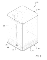
- FIG. 1 is an upper perspective view of the present invention.
- FIG. 2 is a lower perspective view of the present invention.
- FIG. 3 is a lower exploded perspective view of the present invention.
- FIG. 4 is a top view of the present invention.
- FIG. 5 is a bottom view of the present invention.
- FIG. 6 is a front view of the present invention.
- FIG. 7 is an exploded lower perspective view of the present invention with respect to a rectangular pedestal.
- FIG. 8 is an upper perspective view of the present invention attached to the upper end of the rectangular pedestal.
- FIG. 9 is a cross sectional view taken along line 9 - 9 of FIG. 8 .
- FIG. 10 is an exploded lower perspective view of the present invention with respect to a circular pedestal.
- FIG. 11 is an upper perspective view of the present invention attached to the upper end of the circular pedestal.
- FIG. 12 is a cross sectional view taken along line 12 - 12 of FIG. 11 .
- FIG. 13 is a magnified lower perspective view of the base illustrating the support members.
- FIGS. 1 through 13 illustrate an electrical enclosure 10 , which comprises housing having a base 30 and a cover 20 attached to the base 30 .
- the electrical enclosure 10 further comprises a mounting structure that allows for attachment of the base 30 to at least two different pedestals. While the present mounting structure illustrated shows attachment of the electrical enclosure 10 to two different types of pedestals (a rectangular pedestal 12 and a circular pedestal 14 ), additional different shapes and sizes of pedestals may be attached to the present invention. For example, two or more different circular pedestals 14 having different diameters could be attached to the electrical enclosure 10 .
- the mounting structure includes one or more support members that allow for attachment to a rectangular pedestal 12 or a circular pedestal 14 thereby allowing an installer to utilize their preferred pedestal type.
- the housing for the electrical enclosure 10 is comprised of a cover 20 , a base 30 and at least one mounting structure attached to the base 30 for mounting to different types of pedestals 12 , 14 .
- the housing is adapted to house and protect one or more electrical components within the electrical enclosure.
- the electrical enclosure 10 may be utilized to house and protect electrical devices such as control units, switches, gauges, alarms, sensors, displays and the like in various industries such as alarms for pump switches.
- the electrical enclosure 10 of the present invention is preferably designed to be positioned outside of a building structure where the electrical enclosure 10 is subject to the weather such as rain, snow, sun and wind. It is therefore important that the electrical enclosure 10 be mounted upon a pedestal 12 , 14 to keep the electronics inside the electrical enclosure 10 above the ground surface 11 .
- the cover 20 is preferably removably attached to the base 30 as illustrated in FIG. 3 of the drawings.
- the cover 20 may be permanently attached to the base 30 to form the housing of the electrical enclosure 10 defining an interior to house the one or more electrical components.
- the cover 20 may be comprised of various shapes and sizes, but it is preferable that the cover 20 have a lower opening 24 similar in shape and size to the base 30 to provide a snug and substantially sealed connection along the perimeter of the base 30 .
- the cover 20 may be transparent or semi-transparent to allow for viewing of the interior of the cover 20 (to also allow for visual alarms such as lights to be used to indicate an alarm situation such as high water within a sump pit).
- the cover 20 includes at least one first aperture 22 that receives a fastener 16 for securing the cover 20 to the base 30 . As illustrated in FIG. 3 , it is preferable to have at least two first apertures 22 on opposing sides of the cover 20 to secure both sides of the cover 20 to the base 30 .
- the first apertures 22 of the cover 20 are aligned with corresponding second apertures 36 within the outer wall 33 of the base 30 that allow the fasteners 16 to extend through the base 30 into the mounting structure and/or the upper portion of the pedestal 12 , 14 to secure the pedestal to the base 30 .
- the cover 20 further preferably includes one or more channels 26 that extend upwardly from the perimeter of the lower opening 24 of the cover 20 along an interior surface of the cover 20 to provide additional space for the head of a fastener 16 that extends through the second aperture 36 .
- the base 30 is adapted to be attached to an upper end of a pedestal 12 , 14 .
- the base 30 includes a support portion 31 that extends generally horizontally between an outer wall 33 that defines the perimeter of the base 30 .
- the support portion 31 is preferably planar and forms a floor for the electronic components housed in the electrical enclosure by the cover 20 .
- the support portion 31 further forms a ceiling for the recessed portion 38 that receives the pedestal 12 , 14 .
- the outer wall 33 extends downwardly from the support portion 31 of the base 30 to form a cavity 35 that receives the upper end of the pedestal 12 , 14 .
- the base 30 preferably has a rectangular shape, but it can be appreciated that various other shapes may be utilized for the base 30 that are capable of receiving different shaped pedestals 12 , 14 .
- the base 30 further includes an electronics support 32 that extends upwardly from the support portion 31 to support various electronic devices such as alarms (audible or visual), control units, switches and the like.
- the outer wall 33 further includes a flanged end 34 at the lower distal end of the outer wall 33 that the lower distal end of the cover 20 engages when positioned upon the base 30 .
- the base 30 includes at least one second aperture 36 within the outer wall 33 that receives a corresponding fastener 16 as illustrated in FIGS. 3 and 6 of the drawings. It is preferable to have a plurality of second apertures 36 within the outer wall 33 to receive a corresponding number of fasteners 16 thereby securing both the cover 20 and the base 30 to the pedestal 12 , 14 .
- One or more of the second apertures 36 includes a recessed portion 38 that receives the head of the fastener 16 thereby allowing the cover 20 to slide over the fastener 16 (in addition, the channel 26 within the cover 20 is preferably aligned with the same second aperture 36 to prevent engagement of the cover 20 with the head of the fastener 16 thereby allowing securing of the base 30 to the pedestal without having to attach the cover 20 ).
- the base 30 includes a mounting structure that is adapted to attach at least two different types of pedestals 12 , 14 .
- the pedestals 12 , 14 are typically constructed of plastic (e.g. polyvinyl chloride a.k.a. PVC) such as PVC pipes.
- the pedestals 12 , 14 are comprised of a structure and material that allows for the attachment of the base 30 thereto with conventional fasteners 16 (e.g. metal screws, bolts, threaded fasteners 16 ).
- Different types of pedestals includes pedestals having different cross sectional shapes (e.g. rectangular pedestal 12 as illustrated in FIG. 9 or a circular pedestal 14 as illustrated in FIG. 12 ).
- different types of pedestals includes pedestals having different sizes (e.g. different diameters, different widths).
- the mounting structure is adapted for attaching either a circular pedestal 14 or a rectangular pedestal 12 to the base 30 as illustrated in FIGS. 7 through 12 of the drawings.
- a single mounting structure may be utilized for attaching two or more types of pedestals, or a plurality of mounting structures may be utilized for attaching two or more types of pedestals.
- a first mounting structure and a second mounting structure could be attached to the base 30 , wherein the first mounting structure is adapted to attach a first type of pedestal to the base 30 and the second mounting structure is adapted to attach a second type of pedestal to the base 30 .
- the mounting structure is preferably comprised of at least one support member 40 a , 40 b , 40 c , 40 d having a first portion 42 having a curved surface 43 adapted to receive the circular pedestal 14 and a second portion 46 having a straight surface adapted to receive the rectangular pedestal 12 .
- the first portion 42 may extend to form a complete circle that receives the circular pedestal 14 .
- the first portion 42 preferably has an interior diameter approximately the same as the outer diameter of the circular pedestal 14 so that a curved surface 43 (interior) of the first portion 42 snugly receives the upper end of the circular pedestal 14 . It can be appreciated that the first portion 42 may also have an exterior diameter approximately the same as the interior diameter of the circular pedestal 14 so that the curved surface 43 (exterior) of the first portion 42 snugly fits within the upper opening of the circular pedestal 14 .
- FIGS. 5, 9 and 12 best illustrate where it is preferable to have four support members 40 a - b extending downwardly from the lower surface of the support portion 31 of the base 30 .
- Each of the support members is preferably comprised of a first portion 42 and a second portion 46 .
- the first portion 42 is preferably connected to the second portion 46 , however the second portion 46 may be separate from the first portion 42 .
- the first portion 42 has a curved surface 43 that faces inwardly that receives the outer surface of the circular pedestal 14 (or that faces outwardly when being positioned within the interior surface of the lumen of the circular pedestal 14 ).
- the second portion 46 preferably extends from the first portion 42 and has a straight surface that faces outwardly to fit within the interior surface of the upper end of the rectangular pedestal 12 .
- the interior surface of the outer wall 33 preferably is shaped and sized to receive the outer surface of the upper end of the rectangular pedestal 12 thereby retaining the upper end of the rectangular pedestal 12 between the second portion 46 and the outer wall 33 .
- the second portion 46 is preferably parallel with a portion of the outer wall 33 nearest to the second portion 46 as best illustrated in FIG. 5 of the drawings. The distance between the second portion 46 and the outer wall 33 is approximately the thickness of the wall of the rectangular pedestal 12 .
- One or more of the support members 40 a - b includes one or more securing apertures 48 that are preferably aligned with the second apertures 36 within the base 30 to receive a corresponding fastener 16 .
- the securing apertures 48 are further preferably positioned within the second portion 46 of the support members 40 a - b , however, it can be appreciated that the securing apertures 48 may extend through the first portion 42 .
- a brace portion 44 extends from the support portion 31 of the base 30 and is attached to the support members.
- the brace portion 44 for each of the support members 40 a - b preferably extends towards a respective adjacent interior corner of the outer wall 33 to avoid interfering with the insertion of the rectangular pedestal 12 as illustrated in FIG. 5 of the drawings.
- the install of the electrical enclosure 10 identifies the location of installation and the type of pedestal 12 , 14 they prefer to utilize.
- the installer attaches the selected pedestal to the ground surface 11 utilizing conventional attachment methods (e.g. burying the lower end within the ground surface 11 ).
- the installer then positions the base 30 upon the upper end of the pedestal 12 , 14 and then inserts one or more fasteners 16 through the outer wall 33 of the base 30 into the pedestal 12 , 14 .
- the user positions the cover 20 upon the base 30 and secures the cover 20 by inserting one or more fasteners 16 through the first apertures 22 within the cover 20 through the second apertures 36 and the through the pedestal 12 , 14 .
- the fasteners 16 may or may not extend through the support members 40 a - b .
- one or more openings may be created within the support portion 31 (either by the installer or by the manufacturer) to allow for wires to pass from electrical enclosure 10 downwardly through the support portion 31 for connection to sensors, switches and the like externally positioned of the electrical enclosure.
- FIGS. 7 through 9 illustrate attaching the base 30 to a rectangular pedestal 12 .
- the rectangular pedestal 12 fits between the second portions 46 of the support members 40 a - b and the fasteners 16 extend through the base 30 then through the rectangular pedestal 12 and then through the second portions 46 of the support members 40 a - b.
- FIGS. 10 through 12 illustrate attaching the base 30 to a circular pedestal 14 instead of a rectangular pedestal 12 .
- the circular pedestal 14 fits inside of the first portions 42 of the support members 40 a - b adjacent to the curved surface 43 (interior) of the first portions 42 .
- the fasteners 16 extend through the base 30 then through the circular pedestal 14 and then through the second portions 46 of the support members 40 a - b.
Landscapes
- Engineering & Computer Science (AREA)
- Microelectronics & Electronic Packaging (AREA)
- Power Engineering (AREA)
- Casings For Electric Apparatus (AREA)
Abstract
Description
Claims (19)
Priority Applications (1)
| Application Number | Priority Date | Filing Date | Title |
|---|---|---|---|
| US14/301,534 US9748744B2 (en) | 2014-06-11 | 2014-06-11 | Electrical enclosure with interchangeable pedestal mounting system |
Applications Claiming Priority (1)
| Application Number | Priority Date | Filing Date | Title |
|---|---|---|---|
| US14/301,534 US9748744B2 (en) | 2014-06-11 | 2014-06-11 | Electrical enclosure with interchangeable pedestal mounting system |
Publications (2)
| Publication Number | Publication Date |
|---|---|
| US20150364902A1 US20150364902A1 (en) | 2015-12-17 |
| US9748744B2 true US9748744B2 (en) | 2017-08-29 |
Family
ID=54836973
Family Applications (1)
| Application Number | Title | Priority Date | Filing Date |
|---|---|---|---|
| US14/301,534 Active US9748744B2 (en) | 2014-06-11 | 2014-06-11 | Electrical enclosure with interchangeable pedestal mounting system |
Country Status (1)
| Country | Link |
|---|---|
| US (1) | US9748744B2 (en) |
Families Citing this family (1)
| Publication number | Priority date | Publication date | Assignee | Title |
|---|---|---|---|---|
| USD1093136S1 (en) * | 2024-06-18 | 2025-09-16 | Christopher Corbett | Pedestal screw insert |
Citations (4)
| Publication number | Priority date | Publication date | Assignee | Title |
|---|---|---|---|---|
| US3696242A (en) * | 1971-06-15 | 1972-10-03 | Leon R Patry | Connector for a post-mounted lighting fixture |
| US4368842A (en) * | 1980-04-21 | 1983-01-18 | Delange Iii William | Mailbox protector |
| US5899420A (en) * | 1997-05-29 | 1999-05-04 | Gerardi; Karen L. | Mountable storage bin |
| US6116556A (en) * | 1999-02-05 | 2000-09-12 | C. E. W. Lighting, Inc. | Multi-mount for lighting and pole accessories |
-
2014
- 2014-06-11 US US14/301,534 patent/US9748744B2/en active Active
Patent Citations (4)
| Publication number | Priority date | Publication date | Assignee | Title |
|---|---|---|---|---|
| US3696242A (en) * | 1971-06-15 | 1972-10-03 | Leon R Patry | Connector for a post-mounted lighting fixture |
| US4368842A (en) * | 1980-04-21 | 1983-01-18 | Delange Iii William | Mailbox protector |
| US5899420A (en) * | 1997-05-29 | 1999-05-04 | Gerardi; Karen L. | Mountable storage bin |
| US6116556A (en) * | 1999-02-05 | 2000-09-12 | C. E. W. Lighting, Inc. | Multi-mount for lighting and pole accessories |
Non-Patent Citations (2)
| Title |
|---|
| "Observer 100" Series Pedestal Alarm, SPI Septic Products, Inc., 2 pages. |
| "PS Patrol™ system with 230V Pump & 120V Alarm Installation Instructions," SJE-Rhombus® Controls,4 pages. |
Also Published As
| Publication number | Publication date |
|---|---|
| US20150364902A1 (en) | 2015-12-17 |
Similar Documents
| Publication | Publication Date | Title |
|---|---|---|
| US10224594B2 (en) | Radio and power pole | |
| US9453517B1 (en) | Remote retainer bracket for hugger fan | |
| US20140062830A1 (en) | System and method for payload enclosure | |
| NO179428B (en) | Device for providing specific information, e.g. about emergency exits on ships, aircraft, in buildings or information on special land areas | |
| US7578255B2 (en) | Combination door knocker, peep hole, and decoration hanger | |
| US9748744B2 (en) | Electrical enclosure with interchangeable pedestal mounting system | |
| US20050167135A1 (en) | Electrical panel support stand | |
| US9445516B2 (en) | Weatherproof corner box | |
| EP3830362A1 (en) | Transferring appartus for pipeline and electricity wiring insertion into residential secured spaces | |
| US20150380913A1 (en) | Back box with mounting posts projecting from recessed portions in sidewalls | |
| US9920911B1 (en) | Exterior wall fixture | |
| CA2895732A1 (en) | Prefab lift station | |
| US9316018B2 (en) | Suspended dwelling | |
| JP6236675B2 (en) | Tubular member end fixing structure, mounting member, and tubular member end fixing method | |
| JP2009161969A (en) | Burglar intrusion prevention device | |
| JP6760853B2 (en) | Structure | |
| US5503359A (en) | Mounting box for ceiling fans | |
| EP3270222B1 (en) | Supporting pole for apparatuses | |
| JP5223479B2 (en) | Ventilation equipment | |
| JP6509679B2 (en) | Draw-through structure of wiring and piping material and penetration structure of wiring and piping material to the roof | |
| US20180198262A1 (en) | Multi-purpose decorative cover for electrical distribution systems | |
| US9360651B2 (en) | Covert rooftop vent enclosure and adjustable multi-tiered rack for electronic surveillance equipment | |
| US20120207587A1 (en) | Cooling system | |
| US12094308B2 (en) | Camera mounting arrangement | |
| RU203562U1 (en) | Universal junction box |
Legal Events
| Date | Code | Title | Description |
|---|---|---|---|
| AS | Assignment |
Owner name: S.J. ELECTRO SYSTEMS, INC., MINNESOTA Free format text: ASSIGNMENT OF ASSIGNORS INTEREST;ASSIGNOR:BERGUM, ALAN J.;REEL/FRAME:033075/0327 Effective date: 20140609 |
|
| STCF | Information on status: patent grant |
Free format text: PATENTED CASE |
|
| MAFP | Maintenance fee payment |
Free format text: PAYMENT OF MAINTENANCE FEE, 4TH YR, SMALL ENTITY (ORIGINAL EVENT CODE: M2551); ENTITY STATUS OF PATENT OWNER: SMALL ENTITY Year of fee payment: 4 |
|
| AS | Assignment |
Owner name: GOLUB CAPITAL LLC, NEW YORK Free format text: SECURITY INTEREST;ASSIGNORS:SJE-RHOMBUS PROPERTY, LLC;S.J. ELECTRO SYSTEMS, INC.;REEL/FRAME:056572/0185 Effective date: 20210617 Owner name: ALTER DOMUS (US) LLC, AS ADMINISTRATIVE AGENT, ILLINOIS Free format text: SECURITY INTEREST;ASSIGNORS:S.J. ELECTRO SYSTEMS, INC.;SJE-RHOMBUS PROPERTY, LLC;REEL/FRAME:056574/0223 Effective date: 20210617 |
|
| AS | Assignment |
Owner name: S.J. ELECTRO SYSTEMS, LLC, MINNESOTA Free format text: CHANGE OF NAME;ASSIGNOR:S.J. ELECTRO SYSTEMS, INC.;REEL/FRAME:058666/0823 Effective date: 20210618 |
|
| MAFP | Maintenance fee payment |
Free format text: PAYMENT OF MAINTENANCE FEE, 8TH YR, SMALL ENTITY (ORIGINAL EVENT CODE: M2552); ENTITY STATUS OF PATENT OWNER: SMALL ENTITY Year of fee payment: 8 |