US9746646B2 - Imaging lens assembly - Google Patents
Imaging lens assembly Download PDFInfo
- Publication number
- US9746646B2 US9746646B2 US15/225,262 US201615225262A US9746646B2 US 9746646 B2 US9746646 B2 US 9746646B2 US 201615225262 A US201615225262 A US 201615225262A US 9746646 B2 US9746646 B2 US 9746646B2
- Authority
- US
- United States
- Prior art keywords
- lens
- lens assembly
- imaging lens
- imaging
- refractive power
- Prior art date
- Legal status (The legal status is an assumption and is not a legal conclusion. Google has not performed a legal analysis and makes no representation as to the accuracy of the status listed.)
- Active
Links
Images


Classifications
-
- G—PHYSICS
- G02—OPTICS
- G02B—OPTICAL ELEMENTS, SYSTEMS OR APPARATUS
- G02B13/00—Optical objectives specially designed for the purposes specified below
- G02B13/001—Miniaturised objectives for electronic devices, e.g. portable telephones, webcams, PDAs, small digital cameras
- G02B13/0015—Miniaturised objectives for electronic devices, e.g. portable telephones, webcams, PDAs, small digital cameras characterised by the lens design
- G02B13/002—Miniaturised objectives for electronic devices, e.g. portable telephones, webcams, PDAs, small digital cameras characterised by the lens design having at least one aspherical surface
- G02B13/0045—Miniaturised objectives for electronic devices, e.g. portable telephones, webcams, PDAs, small digital cameras characterised by the lens design having at least one aspherical surface having five or more lenses
-
- G—PHYSICS
- G02—OPTICS
- G02B—OPTICAL ELEMENTS, SYSTEMS OR APPARATUS
- G02B9/00—Optical objectives characterised both by the number of the components and their arrangements according to their sign, i.e. + or -
- G02B9/62—Optical objectives characterised both by the number of the components and their arrangements according to their sign, i.e. + or - having six components only
Definitions
- the present disclosure relates to optical technologies, and more particular, to an imaging lens assembly applicable to a digital camera of a mobile phone or a WEB camera, which uses CCD imaging components or CMOS imaging components with high resolution.
- CCD imaging components and CMOS imaging components are used widely in camera device, to meet the requirements of miniaturization and good performance of the imaging components, a wide-angle lens assembly with good optical characteristic, thin profile, and high luminous flux (namely, F number) is needed.
- Japanese patent No. 5651881 discloses an imaging lens assembly including six lenses. However, a proportion of a total track length (TTL) and an image height (IH) of the imaging lens assembly is greater than 1.46; this is, TTL/IH ⁇ 1.46. Accordingly, the imaging lens assembly is too thick to meet the miniaturization requirement.
- TTL total track length
- IH image height
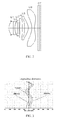
- FIG. 1 is a schematic view of an imaging lens assembly according to an embodiment of the present disclosure, with parameter symbols labeled thereon;
- FIG. 2 schematically illustrates an imaging lens assembly according to the first exemplified embodiment
- FIG. 3 schematically illustrates the longitudinal aberration of the imaging lens assembly of FIG. 2 ;
- FIG. 4 schematically illustrates the lateral color of the imaging lens assembly of FIG. 2 ;
- FIG. 5 schematically illustrates the field curvature and distortion of the imaging lens assembly of FIG. 2 ;
- FIG. 6 schematically illustrates an imaging lens assembly according to the second exemplified embodiment
- FIG. 7 schematically illustrates the longitudinal aberration of the imaging lens assembly of FIG. 6 ;
- FIG. 8 schematically illustrates the Lateral color of the imaging lens assembly of FIG. 6 ;
- FIG. 9 schematically illustrates the field curvature and distortion of the imaging lens assembly of FIG. 6 .
- the imaging lens assembly LA includes a lens set with six lenses, that is, a first lens L1, a second lens L2, a third lens L3, a fourth lens L4, a fifth lens L5 and a sixth lens L6, which are arranged in that order from the object side to the image plane.
- a glass filter GF is arranged between the sixth lens L6 and the image plane.
- the glass filter GF may be a cover glass or an IR filter. Alternatively, the glass filter GF may be arranged in other location or even removed from the imaging lens assembly LA.
- the first lens L1 has a positive refractive power
- the second lens L2 has a negative refractive power
- the third lens L3 also has a negative refractive power
- the fourth lens L4 may have a positive or negative refractive power
- the fifth lens L5 has a positive refractive power
- the sixth lens L6 has a negative refractive power.
- the six lenses L1 to L6 may be designed to have aspheric surfaces, so as to compensate aberration in the imaging lens assembly LA.
- the imaging lens assembly LA satisfies the following conditions (1) to (4): 0.60 ⁇ f 1/ f ⁇ 0.80 (1) ⁇ 2.00 ⁇ ( R 1+ R 2)/( R 1 ⁇ R 2) ⁇ 1.10 (2) 1.15 ⁇ ( R 3+ R 4)/( R 3 ⁇ R 4) ⁇ 1.40 (3) ⁇ 7.50 ⁇ ( R 5+ R 6)/( R 5 ⁇ R 6) ⁇ 3.00 (4)
- f is the focal length of the imaging lens assembly LA
- f1 is the focal length of the first lens L1;
- R1 is the curvature radius of the object side of the first lens L1;
- R2 is the curvature radius of the image side of the first lens L1;
- R3 is the curvature radius of the object side of the second lens L2;
- R4 is the curvature radius of the image side of the second lens L2;
- R5 is the curvature radius of the object side of the third lens L3.
- R6 is the curvature radius of the image side of the third lens L3.
- the condition (1) defines the positive refractive power of the first lens L1. If the value excesses the minimum limit, it is better for the miniaturization of the imaging lens assembly LA; however, the positive refractive power of the first lens L1 is too strong to compensate aberration. In contrast, if the value excesses the maximum limit, the positive refractive power of the first lens L1 is too weak, and is adverse to the miniaturization of the imaging lens assembly LA.
- the proportion value f1/f in condition (1) is preferred to be set in the value range as defined in the following condition (1-A): 0.66 ⁇ f 1/ f ⁇ 0.80 (1-A)
- condition (2) defines the shape of the first lens L1. If the proportion value (R1+R2)/(R1 ⁇ R2) is beyond the value range defined by condition (2), it is difficult to compensate high order aberration such as the spherical aberration when the imaging lens assembly LA has a less thickness and a wider view angle with an F number (Fno) less than 2.2.
- the proportion value (R1+R2)/(R1 ⁇ R2) in condition (2) is preferred to be set in the value range as defined in the following condition (2-A): ⁇ 1.80 ⁇ ( R 1+ R 2)/( R 1 ⁇ R 2) ⁇ 1.10 (2-A)
- condition (3) defines the shape of the second lens L2. If the proportion value (R3+R4)/(R3 ⁇ R4) is beyond the value range defined by condition (3), it is difficult to compensate the on-axis chromatic aberration when the imaging lens assembly LA has a less thickness and a wider view angle with an F number (Fno) less than 2.2.
- the proportion value (R3+R4)/(R3 ⁇ R4) in condition (3) is preferred to be set in the value range as defined in the following condition (3-A): 1.17 ⁇ ( R 3+ R 4)/( R 3 ⁇ R 4) ⁇ 1.38 (3-A)
- the condition (4) defines the shape of the third lens L3. If the proportion value (R5+R6)/(R5 ⁇ R6) is beyond the value range defined by condition (4), it is difficult to compensate the Lateral Color when the imaging lens assembly LA has a less thickness and a wider view angle with an F number (Fno) less than 2.2.
- the proportion value (R5+R6)/(R5 ⁇ R6) in condition (4) is preferred to be set in the value range as defined in the following condition (4-A): ⁇ 6.50 ⁇ ( R 5+ R 6)/( R 5 ⁇ R 6) ⁇ 3.50 (4-A)
- the second lens L2 may have a negative refractive power, which satisfies the following condition (5): ⁇ 2.00 ⁇ f 2/ f ⁇ 1.00 (5)
- f is the focal length of the imaging lens assembly
- f2 is the focal length of the second lens L2.
- condition (5) defines the negative refractive power of the second lens L2. If the proportion value f2/f is beyond the value range defined by condition (5), it is difficult to compensate the on-axis chromatic aberration when the imaging lens assembly LA has a less thickness and a wider view angle with an F number (Fno) less than 2.2.
- the imaging lens assembly LA is possible to have good optical characteristic as well as an ultra-thin profile, and moreover, the imaging lens assembly LA may also satisfy the following parameter requirements: TTL/IH ⁇ 1.35, view angle 2 ⁇ 76°, and Fno ⁇ 2.2.
- parameters of the imaging lens assembly LA are defined as follows, in which the unit of each of distance, radius, and central thickness is millimeter (mm):
- Fno F-number; 2 ⁇ : full view angle;
- R the curvature radius of an optical surface, and may also be the central curvature radius of the lens
- R1 the curvature radius of the object side of the first lens L1;
- R2 the curvature radius of the image side of the first lens L1;
- R3 the curvature radius of the object side of the second lens L2;
- R4 the curvature radius of the image side of the second lens L2;
- R5 the curvature radius of the object side of the third lens L3;
- R6 the curvature radius of the image side of the third lens L3;
- R7 the curvature radius of the object side of the fourth lens L4;
- R8 the curvature radius of the image side of the fourth lens L4;
- R9 the curvature radius of the object side of the fifth lens L5;
- R10 the curvature radius of the image side of the fifth lens L5;
- R11 the curvature radius of the object side of the sixth lens L6;
- R12 the curvature radius of the image side of the sixth lens L6;
- R13 the curvature radius of the object side of the glass filter GF
- R14 the curvature radius of the image side of the glass filter GF
- d an axial thickness of the lens or an axial distance between lenses
- d0 the axial distance between the aperture stop and the object side of the first lens L1;
- d2 the axial distance between the image side of the first lens L1 and the object side of the second lens L2;
- d4 the axial distance between the image side of the second lens L2 and the object side of the third lens L3;
- d6 the axial distance between the image side of the third lens L3 and the object side of the fourth lens L4;
- d10 the axial distance between the image side of the fifth lens L5 and the object side of the sixth lens L6;
- d11 the central thickness of the sixth lens L6;
- d12 the axial distance between the image side of the sixth lens L6 and the object side of the glass filter GF;
- nd1 d line refraction index of the first lens L1;
- nd2 d line refraction index of the second lens L2;
- nd3 d line refraction index of the third lens L3;
- nd4 d line refraction index of the fourth lens L4;
- nd5 d line refraction index of the fifth lens L5;
- nd6 d line refraction index of the sixth lens L6;
- nd7 d line refraction index of the glass filter GF
- ⁇ d abbe number (i.e., dispersion coefficient)
- ⁇ 2 abbe number of the second lens L2
- ⁇ 4 abbe number of the fourth lens L4
- ⁇ 6 abbe number of the sixth lens L6
- TTL the total track length (i.e., an axial distance between the object side of the first lens L1 and the image plane);
- LB the axial distance between the image side of the second lens L6 and the image plane (including a thickness of the glass plate GF);
- IH the image height.
- y ( x 2 /R )/[1+ ⁇ 1 ⁇ ( k+ 1)( x 2 /R 2 ) ⁇ 1/2 ]+A 4 x 4 +A 6 x 6 +A 8 x 8 +A 10 x 10 +A 12 x 12 +A 14 x 14 +A 16 x 16 (6)
- R refers to an axial curvature radius
- k refers to a conic coefficient
- A4, A6, A8, A10, A12, A14 and A16 are aspherical coefficients.
- aspherical surfaces of the lenses L1-L6 may be obtained according to condition (6); alternatively, the aspherical surfaces may also be obtained according to other conditions.
- FIG. 2 illustrated an imaging lens assembly LA in accordance with the first exemplified embodiment of the present disclosure.
- TABLE 1 and TABLE 2 show the detailed optical data of the imaging lens assembly LA.
- the optical data in TABLE 1 includes the curvature radius R, the axial thickness d, the axial distance between lenses d, refraction index nd and abbe number ⁇ d of the lenses L1 to L6 in the imaging lens assembly LA.
- the optical data in TABLE 2 includes conic coefficient (C-coefficient) k and aspherical coefficient of the lenses L1 to L6 in the imaging lens assembly LA.
- the imaging lens assembly LA in the first embodiment satisfies the aforesaid conditions (1) to (5).
- FIGS. 3-5 schematically illustrate the longitudinal aberration, the lateral color, the field curvature and distortion of the imaging lens assembly LA as provided in the first embodiment respectively.
- curve S represents the field curvature related to the sagittal plane
- curve T represents the field curvature related to the tangential plane.
- the view angle 2 ⁇ of the imaging lens assembly LA is 82.8°
- the proportion value TTL/IH of the imaging lens assembly LA is 1.346
- the F number is 2.05.
- the imaging lens assembly LA as provided in the first embodiment has an ultra-thin profile and a wide-angle with high luminous flux, and accordingly has good optical characteristics.
- FIG. 6 illustrated an imaging lens assembly LA in accordance with the second embodiment of the present disclosure.
- TABLE 3 and TABLE 4 show the detailed optical data of the imaging lens assembly LA.
- the optical data in TABLE 3 includes the curvature radius R, the axial thickness d, the axial distance between lenses d, refraction index nd and abbe number ⁇ d of the lenses L1 to L6 in the imaging lens assembly LA.
- the optical data in TABLE 4 includes conic coefficient (C-coefficient) k and aspherical coefficient of the lenses L1 to L6 in the imaging lens assembly LA.
- the relevant optical data of the imaging lens assembly LA in the second embodiment and the values defined in the aforesaid conditions (1) to (5) are shown in TABLE 5 as provided in the subsequent paragraphs. As can be seen in TABLE 5, the imaging lens assembly LA in the second embodiment satisfies the aforesaid conditions (1) to (5).
- FIGS. 7-9 schematically illustrate the longitudinal aberration, the lateral color, the field curvature and distortion of the imaging lens assembly LA as provided in the second exemplified embodiment respectively.
- curve S represents the field curvature related to the sagittal plane
- curve T represents the field curvature related to the tangential plane.
- the view angle 2 ⁇ of the imaging lens assembly LA is 82.6°
- the proportion value TTL/IH of the imaging lens assembly LA is 1.347
- the F number is 2.05.
- the imaging lens assembly LA as provided in the second embodiment has an ultra-thin profile and a wide-angle with high luminous flux, and accordingly has good optical characteristics.
- TABLE 5 shows the values of the imaging lens assembly LA in relevant to the conditions (1) to (5) according to both the first embodiment and the second embodiment. Moreover, in TABLE 5, the unit of the value 2 ⁇ is degree (°), and the units of the values f, f1, f2, f3, f4, f5, f6, TTL, LB and IH are millimeter (mm).
- Embodiment 1 Embodiment 2 Formulae f1/f 0.78 0.79 Formula (1) (R1 + R2)/(R1 ⁇ R2) ⁇ 1.15 ⁇ 1.24 Formula (2) (R3 + R4)/(R3 ⁇ R4) 1.20 1.23 Formula (3) (R5 + R6)/(R5 ⁇ R6) ⁇ 4.39 ⁇ 4.49 Formula (4) f2/f ⁇ 1.49 ⁇ 1.54 Formula (5) Fno 2.05 2.05 2 ⁇ 82.8 82.6 TTL/IH 1.346 1.347 f 3.874 3.906 f1 3.012 3.072 f2 ⁇ 5.791 ⁇ 6.025 f3 ⁇ 245.459 ⁇ 264.018 f4 109.613 120.227 f5 2.891 2.897 f6 ⁇ 2.392 ⁇ 2.390 TTL 4.676 4.682 LB 0.919 0.909 IH 3.475 3.475
- the imaging lens assembly LA as provided in the present disclosure has good optical characteristic, high luminous flux as well as an ultra-thin profile, and moreover, the imaging lens assembly LA satisfies the following parameter requirements: TTL/IH ⁇ 1.35, view angle 2 ⁇ 76°, and Fno ⁇ 2.2. Therefore, the imaging lens assembly LA is applicable to a digital camera of a mobile phone or a WEB camera, which uses CCD imaging components or CMOS imaging components with high resolution.
Landscapes
- Physics & Mathematics (AREA)
- General Physics & Mathematics (AREA)
- Optics & Photonics (AREA)
- Lenses (AREA)
Abstract
Description
0.60≦f1/f≦0.80 (1)
−2.00≦(R1+R2)/(R1−R2)≦−1.10 (2)
1.15≦(R3+R4)/(R3−R4)≦1.40 (3)
−7.50≦(R5+R6)/(R5−R6)≦−3.00 (4)
0.66≦f1/f≦0.80 (1-A)
−1.80≦(R1+R2)/(R1−R2)≦−1.10 (2-A)
1.17≦(R3+R4)/(R3−R4)≦1.38 (3-A)
−6.50≦(R5+R6)/(R5−R6)≦−3.50 (4-A)
−2.00≦f2/f≦−1.00 (5)
y=(x 2 /R)/[1+{1−(k+1)(x 2 /R 2)}1/2 ]+A4x 4 +A6x 6 +A8x 8 +A10x 10 +A12x 12 +A14x 14 +A16x 16 (6)
| TABLE 1 | ||||
| R | d | nd | νd | |
| S1 | ∞ | d0 = | −0.310 | ||||
| R1 | 1.53995 | d1 = | 0.586 | nd1 | 1.5441 | ν1 | 56.12 |
| R2 | 22.07678 | d2 = | 0.058 | ||||
| R3 | 37.19457 | d3 = | 0.243 | nd2 | 1.6448 | ν2 | 22.44 |
| R4 | 3.38460 | d4 = | 0.373 | ||||
| R5 | −58.09431 | d5 = | 0.238 | nd3 | 1.6397 | ν3 | 23.53 |
| R6 | −92.35499 | d6 = | 0.080 | ||||
| R7 | 4.91476 | d7 = | 0.366 | nd4 | 1.5441 | ν4 | 56.12 |
| R8 | 5.21559 | d8 = | 0.366 | ||||
| R9 | −7.46637 | d9 = | 0.519 | nd5 | 1.5352 | ν5 | 56.12 |
| R10 | −1.31277 | d10 = | 0.510 | ||||
| R11 | −2.88094 | d11 = | 0.418 | nd6 | 1.5352 | ν6 | 56.12 |
| R12 | 2.42017 | d12 = | 0.520 | ||||
| R13 | ∞ | d13 = | 0.210 | nd7 | 1.5168 | ν6 | 64.17 |
| R14 | ∞ | d14 = | 0.189 | ||||
| TABLE 2 | ||
| C-coefficient | aspherical coefficient | |
| k | A4 | A6 | A8 | A10 | A12 | A14 | A16 | |
| R1 | −3.3341E−01 | 1.3666E−03 | 2.9702E−02 | −2.1774E−02 | −9.3438E−03 | 1.5200E−02 | 1.3663E−02 | −2.5549E−02 |
| R2 | 0.0000E+00 | −2.5760E−02 | 1.4567E−02 | 3.6346E−02 | −3.8835E−02 | −5.7498E−02 | 2.4410E−03 | 3.5800E−02 |
| R3 | −1.3537E+03 | −9.8237E−03 | 3.2261E−02 | 2.2134E−02 | 6.4311E−04 | −4.2221E−02 | −7.0047E−02 | 9.4446E−02 |
| R4 | −2.9129E+00 | 2.4410E−02 | 8.8216E−03 | 9.4199E−02 | 3.1828E−02 | −1.0801E−01 | −1.3076E−01 | 1.9366E−01 |
| R5 | −4.4128E+02 | −2.3399E−02 | −6.2691E−02 | −2.9843E−02 | 3.2513E−02 | 4.9103E−02 | 2.2515E−02 | −5.1583E−02 |
| R6 | 4.8417E+03 | −2.6769E−02 | −7.1330E−02 | 5.2181E−03 | 3.6132E−02 | 2.1292E−02 | −2.2877E−04 | −1.1071E−02 |
| R7 | 0.0000E+00 | −1.3306E−01 | 1.0505E−02 | 1.0562E−02 | 5.7542E−03 | 2.2628E−03 | −4.7011E−04 | −1.2293E−03 |
| R8 | 0.0000E+00 | −1.0952E−01 | 1.2147E−02 | 4.9050E−03 | −1.6616E−03 | −8.6107E−04 | 7.5762E−05 | 1.4271E−04 |
| R9 | 7.3469E+00 | −1.8669E−02 | −1.2579E−02 | 2.0484E−03 | −1.7373E−03 | 9.7874E−05 | 1.9435E−04 | 1.2021E−05 |
| R10 | −3.7865E+00 | −3.5819E−02 | 1.7662E−02 | −1.1281E−03 | −6.2566E−05 | −7.5645E−05 | −4.2074E−06 | 2.8034E−06 |
| R11 | 0.0000E+00 | −2.2345E−05 | 4.0238E−03 | 5.8035E−05 | −2.8897E−05 | −2.0160E−06 | 5.9500E−08 | 4.9453E−08 |
| R12 | −1.9599E+01 | −2.7118E−02 | 4.0662E−03 | −7.5953E−04 | 3.2209E−05 | 1.5758E−06 | 6.4623E−08 | 2.7787E−09 |
| TABLE 3 | ||||
| R | d | nd | νd | |
| S1 | ∞ | d0 = | −0.310 | ||||
| R1 | 1.51908 | d1 = | 0.600 | nd1 | 1.5441 | ν1 | 56.12 |
| R2 | 14.33117 | d2 = | 0.059 | ||||
| R3 | 34.18880 | d3 = | 0.240 | nd2 | 1.6448 | ν2 | 22.44 |
| R4 | 3.47890 | d4 = | 0.377 | ||||
| R5 | −61.38130 | d5 = | 0.242 | nd3 | 1.6397 | ν3 | 23.53 |
| R6 | −96.57146 | d6 = | 0.078 | ||||
| R7 | 4.91934 | d7 = | 0.372 | nd4 | 1.5441 | ν4 | 56.12 |
| R8 | 5.17762 | d8 = | 0.373 | ||||
| R9 | −7.49478 | d9 = | 0.512 | nd5 | 1.5352 | ν5 | 56.12 |
| R10 | −1.31517 | d10 = | 0.506 | ||||
| R11 | −2.87700 | d11 = | 0.414 | nd6 | 1.5352 | ν6 | 56.12 |
| R12 | 2.41807 | d12 = | 0.520 | ||||
| R13 | ∞ | d13 = | 0.210 | nd7 | 1.5168 | ν6 | 64.17 |
| R14 | ∞ | d14 = | 0.179 | ||||
| TABLE 4 | ||
| C-coefficient | aspherical coefficient | |
| k | A4 | A6 | A8 | A10 | A12 | A14 | A16 | |
| R1 | −4.0088E−01 | −3.6777E−03 | 2.8909E−02 | −2.1526E−02 | −9.0835E−03 | 1.5311E−02 | 1.3637E−02 | −2.5670E−02 |
| R2 | 0.0000E+00 | −3.7770E−02 | 1.0818E−02 | 3.5228E−02 | −3.8826E−02 | −5.6957E−02 | 3.2369E−03 | 3.6712E−02 |
| R3 | 1.6578E+01 | −8.8559E−03 | 3.1152E−02 | 2.1504E−02 | 1.9774E−04 | −4.2649E−02 | −7.0497E−02 | 9.3977E−02 |
| R4 | −2.4633E+00 | 2.7059E−02 | 2.1201E−02 | 9.8279E−02 | 3.1597E−02 | −1.0982E−01 | −1.3285E−01 | 1.9187E−01 |
| R5 | −7.6696E+03 | −2.0749E−02 | −6.0434E−02 | −2.9271E−02 | 3.2567E−02 | 4.9881E−02 | 2.4601E−02 | −4.7741E−02 |
| R6 | 5.0291E+03 | −2.6963E−02 | −7.2019E−02 | 4.9280E−03 | 3.6069E−02 | 2.1300E−02 | −1.8706E−04 | −1.1035E−02 |
| R7 | 0.0000E+00 | −1.3337E−01 | 1.0544E−02 | 1.0671E−02 | 5.8292E−03 | 2.3010E−03 | −4.5915E−04 | −1.2376E−03 |
| R8 | 0.0000E+00 | −1.0851E−01 | 1.2129E−02 | 4.7722E−03 | −1.7231E−03 | −8.8050E−04 | 7.1875E−05 | 1.4344E−04 |
| R9 | 7.7607E+00 | −1.8893E−02 | −1.2732E−02 | 1.9952E−03 | −1.7485E−03 | 9.3804E−05 | 1.9170E−04 | 1.0511E−05 |
| R10 | −3.7863E+00 | −3.5794E−02 | 1.7648E−02 | −1.1418E−03 | −6.7872E−05 | −7.6966E−05 | −4.3165E−06 | 2.9216E−06 |
| R11 | 0.0000E+00 | −9.3462E−05 | 4.0190E−03 | 5.7923E−05 | −2.8853E−05 | −2.0041E−06 | 6.2658E−08 | 5.0407E−08 |
| R12 | −2.0452E+01 | −2.7121E−02 | 4.0868E−03 | −7.5667E−04 | 3.2432E−05 | 1.5889E−06 | 6.4978E−08 | 2.6980E−09 |
| TABLE 5 | ||||
| |
Embodiment 2 | Formulae | ||
| f1/f | 0.78 | 0.79 | Formula (1) |
| (R1 + R2)/(R1 − R2) | −1.15 | −1.24 | Formula (2) |
| (R3 + R4)/(R3 − R4) | 1.20 | 1.23 | Formula (3) |
| (R5 + R6)/(R5 − R6) | −4.39 | −4.49 | Formula (4) |
| f2/f | −1.49 | −1.54 | Formula (5) |
| Fno | 2.05 | 2.05 | |
| 2ω | 82.8 | 82.6 | |
| TTL/IH | 1.346 | 1.347 | |
| f | 3.874 | 3.906 | |
| f1 | 3.012 | 3.072 | |
| f2 | −5.791 | −6.025 | |
| f3 | −245.459 | −264.018 | |
| f4 | 109.613 | 120.227 | |
| f5 | 2.891 | 2.897 | |
| f6 | −2.392 | −2.390 | |
| TTL | 4.676 | 4.682 | |
| LB | 0.919 | 0.909 | |
| IH | 3.475 | 3.475 | |
Claims (2)
0.60≦f1/f≦0.80 (1)
−2.00≦(R1+R2)/(R1−R2)≦−1.10 (2)
1.15≦(R3+R4)/(R3−R4)≦1.40 (3)
−7.50≦(R5+R6)/(R5−R6)≦−3.00 (4)
−2.00≦f2/f≦−1.00 (5)
Applications Claiming Priority (5)
| Application Number | Priority Date | Filing Date | Title |
|---|---|---|---|
| JP2015182246A JP5841290B1 (en) | 2015-09-15 | 2015-09-15 | Imaging lens |
| JP2015-182246 | 2015-09-15 | ||
| CN201610280582.2A CN105911674B (en) | 2015-09-15 | 2016-04-30 | Pick-up lens |
| CN201610280582.2 | 2016-04-30 | ||
| CN201610280582 | 2016-04-30 |
Publications (2)
| Publication Number | Publication Date |
|---|---|
| US20170075090A1 US20170075090A1 (en) | 2017-03-16 |
| US9746646B2 true US9746646B2 (en) | 2017-08-29 |
Family
ID=55073258
Family Applications (1)
| Application Number | Title | Priority Date | Filing Date |
|---|---|---|---|
| US15/225,262 Active US9746646B2 (en) | 2015-09-15 | 2016-08-01 | Imaging lens assembly |
Country Status (3)
| Country | Link |
|---|---|
| US (1) | US9746646B2 (en) |
| JP (1) | JP5841290B1 (en) |
| CN (1) | CN105911674B (en) |
Families Citing this family (11)
| Publication number | Priority date | Publication date | Assignee | Title |
|---|---|---|---|---|
| JP6403711B2 (en) * | 2016-04-04 | 2018-10-10 | カンタツ株式会社 | Imaging lens |
| CN107966785B (en) * | 2016-10-19 | 2021-09-03 | 东京晨美光学电子株式会社 | camera lens |
| CN106814441B (en) * | 2016-12-14 | 2019-05-31 | 瑞声科技(新加坡)有限公司 | Camera optics |
| US10613293B2 (en) * | 2018-02-11 | 2020-04-07 | AAC Technologies Pte. Ltd. | Camera optical lens |
| US10712534B2 (en) * | 2018-02-11 | 2020-07-14 | Aac Optics Solutions Pte. Ltd. | Camera optical lens |
| JP6518364B1 (en) * | 2018-04-26 | 2019-05-22 | エーエーシー テクノロジーズ ピーティーイー リミテッド | Imaging optical lens |
| JP6526296B1 (en) * | 2018-04-26 | 2019-06-05 | エーエーシー テクノロジーズ ピーティーイー リミテッド | Imaging optical lens |
| JP6556927B1 (en) * | 2018-08-14 | 2019-08-07 | エーエーシー テクノロジーズ ピーティーイー リミテッド | Imaging optical lens |
| CN109239890B (en) | 2018-09-29 | 2019-11-05 | 江西联益光学有限公司 | Micro pick-up lens |
| CN113514935B (en) | 2021-04-25 | 2023-04-07 | 浙江舜宇光学有限公司 | Optical imaging lens |
| CN116594154B (en) * | 2023-07-13 | 2023-10-27 | 江西联益光学有限公司 | Optical lens |
Citations (2)
| Publication number | Priority date | Publication date | Assignee | Title |
|---|---|---|---|---|
| US8885268B2 (en) * | 2013-01-04 | 2014-11-11 | Largan Precision Co., Ltd. | Optical image collecting system |
| US9618725B2 (en) * | 2014-08-13 | 2017-04-11 | AAC Technologies Pte. Ltd. | Imaging lens assembly |
Family Cites Families (7)
| Publication number | Priority date | Publication date | Assignee | Title |
|---|---|---|---|---|
| TWI432772B (en) * | 2011-06-10 | 2014-04-01 | Largan Precision Co Ltd | Optical image capturing lens assembly |
| TWI435138B (en) * | 2011-06-20 | 2014-04-21 | Largan Precision Co | Optical imaging system for pickup |
| TWI437258B (en) * | 2011-08-05 | 2014-05-11 | Largan Precision Co Ltd | Optical lens assembly for image taking |
| JP5924121B2 (en) * | 2012-05-22 | 2016-05-25 | 株式会社オプトロジック | Imaging lens |
| CN205281004U (en) * | 2013-03-25 | 2016-06-01 | 富士胶片株式会社 | Pick -up lens and image pick -up device equipped with same |
| KR102063899B1 (en) * | 2013-07-10 | 2020-01-08 | 삼성전자주식회사 | Photographing lens and photographing apparatus |
| JP2015194528A (en) * | 2014-03-31 | 2015-11-05 | 富士フイルム株式会社 | Image capturing lens and image capturing device having the same |
-
2015
- 2015-09-15 JP JP2015182246A patent/JP5841290B1/en active Active
-
2016
- 2016-04-30 CN CN201610280582.2A patent/CN105911674B/en active Active
- 2016-08-01 US US15/225,262 patent/US9746646B2/en active Active
Patent Citations (2)
| Publication number | Priority date | Publication date | Assignee | Title |
|---|---|---|---|---|
| US8885268B2 (en) * | 2013-01-04 | 2014-11-11 | Largan Precision Co., Ltd. | Optical image collecting system |
| US9618725B2 (en) * | 2014-08-13 | 2017-04-11 | AAC Technologies Pte. Ltd. | Imaging lens assembly |
Also Published As
| Publication number | Publication date |
|---|---|
| CN105911674A (en) | 2016-08-31 |
| JP2017058477A (en) | 2017-03-23 |
| US20170075090A1 (en) | 2017-03-16 |
| JP5841290B1 (en) | 2016-01-13 |
| CN105911674B (en) | 2018-08-14 |
Similar Documents
| Publication | Publication Date | Title |
|---|---|---|
| US10989902B2 (en) | Camera lens | |
| US9671593B2 (en) | Imaging lens assembly | |
| US9746646B2 (en) | Imaging lens assembly | |
| US10816772B2 (en) | Camera lens | |
| US9759894B2 (en) | Camera lens | |
| US10775594B2 (en) | Camera lens | |
| US9703078B1 (en) | Camera lens | |
| US9835832B2 (en) | Camera lens | |
| US10168509B2 (en) | Camera lens | |
| US9618725B2 (en) | Imaging lens assembly | |
| US9678314B2 (en) | Imaging lens assembly | |
| US9104013B2 (en) | Imaging lens | |
| US20200026041A1 (en) | Camera Lens | |
| US9772473B2 (en) | Imaging lens assembly | |
| CN105911675B (en) | Pick-up lens | |
| US11333850B2 (en) | Camera lens | |
| US20170315335A1 (en) | Camera Lens | |
| CN106842501B (en) | Pick-up lens | |
| US9759895B1 (en) | Camera lens | |
| US10641996B2 (en) | Camera optical lens | |
| US20190227283A1 (en) | Camera Lens | |
| US9772474B2 (en) | Imaging lens assembly | |
| US10598899B2 (en) | Camera lens | |
| US10641998B2 (en) | Camera lens | |
| US10641999B2 (en) | Camera lens |
Legal Events
| Date | Code | Title | Description |
|---|---|---|---|
| AS | Assignment |
Owner name: AAC TECHNOLOGIES PTE. LTD., SINGAPORE Free format text: ASSIGNMENT OF ASSIGNORS INTEREST;ASSIGNOR:TERAOKA, HIROYUKI;REEL/FRAME:042271/0501 Effective date: 20160608 |
|
| FEPP | Fee payment procedure |
Free format text: PAYOR NUMBER ASSIGNED (ORIGINAL EVENT CODE: ASPN) |
|
| STCF | Information on status: patent grant |
Free format text: PATENTED CASE |
|
| AS | Assignment |
Owner name: AAC OPTICS SOLUTIONS PTE. LTD., SINGAPORE Free format text: ASSIGNMENT OF ASSIGNORS INTEREST;ASSIGNOR:AAC TECHNOLOGIES PTE. LTD.;REEL/FRAME:052411/0250 Effective date: 20200311 |
|
| MAFP | Maintenance fee payment |
Free format text: PAYMENT OF MAINTENANCE FEE, 4TH YEAR, LARGE ENTITY (ORIGINAL EVENT CODE: M1551); ENTITY STATUS OF PATENT OWNER: LARGE ENTITY Year of fee payment: 4 |
|
| MAFP | Maintenance fee payment |
Free format text: PAYMENT OF MAINTENANCE FEE, 8TH YEAR, LARGE ENTITY (ORIGINAL EVENT CODE: M1552); ENTITY STATUS OF PATENT OWNER: LARGE ENTITY Year of fee payment: 8 |