US974486A - Locomotive. - Google Patents
Locomotive. Download PDFInfo
- Publication number
- US974486A US974486A US55609710A US1910556097A US974486A US 974486 A US974486 A US 974486A US 55609710 A US55609710 A US 55609710A US 1910556097 A US1910556097 A US 1910556097A US 974486 A US974486 A US 974486A
- Authority
- US
- United States
- Prior art keywords
- drum
- smoke
- open
- smoke box
- drums
- Prior art date
- Legal status (The legal status is an assumption and is not a legal conclusion. Google has not performed a legal analysis and makes no representation as to the accuracy of the status listed.)
- Expired - Lifetime
Links
- 230000003137 locomotive effect Effects 0.000 title description 11
- 239000000779 smoke Substances 0.000 description 32
- 239000000463 material Substances 0.000 description 12
- 239000007789 gas Substances 0.000 description 7
- 239000003818 cinder Substances 0.000 description 6
- 238000010276 construction Methods 0.000 description 4
- 238000002485 combustion reaction Methods 0.000 description 3
- 239000002184 metal Substances 0.000 description 3
- 229910052751 metal Inorganic materials 0.000 description 3
- 230000000694 effects Effects 0.000 description 2
- 238000004140 cleaning Methods 0.000 description 1
- 230000001771 impaired effect Effects 0.000 description 1
- XEEYBQQBJWHFJM-UHFFFAOYSA-N iron Substances [Fe] XEEYBQQBJWHFJM-UHFFFAOYSA-N 0.000 description 1
- 229910052742 iron Inorganic materials 0.000 description 1
- 210000003141 lower extremity Anatomy 0.000 description 1
- 230000014759 maintenance of location Effects 0.000 description 1
- QEVHRUUCFGRFIF-MDEJGZGSSA-N reserpine Chemical compound O([C@H]1[C@@H]([C@H]([C@H]2C[C@@H]3C4=C(C5=CC=C(OC)C=C5N4)CCN3C[C@H]2C1)C(=O)OC)OC)C(=O)C1=CC(OC)=C(OC)C(OC)=C1 QEVHRUUCFGRFIF-MDEJGZGSSA-N 0.000 description 1
Images

Classifications
-
- F—MECHANICAL ENGINEERING; LIGHTING; HEATING; WEAPONS; BLASTING
- F23—COMBUSTION APPARATUS; COMBUSTION PROCESSES
- F23J—REMOVAL OR TREATMENT OF COMBUSTION PRODUCTS OR COMBUSTION RESIDUES; FLUES
- F23J15/00—Arrangements of devices for treating smoke or fumes
- F23J15/02—Arrangements of devices for treating smoke or fumes of purifiers, e.g. for removing noxious material
- F23J15/022—Arrangements of devices for treating smoke or fumes of purifiers, e.g. for removing noxious material for removing solid particulate material from the gasflow
Definitions
- This invention relates to locomotives, and
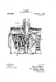
- Figure 1 is a lo itudinal vertical section on the center line 0 the smoke box of a locomotive, showing the invention ap lied;
- the extension pipe 9 passes through and makes close joints with two cylindrical drums or shells 11 and 12, which are concentric with each other and substantially concentric with the smokebox 1.
- the flaring mouth 10 of the draft pipe 9 is within the drum 12, and all gases passing out through the stack 7 are drawn from the interior of the drum 12.
- the exhaust nozzle 8 extends through the walls of the two drums, making close joints therewith and terminating at a point within the inner drum, as clearly indicated in the drawings.
- the outer drum 11 is constructed of sheet metal or plate and at its rear is closed by a conical head 13, also of plate, having its convex side toward the tube sheet.
- the head 13' thus serves as a deflector plate for the gases discharged from the front ends of the boiler tubes, and has a tendency to equalize the draft upon these various tubes.
- the apex of the conical head 13' isin con tact with the tube sheet and this is the usual construction.
- the forward end 14 of the drum 11 and a portion of the sides of the drum adjacent the forward end, as at 15, are constructedof netting or erforated sheet metal or analogous materia so that ases from the boiler tubes first pass around t e drum 11, and then enter through the foraminous portion of the drum.
- the drum is supported in position by wrou ht-iron braces 17, and further b the baffle p ate 18, at its u per side. This p ate 18 extends through 0 a portion of the circumference of the annu ar space intervening between the drum 11 and the smoke box walls 1.
- K second bafile 21 is suspended from the lower side of the drum 11 and extends a part of the radial distance from the drum to the walls of the smoke box 1, and through only a part of the .circumference of the annular space intervening between the drum and the smoke box.
- bafile 18 prevents the passage of gases forward over the top of the drum 11,
- this baffle being adjustable,'while the bafiie 21 being also adjustable may produce any desired restriction ,within a limited range to the flow of gases past the under side of the drum.
- the drum 12 is constructed entirely of foraminous material, with the exception of the front plate 25, which is of sheet metal and is provided with a removable door or cover 26 to permit access to its interior. It
- the drum 12 is partially open at its rear side, the net; ting 29 formlng this portion being inclined inward as at 30 and terminating at a point adjacent the tip of the exhaust nozzle 8. Below this point'the drum is open.
- the products of combustion must pass through the rear portion of the drum 11, and a series of shelves or baffles 31, also of foraminous material intercept and tend to disintegrate any cinders that may be carried by the gases.
- the products of combustion passing through the head 14 of the drum 11 either pass through the sides of the drum 12 or the rear thereof to its interior, and are then drawn up through the extension draft pipe 9 and stack 7 to the atmosphere by the action of the blast from the exhaust nozzle 8.
- the provision of the conical head 13 tends to equalize the draft effect upon the various boiler tubes.
- the shelves 231 are particu- Thus the turcs of the 'two baffle plates permit a. nice adjustment of these plates to the particular locomotive. I
- bafi'les in designing the structure these bafi'les can be proportioned so as to be approximately correct for the particular locomotive, the adjustable feature thus serving to permit variations that actual operation indicates to be desirable.
- the exact proportions indicated in the drawings are given as merely illustrative, and the bafiie 21 as Well as the bafiie 18 may be made to embrace a greater or less proportion of the circumference of the annular space between the drum 11 and the smoke box 1, according to the particular design and requirements of the locomotive.
- each drum having one closed end, the said drums 'being mounted one within another with the closed end of one adjacent the open end of the next and with spaces intervening between their walls to form a sinuous smoke passage from the smoke box to the innermost drum; and a smoke stack adapted to carry in the open ends of said drums; and av smoke stack connected to said innermost chamber.
- drum in said smoke box having one closed end; a screen of foraminous materlal 1n the open end of said drum; baflies of foraminous material upon the interior of the closed end of said drum adapted to receive and disintegrate'the larger cinders; and means for withdrawing smoke from said drum at a point adjacent the baffles.
- 6- The combination of a smoke box; a drum mounted therein closed at its rear end and open at its forward end; a screen of forammous material in the open end of said drum; a second drum within the first ⁇ closed at its forward end and open at its rear end; a screen of foraminous material extendin artially across the open end of said sec0n drum; and a smoke stack connected to said second drum.
- drum mounted therein closed at its rear end 40 andsides and open at its forward end; a screen of foraminou'smaterial, in said 0 n end;'baffles of ,foraniinous materiakwit in said drum at its rear e d; a second within the first closed at its forward .end and second drum.
Landscapes
- Engineering & Computer Science (AREA)
- Mechanical Engineering (AREA)
- General Engineering & Computer Science (AREA)
- Chimneys And Flues (AREA)
Description
G. J. HATZ.
LOGOMOTIVE. v APPLICATION FILED APB..18,1910.
974,486. Patented Nov. 1, 1910.
Z BHBETS-SHBET 1.
a. Q. "OHM G. J. HATZ. LOGOMOTIVB. APPLICATION FILED APILIB, 1910. 974,486. Patented Nov. 1, 1910.
2 SHEETS-SHEET 2.
W I 9 WQoM- I 1% UNITED STATES PATENT OFFICE.
GEORGE J. HATZ, 0F OMAHA, NEBRASKA.
ILocoMo'rIvE.
-To all 407mm it may concern:
Be it known that'I, Gnoncn J. HATZ, a l
citizen of the United States, residin at Omaha, in the county of Douglas and tate of Nebraska, have invented certain new and useful Improvements in Locomotives, of which the following is a specification.
This invention-relates to locomotives, and
'cinders and sparks which are inevitably drawn through the boiler tubes, and the result has been either to discharge such sparks, or cinders in a ,burnin condition, or else to cause their retention in the smoke box unduly, thus necessitating too frequent cleaning or causing the burning out of the smoke box.
By my invention the products of combustion are caused to pursue a circuitous ath in the smokebox with frequent and su den changes 1n direction, so that while the draft of the locomotive is not impaired the cinders [are completely broken up and extinguished prior to their dischar e through the stack.
J A structure embo ying the various features of the invention is illustrated in the drawings, wherein:
Figure 1 is a lo itudinal vertical section on the center line 0 the smoke box of a locomotive, showing the invention ap lied; and
7 is the stack of the locomotive and 8 is the exhaust nozzle, bringing steam from the cylinders. I I
All the above enumerated parts are essentially identical with those in ordinary use on steam locomotives.
- As is usual in locomotive construction, the exhaust nozzle-8 and the stack 7 are alined. In the present construction an extension draft pipe 9is provided which is. connected Specification of Letters'ratent.
Application filed April 18, 1910. Serial No. 556,097.
Patented Nov. 1, 1910.
l with'the stack and extends downward to a point a short distance above the exhaust nozzle 8, and is provided at its lower extremity with a flaring rim 10. This extension pipe 9 passes through and makes close joints with two cylindrical drums or shells 11 and 12, which are concentric with each other and substantially concentric with the smokebox 1. Thus the flaring mouth 10 of the draft pipe 9 is within the drum 12, and all gases passing out through the stack 7 are drawn from the interior of the drum 12. Similarly the exhaust nozzle 8 extends through the walls of the two drums, making close joints therewith and terminating at a point within the inner drum, as clearly indicated in the drawings. The outer drum 11 is constructed of sheet metal or plate and at its rear is closed by a conical head 13, also of plate, having its convex side toward the tube sheet. The head 13' thus serves as a deflector plate for the gases discharged from the front ends of the boiler tubes, and has a tendency to equalize the draft upon these various tubes. In the construction shown the apex of the conical head 13'isin con tact with the tube sheet and this is the usual construction. I
The forward end 14 of the drum 11 and a portion of the sides of the drum adjacent the forward end, as at 15, are constructedof netting or erforated sheet metal or analogous materia so that ases from the boiler tubes first pass around t e drum 11, and then enter through the foraminous portion of the drum. A portion of the end 14L; removably mounted with bolts 16 to give access to the interior of the drum. The drum is supported in position by wrou ht-iron braces 17, and further b the baffle p ate 18, at its u per side. This p ate 18 extends through 0 a portion of the circumference of the annu ar space intervening between the drum 11 and the smoke box walls 1. In order to vary its effect upon the draft it is provided with adjustable extension plates 19, at either side. These plates 19 are held by, the bolts 20 to the baffle plate 18 and may be attached thereto at various positions so as to vary the total Width of this bafile at will. K second bafile 21 is suspended from the lower side of the drum 11 and extends a part of the radial distance from the drum to the walls of the smoke box 1, and through only a part of the .circumference of the annular space intervening between the drum and the smoke box. The
able vertically to vary the extent of the baffle.
Thus the bafile 18 prevents the passage of gases forward over the top of the drum 11,
the circumferential range of this baffle being adjustable,'while the bafiie 21 being also adjustable may produce any desired restriction ,within a limited range to the flow of gases past the under side of the drum.
The drum 12 is constructed entirely of foraminous material, with the exception of the front plate 25, which is of sheet metal and is provided with a removable door or cover 26 to permit access to its interior. It
is supported within the drum 11 in any suitable manner, bolts 27 with distance pieces 28 being indicated in the drawings. The drum 12 is partially open at its rear side, the net; ting 29 formlng this portion being inclined inward as at 30 and terminating at a point adjacent the tip of the exhaust nozzle 8. Below this point'the drum is open. To enter this open portion of the drum, the products of combustion must pass through the rear portion of the drum 11, and a series of shelves or baffles 31, also of foraminous material intercept and tend to disintegrate any cinders that may be carried by the gases. Thus the products of combustion passing through the head 14 of the drum 11, either pass through the sides of the drum 12 or the rear thereof to its interior, and are then drawn up through the extension draft pipe 9 and stack 7 to the atmosphere by the action of the blast from the exhaust nozzle 8.
From the above description it will be ob against various obstructions so that they are rapidly disintegrated and broken up, with the result that by the time they are discharged from the stack they arepractically extinguished, or-if not extinguished so small in size as to burn up before doing any damage. As a result of this action, it is possible to use rather coarse netting and consequently, although the gases pursue a longer course, it is, nevertheless relatively free. draft is not impeded and there is less tendency'for cinders tobe deposited in the smoke I box.
The provision of the conical head 13 tends to equalize the draft effect upon the various boiler tubes. The shelves 231 are particu- Thus the turcs of the 'two baffle plates permit a. nice adjustment of these plates to the particular locomotive. I
it is to be understood that in designing the structure these bafi'les can be proportioned so as to be approximately correct for the particular locomotive, the adjustable feature thus serving to permit variations that actual operation indicates to be desirable. Thus the exact proportions indicated in the drawings are given as merely illustrative, and the bafiie 21 as Well as the bafiie 18 may be made to embrace a greater or less proportion of the circumference of the annular space between the drum 11 and the smoke box 1, according to the particular design and requirements of the locomotive.
Although I have described in detail the various features of the structure it is to be understood that minor variations can of course be made without departing from the spirit of the invention.
Having thus described my invention, what 1. The combination of a smoke box; a
plurality of drums located therein, each drum having one closed end, the said drums 'being mounted one within another with the closed end of one adjacent the open end of the next and with spaces intervening between their walls to form a sinuous smoke passage from the smoke box to the innermost drum; and a smoke stack adapted to carry in the open ends of said drums; and av smoke stack connected to said innermost chamber.
3. The combination of a smoke box; a plurality of drums, located therein, each drum having one closed end; the said drums being mounted one within another with the closed end of'one adjacent the open end of the next, and with spaces intervening between their walls to form a sinuous smoke passage from the smoke. box to the innermost drum; screens of foraminous material in the open ends of said drums; battles of foraminous material in said sinuous passage; and a smoke stack connected to said innermost chamber.
4. The combination of a smoke box; a-plurality of drums, located therein, each drum having one closed end, the said drums being mounted one within another with the closed end of one adj acentthe open end of the next, and with spaces intervening between their the smoke boxto the innermost vdrum;
walls to form a sinuous smoke passage from screens of foraminous material in the open ends of said drums; bafiies of foraminous material in said sinuous passa e; baflie plates within the smoke box an outside said drums; means for adjusting the area of sald bafile plates; and a smoke stack connected to said innermost chamber.
5. The combination of a smoke box, a
drum in said smoke box having one closed end; a screen of foraminous materlal 1n the open end of said drum; baflies of foraminous material upon the interior of the closed end of said drum adapted to receive and disintegrate'the larger cinders; and means for withdrawing smoke from said drum at a point adjacent the baffles.
6-. The combination of a smoke box; a drum mounted therein closed at its rear end and open at its forward end; a screen of forammous material in the open end of said drum; a second drum within the first} closed at its forward end and open at its rear end; a screen of foraminous material extendin artially across the open end of said sec0n drum; and a smoke stack connected to said second drum.
7. The combination of a smoke-box; a
drummounted therein closed at its rear end and sides and open at its forward end; a
screen of foraminous material, in said 0 enend; a second drum within the first close at its forward end and having sides offoraminousmaterial; a screenof foraminous matemal extending partially across the open end of said secon rum; and a'smoke-stack connected to said second drum. 8. The combination of a smoke box; a
drum mounted therein closed at its rear end 40 andsides and open at its forward end; a screen of foraminou'smaterial, in said 0 n end;'baffles of ,foraniinous materiakwit in said drum at its rear e d; a second within the first closed at its forward .end and second drum.
9. The combination of ,a smoke box; 'a drum therein having'its forward end open and its rear-end closed by a conical head adapted to serve as a deflector to gases entering the smoke box; a screen of foraminous 5 material in said open end; a plurality of battles of foraminous material disposed within said drum upon the conical head thereof and adapted to receive and disinte rate the "larger cmdersfand a smoke stack or with ,60
drawing smoke from said drum.
In testimony whereof I have signed my name to this specification in the presence of two subscribing witnesses. V
' GEORGE J. HATZ. Witnesses:
BARTHOLOMEW JULIEN, Commune J. Canny.
Priority Applications (1)
| Application Number | Priority Date | Filing Date | Title |
|---|---|---|---|
| US55609710A US974486A (en) | 1910-04-18 | 1910-04-18 | Locomotive. |
Applications Claiming Priority (1)
| Application Number | Priority Date | Filing Date | Title |
|---|---|---|---|
| US55609710A US974486A (en) | 1910-04-18 | 1910-04-18 | Locomotive. |
Publications (1)
| Publication Number | Publication Date |
|---|---|
| US974486A true US974486A (en) | 1910-11-01 |
Family
ID=3042864
Family Applications (1)
| Application Number | Title | Priority Date | Filing Date |
|---|---|---|---|
| US55609710A Expired - Lifetime US974486A (en) | 1910-04-18 | 1910-04-18 | Locomotive. |
Country Status (1)
| Country | Link |
|---|---|
| US (1) | US974486A (en) |
-
1910
- 1910-04-18 US US55609710A patent/US974486A/en not_active Expired - Lifetime
Similar Documents
| Publication | Publication Date | Title |
|---|---|---|
| US2233613A (en) | Spark arrester | |
| US951994A (en) | Locomotive spark-extinguisher. | |
| US1520956A (en) | Locomotive draft appliance | |
| US238084A (en) | Uthographer | |
| US1060514A (en) | Spark-arrester and draft-regulator for locomotives. | |
| US2163690A (en) | Smoke box arrangement | |
| US1245284A (en) | Draft-regulator and spark-arrester. | |
| US227410A (en) | brown | |
| US1174623A (en) | Locomotive. | |
| US939444A (en) | Spark-arrester. | |
| US225209A (en) | craig | |
| US133984A (en) | Improvement in spark arresters and consumers for locomotives | |
| US2109630A (en) | Locomotive | |
| US978555A (en) | Spark-arrester. | |
| US2226052A (en) | Locomotive smokebox arrangement | |
| US1070174A (en) | Locomotive spark-extinguisher. | |
| US336311A (en) | Territory | |
| US161803A (en) | Improvement in spark-arresters | |
| US546156A (en) | Half to william h | |
| USRE9820E (en) | Said mary | |
| US503501A (en) | smith | |
| US573547A (en) | smith | |
| US1269322A (en) | Locomotive. | |
| US1869891A (en) | Self-cleaning locomotive draft appliance | |
| US746522A (en) | Spark-arrester. |