US9742598B2 - System information convolutional decoding - Google Patents
System information convolutional decoding Download PDFInfo
- Publication number
- US9742598B2 US9742598B2 US14/973,994 US201514973994A US9742598B2 US 9742598 B2 US9742598 B2 US 9742598B2 US 201514973994 A US201514973994 A US 201514973994A US 9742598 B2 US9742598 B2 US 9742598B2
- Authority
- US
- United States
- Prior art keywords
- system information
- encoded
- information packet
- decoded
- decoding
- Prior art date
- Legal status (The legal status is an assumption and is not a legal conclusion. Google has not performed a legal analysis and makes no representation as to the accuracy of the status listed.)
- Expired - Fee Related
Links
Images


Classifications
-
- H—ELECTRICITY
- H04—ELECTRIC COMMUNICATION TECHNIQUE
- H04L—TRANSMISSION OF DIGITAL INFORMATION, e.g. TELEGRAPHIC COMMUNICATION
- H04L1/00—Arrangements for detecting or preventing errors in the information received
- H04L1/004—Arrangements for detecting or preventing errors in the information received by using forward error control
- H04L1/0072—Error control for data other than payload data, e.g. control data
-
- H—ELECTRICITY
- H04—ELECTRIC COMMUNICATION TECHNIQUE
- H04L—TRANSMISSION OF DIGITAL INFORMATION, e.g. TELEGRAPHIC COMMUNICATION
- H04L25/00—Baseband systems
- H04L25/02—Details ; arrangements for supplying electrical power along data transmission lines
- H04L25/03—Shaping networks in transmitter or receiver, e.g. adaptive shaping networks
- H04L25/03006—Arrangements for removing intersymbol interference
- H04L25/03178—Arrangements involving sequence estimation techniques
- H04L25/03248—Arrangements for operating in conjunction with other apparatus
- H04L25/03286—Arrangements for operating in conjunction with other apparatus with channel-decoding circuitry
-
- H—ELECTRICITY
- H03—ELECTRONIC CIRCUITRY
- H03M—CODING; DECODING; CODE CONVERSION IN GENERAL
- H03M13/00—Coding, decoding or code conversion, for error detection or error correction; Coding theory basic assumptions; Coding bounds; Error probability evaluation methods; Channel models; Simulation or testing of codes
- H03M13/37—Decoding methods or techniques, not specific to the particular type of coding provided for in groups H03M13/03 - H03M13/35
- H03M13/39—Sequence estimation, i.e. using statistical methods for the reconstruction of the original codes
- H03M13/41—Sequence estimation, i.e. using statistical methods for the reconstruction of the original codes using the Viterbi algorithm or Viterbi processors
- H03M13/413—Sequence estimation, i.e. using statistical methods for the reconstruction of the original codes using the Viterbi algorithm or Viterbi processors tail biting Viterbi decoding
-
- H—ELECTRICITY
- H04—ELECTRIC COMMUNICATION TECHNIQUE
- H04L—TRANSMISSION OF DIGITAL INFORMATION, e.g. TELEGRAPHIC COMMUNICATION
- H04L1/00—Arrangements for detecting or preventing errors in the information received
- H04L1/004—Arrangements for detecting or preventing errors in the information received by using forward error control
- H04L1/0045—Arrangements at the receiver end
- H04L1/0054—Maximum-likelihood or sequential decoding, e.g. Viterbi, Fano, ZJ algorithms
-
- H—ELECTRICITY
- H04—ELECTRIC COMMUNICATION TECHNIQUE
- H04L—TRANSMISSION OF DIGITAL INFORMATION, e.g. TELEGRAPHIC COMMUNICATION
- H04L1/00—Arrangements for detecting or preventing errors in the information received
- H04L1/004—Arrangements for detecting or preventing errors in the information received by using forward error control
- H04L1/0056—Systems characterized by the type of code used
- H04L1/0059—Convolutional codes
Definitions
- Various embodiments relate generally to mobile communication devices and methods for convolutional Master Information Block (MIB) decoding.
- MIB Master Information Block
- MIMO Master Information Blocks
- PBCH Physical Broadcast Channel
- FIG. 1 shows a bit-level representation of an MIB and an encoded MIB
- FIG. 2 shows a mobile communication network
- FIG. 3 shows an internal configuration of a mobile communication terminal
- FIG. 4 shows a graphical representation of a convolutional encoder
- FIG. 5 shows a trellis diagram representation of a convolutional encoder
- FIG. 6 shows an exemplary path selection in a trellis diagram
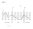
- FIG. 7 shows warm-up region and right extension processing in a trellis diagram
- FIG. 8 shows a method for decoding encoded MIB parity bit sequences
- FIG. 9 shows a graphical representation of a cyclic shift of encoded MIB parity bit sequences
- FIG. 10 shows a first method for decoding system information packets
- FIG. 11 shows a second method for decoding system information packets.
- any phrases explicitly invoking the aforementioned words expressly refers more than one of the said objects.
- references to a “vector” may refer to a vector of any size or orientation, e.g. including a 1 ⁇ 1 vector (e.g. a scalar), a 1 ⁇ M vector (e.g. a row vector), and an M ⁇ 1 vector (e.g. a column vector).
- references to a “matrix” may refer to matrix of any size or orientation, e.g. including a 1 ⁇ 1 matrix (e.g. a scalar), a 1 ⁇ M matrix (e.g. a row vector), and an M ⁇ 1 matrix (e.g. a column vector).
- a 1 ⁇ 1 matrix e.g. a scalar
- a 1 ⁇ M matrix e.g. a row vector
- M ⁇ 1 matrix e.g. a column vector
- a “circuit” as user herein is understood as any kind of logic-implementing entity, which may include special-purpose hardware or a processor executing software.
- a circuit may thus be an analog circuit, digital circuit, mixed-signal circuit, logic circuit, processor, microprocessor, Central Processing Unit (CPU), Graphics Processing Unit (GPU), Digital Signal Processor (DSP), Field Programmable Gate Array (FPGA), integrated circuit, Application Specific Integrated Circuit (ASIC), etc., or any combination thereof. Any other kind of implementation of the respective functions which will be described below in further detail may also be understood as a “circuit”.
- any two (or more) of the circuits detailed herein may be realized as a single circuit with substantially equivalent functionality, and conversely that any single circuit detailed herein may be realized as two (or more) separate circuits with substantially equivalent functionality.
- references to a “circuit” may refer to two or more circuits that collectively form a single circuit.
- memory may be understood as a non-transitory computer-readable medium in which data or information can be stored for retrieval. References to “memory” included herein may thus be understood as referring to volatile or non-volatile memory, including random access memory (RAM), read-only memory (ROM), flash memory, solid-state storage, magnetic tape, hard disk drive, optical drive, etc., or any combination thereof. Furthermore, it is appreciated that registers, shift registers, processor registers, data buffers, etc., are also embraced herein by the term memory. It is appreciated that a single component referred to as “memory” or “a memory” may be composed of more than one different type of memory, and thus may refer to a collective component comprising one or more types of memory.
- any single memory component may be separated into multiple collectively equivalent memory components, and vice versa.
- memory may be depicted as separate from one or more other components (such as in the drawings), it is understood that memory may be integrated within another component, such as on a common integrated chip.
- base station used in reference to an access point of a mobile communication network may be understood as a macro base station, micro base station, Node B, evolved NodeBs (eNB), Home eNodeB, Remote Radio Head (RRH), relay point, etc.
- a “cell” in the context of telecommunications may be understood as a sector served by a base station. Accordingly, a cell may be a set of geographically co-located antennas that correspond to a particular sectorization of a base station. A base station may thus serve one or more cells (or sectors), where each cell is characterized by a distinct communication channel.
- the term “cell” may be utilized to refer to any of a macrocell, microcell, femtocell, picocell, etc.
- radio communication technologies may be classified as one of a Short Range radio communication technology, Metropolitan Area System radio communication technology, or Cellular Wide Area radio communication technology.
- Short Range radio communication technologies include Bluetooth, Wireless Local Area Network (WLAN, e.g. according to any IEEE 802.11 standard), and other similar radio communication technologies.
- Metropolitan Area System radio communication technologies include Worldwide Interoperability for Microwave Access (WiMax) (e.g. according to an IEEE 802.16 radio communication standard, e.g. WiMax fixed or WiMax mobile) and other similar radio communication technologies.
- WiMax Worldwide Interoperability for Microwave Access
- GSM Global System for Mobile Communications
- LTE-A Universal System for Mobile UMTS
- LTE-A LTE-Advanced
- CDMA Wideband Code Division Multiple Access
- WCDMA Long Term Evolution
- LTE-A General Packet Radio Service
- GPRS General Packet Radio Service
- EDGE Enhanced Data Rates for GSM Evolution
- HSPA High Speed Packet Access
- HSPA Plus HSPA+
- network as utilized herein, e.g. in reference to a communication network such as a mobile communication network, encompasses both an access section of a network (e.g. a radio access network (RAN) section) and a core section of a network (e.g. a core network section).
- RAN radio access network
- core network section e.g. a core network section.
- radio idle mode or “radio idle state” used in reference to a mobile terminal refers to a radio control state in which the mobile terminal is not allocated at least one dedicated communication channel of a mobile communication network.
- radio connected mode or “radio connected state” used in reference to a mobile terminal refers to a radio control state in which the mobile terminal is allocated at least one dedicated uplink communication channel of a mobile communication network.
- the term “transmit” encompasses both direct and indirect transmission.
- the term “receive” encompasses both direct and indirect reception unless explicitly specified.
- MTE Long Term Evolution
- PBCH Physical Broadcast Channel
- HARQ Physical Hybrid Automatic Repeat Request
- PHICH Physical Broadcast Channel
- MIB 100 shows a bit-level diagram of MIB 100 , where (from left to right) MIB 100 may contain a downlink system bandwidth field (3 bits), PHICH configuration field (3 bits), System Frame Number (SFN) field (8 bits), spare field (10 bits), and a Cyclic Redundancy Check (CRC) field (16 bits).
- a downlink system bandwidth field (3 bits)
- PHICH configuration field (3 bits)
- SFN System Frame Number
- spare field (10 bits)
- CRC Cyclic Redundancy Check
- a network cell may encode an MIB before transmission, which may provide error-correcting functionality to assist user terminals in accurately identifying the information contained in the MIB.
- 3GPP 3 rd Generation Partnership Project
- TBCC Tail-Biting Convolutional Coding
- a transmitting cell may apply TBCC to the original 40-bit MIB to produce a resulting TBCC-encoded MIB (such as e.g. three 40-bit parity sequences where each MIB bit produces three parity bits (one per 40-bit parity sequence)).
- TBCC Tail-Biting Convolutional Coding
- a user terminal may need to receive and decode an MIB during cell search and selection procedures.
- User terminals may then apply the decoded MIB information to interact with a cell, which may include receiving further system information as part of cell search and selection and subsequently establishing a connection with the cell.
- a user terminal may be able to exploit properties of MIB encoding in order to optimize MIB decoding, in particular for decoding MIBs received from time-synchronized cells.
- a user terminal may be able to identify decoded system information fields of one or more encoded MIBs and apply the decoded system information fields as a priori information to optimize MIB decoding, such as for an initial encoder state of a Viterbi decoder as will be detailed below.
- FIG. 2 shows mobile communication network 200 , which may include mobile terminal 202 and base stations 204 - 208 .
- Each of base stations 204 - 208 may be sectorized to form multiple cells as cells 204 a - 204 c , 206 a - 206 c , and 208 a - 208 c where each cell of base stations 204 - 208 provides a distinct communication channel between a given mobile terminal and the corresponding base station as wireless channels 214 a - 214 c , 216 a - 216 c , and 218 a - 218 c.
- FIG. 3 shows an internal configuration of mobile terminal 202 .
- mobile terminal 202 may include antenna system 302 , radio frequency (RF) transceiver 304 , baseband modem 306 , and application processor 308 .
- RF radio frequency
- mobile terminal 202 may include additional components including hardware, software, or firmware elements such as processors/microprocessors, controllers/microcontrollers, memory, other specialty or generic hardware/processors/circuits, etc., in order to support a variety of additional operations.
- Mobile terminal 202 may also include a variety of user input/output devices (display(s), keypad(s), touchscreen(s), speaker(s), external button(s), camera(s), microphone(s), etc.), peripheral device(s), memory, power supply, external device interface(s), subscriber identify module(s) (SIM), etc.
- display(s) keypad(s), touchscreen(s), speaker(s), external button(s), camera(s), microphone(s), etc.
- peripheral device(s) memory, power supply, external device interface(s), subscriber identify module(s) (SIM), etc.
- SIM subscriber identify module
- mobile terminal 202 may be a mobile communication device including a radio transceiver (RF transceiver 304 ) configured to transmit and receive communication signals, and a baseband modem circuit (baseband modem 306 ) configured to determine a decoded information field of a first encoded system information packet, set one or more bits of the decoded information field as an initial encoder state of a convolutional decoder for decoding the first encoded system information packet, decode the first encoded system information packet with the initial encoder state to obtain a first decoded system information packet, and use the decoded system information packet to transmit or receive data with one or more network cells.
- RF transceiver 304 configured to transmit and receive communication signals
- baseband modem circuit baseband modem 306
- mobile terminal 202 may be a mobile communication device including a radio transceiver configured to receive a plurality of encoded system information packets, and a baseband modem circuit configured to identify a decoded system information field of a first encoded system information packet of the plurality of encoded system information packets, set a decoder state for decoding a second encoded information packet of the plurality of encoded system information packets according to the decoded system information field, and decode the second encoded information packet with the decoder state to obtain a decoded system information packet.
- a radio transceiver configured to receive a plurality of encoded system information packets
- a baseband modem circuit configured to identify a decoded system information field of a first encoded system information packet of the plurality of encoded system information packets, set a decoder state for decoding a second encoded information packet of the plurality of encoded system information packets according to the decoded system information field, and decode the second encoded information packet with the decoder
- RF transceiver 304 may receive radio frequency wireless signals via antenna system 302 , which may be implemented as e.g. a single antenna or an antenna array composed of multiple antennas.
- RF transceiver 304 may include various reception circuitry components, which may include analog circuitry configured to process externally received signals such as e.g. mixing circuity to convert externally received radio frequency signals to baseband and/or intermediate frequencies.
- RF transceiver 304 may also include amplification circuitry to amplify externally received signals, such as power amplifiers (PAs) and/or Low Noise Amplifiers (LNAs), although it is appreciated that such components may also be implemented separately.
- PAs power amplifiers
- LNAs Low Noise Amplifiers
- RF transceiver 304 may additionally include various transmission circuitry components configured to transmit internally received signals, such as e.g. baseband and/or intermediate frequency signals provided by baseband modem 306 , which may include mixing circuitry to modulate internally received signals onto one or more radio frequency carriers and/or amplification circuitry to amplify internally received signals before transmission.
- RF transceiver 304 may provide such signals to antenna system 302 for wireless transmission. Further references herein to reception and/or transmission of wireless signals by mobile terminal 202 may thus be understood as an interaction between antenna system 302 , RF transceiver 304 , and baseband modem 306 as detailed herein.
- Baseband modem 306 may be configured to direct radio communications of mobile terminal 202 . Although the following description may focus on the use of a single radio access technology, it is appreciated that mobile terminal 202 may be configured to operate according to multiple radio access technologies, such where with antenna system 302 , RF transceiver 304 , and/or baseband modem 306 are configured as “multi-mode” components and/or where separate antenna systems, RF transceivers, and/or baseband modems are provided for each supported radio access technology.
- baseband modem 306 may be configured to control wireless communications on an LTE network, and accordingly may be configured to support one or more network connections with one or more network access points (e.g. network cells) according to an LTE protocol stack.
- control circuit 306 c may be a microprocessor or microcontroller configured to retrieve program code (from a memory, not explicitly shown in FIG. 3 ) and execute the program code as protocol stack software and/or firmware modules, which may specify certain protocol stack instructions unique to each layer of the protocol stack.
- Control circuit 306 c may thus be configured to execute various arithmetic, logical, control, and input/output (I/O) operations defined by the protocol stack instructions, and may accordingly maintain one or more network connections over the LTE network.
- I/O input/output
- control circuit 306 c may be configured to retrieve and execute program code as physical layer control software and/or firmware modules, which control circuit 306 c may apply to control physical (PHY) circuit 306 a in accordance with control logic provided by the physical layer control software and/or firmware modules.
- PHY circuit 306 a may thus be configured to perform physical layer processing on signals received from RF transceiver 304 and signals destined for transmission by RF transceiver 304 .
- PHY circuit 306 a may thus be configured to perform various physical layer processing including modulation, equalization, multiplexing, etc., which PHY circuit 306 a may perform upon request by control circuit 306 c .
- control circuit 306 c is depicted as a single component, control circuit 306 c may alternatively be implemented as separate protocol stack and physical layer control circuits.
- PHY circuit 306 a may include decoder circuit 306 b .
- Decoder circuit 306 b may be configured to perform decoding of input signals available at PHY circuit 306 a , such as on signals received from various network access points (via antenna system 302 , RF transceiver 304 , and one or more additional components of PHY circuit 306 a ), and may similarly be controlled via control circuit 306 c .
- decoder circuit 306 b may be configured as a convolutional decoder, such as a Viterbi decoder for decoding TBCC-encoded signals including MIBs.
- PHY circuit 306 a may be composed of multiple circuits including decoder circuit 306 b , where each circuit of PHY circuit 306 a may be configured to perform specific physical layer processing operations.
- Application processor 308 may be implemented as a Central Processing Unit (CPU), and may be configured to execute various applications and/or programs of mobile terminal 202 , such as e.g. applications corresponding to program code stored in a memory component of mobile terminal 202 (not explicitly shown in FIG. 3 ). Application processor 308 may also be configured to control one or more further components of mobile terminal 202 , such as user input/output devices (display(s), keypad(s), touchscreen(s), speaker(s), external button(s), camera(s), microphone(s), etc.), peripheral devices, memory, power supply, external device interfaces, etc.
- CPU Central Processing Unit
- mobile terminal 202 may thus receive an MIB from a cell, such as e.g. cell 204 a , which as previously detailed may have previously been encoded using TBCC by base station 204 .
- the MIB may contain transmission errors in the form of “flipped” binary bits, which may as a result corrupt the MIB information if left uncorrected.
- Baseband modem 306 may accordingly perform TBCC decoding at decoder circuit 306 b on the received encoded MIB in order to correct such errors and recover the original MIB.
- baseband modem 306 may proceed to read further system information received from cell 204 a as System Information Blocks (SIBs), which baseband modem 306 may apply as part of cell search and selection procedures for cell 204 a.
- SIBs System Information Blocks
- the aforementioned transmission errors may be caused by wireless noise and interference.
- Interference from other network cells e.g. transmissions by any of network cells 204 b - 208 c in the exemplary context of FIG. 2
- 3GPP has addressed interference in recent LTE releases such as with enhanced inter-cell interference coordination (eICIC) in Release 10, which is primarily directed towards use in heterogeneous networks with proximate and/or overlapping macro and micro cells.
- eICIC enhanced inter-cell interference coordination
- eICIC systems may utilize “muted” subframes known as Almost Blank Subframes (ABSs) in synchronized cell groups in order to reduce interference between proximate cells, where certain cells may transmit such muted ABSs during pre-mapped subframes to allow other cells to perform transmissions in reduced interference conditions. Accordingly, network cells may be grouped into synchronous cell groups in order to allow for such synchronized transmissions.
- ABSs Almost Blank Subframes
- ABSs While the use of ABSs may reduce interference, ABSs may not be completely muted and accordingly may still contain certain essential signals. Specifically, network cells performing ABS transmission during a given subframe may still transmit cell-specific reference signals (CRSs), Primary and Secondary Synchronization Signals (PSS and SSS), and PBCH data, which may be needed to ensure that early Release 8 or 9 compliant devices are still supported. Accordingly, a user terminal receiving a signal from a network cell performing ABS transmission may need to decode such signals in hostile interference scenarios.
- CRSs cell-specific reference signals
- PSS and SSS Primary and Secondary Synchronization Signals
- PBCH data which may be needed to ensure that early Release 8 or 9 compliant devices are still supported. Accordingly, a user terminal receiving a signal from a network cell performing ABS transmission may need to decode such signals in hostile interference scenarios.
- the aforementioned MIB reception and decoding on the PBCH may require advanced receiver processing in order to suppress the interference of “aggressor cells” in order to allow a user terminal to decode PBCH data (MIB) from a “victim cell”.
- User terminals may need to perform multiple detection attempts on the same received PBCH data in order to sufficiently remove interference to allow for PBCH decoding, which may include performing Successive Interference Cancelation (SIC).
- SIC Successive Interference Cancelation
- a receiver may receive a composite signal containing one or more conflicting signals.
- a receiver may then detect and reconstruct the strongest conflicting signal before subsequently canceling the strongest conflicting signal from the composite signal to obtain a composite residue signal that contains the remaining conflicting signals (minus the strongest conflicting signal).
- a receiver may iteratively repeat this process to subsequently detect and recover each conflicting signal.
- a user terminal employing SIC to detect an MIB from a network cell may need to iteratively cancel conflicting signals from the other proximate cells in order to recover the desired MIB.
- a user terminal receiving an MIB may need to cancel conflicting MIBs transmitted simultaneously by other synchronized conflicting cells in order to recover the desired MIB.
- a user terminal may therefore successively cancel multiple received conflicting MIBs from a received composite signal during SIC, and thus may be able to recover and decode an MIB from the strongest conflicting cell during the first SIC iteration.
- each MIB will be synchronized in time and contain an identical SFN field in MIB bits 6 - 13 as shown in FIG. 1 .
- a user terminal may utilize such “common” information between multiple MIBs in order to improve decoding of the remaining synchronized MIBs.
- a user terminal such as mobile terminal 202 may utilize the common SFN field identified during the first SIC iteration as a priori information to initialize an MIB decoder. By doing so, mobile terminal 202 may obtain improve decoding accuracy and reduce the computational expenditure required to decode MIBs, in particular for the latter SIC iterations.
- Mobile terminal 202 may exploit a unique “circular” property of TBCC encoding to apply the identified SFN in such a manner.
- an encoder may utilize an input bit sequence to produce a sequence of parity bits as an output.
- the encoder may internally hold a certain number of recent input bits at any given time as the “state” of the encoder (e.g. in one or more shift registers), where each encoder state will produce a specific parity bit output given a 0 or a 1 as the next input bit (assuming a single input bit per parity bit output stage).
- the number of input bits held as the encoder state is defined by the “constraint length” K, where the K ⁇ 1 most recent past input bits define the encoder state at any point in time. Each of these past input bits held as the encoder state in addition to the next input bit of the input sequence will thus determine the parity bits output by the encoder.
- An encoder may output more than one parity bit per input bit, and accordingly may produce multiple parity bit sequences.
- convolutional encoder 400 may calculate each parity bit by performing an XOR operation with the encoder state bits m ⁇ 1 and m ⁇ 2 (the most recent two input bits of the input sequence) and the current input bit m 0 (the next input bit of the input sequence). As shown in FIG.
- Each of m 0 , m ⁇ 1 , and m ⁇ 2 may shift to the right following each parity output (i.e. each set of parity bits output), where m ⁇ 2 is discarded, m ⁇ 1 moves to m ⁇ 2 , m 0 moves to m ⁇ 1 , and the input sequence provides the next input bit as m 0 .
- Convolutional encoder 400 may then calculate the next parity bits based on the “new” encoder state (m ⁇ 1 m ⁇ 2 ) and “new” input bit m 0 . Convolutional encoder 400 may thus output two parity bit sequences, where each corresponding pair of parity bits in the two parity bit sequences corresponds to a common input bit.
- the encoder state (m ⁇ 1 m ⁇ 2 ) may vary over time depending on the input bits provided from the input sequence, where the encoder state may undergo “state transitions” as the state changes according to each sequential input bit.
- the state transitions and state paths of convolutional encoders may be temporally represented by a trellis diagram as depicted by trellis diagram 500 as depicted in FIG. 5 .
- Each numerically labeled circle in trellis diagram 500 may represent an encoder state (m ⁇ 1 m ⁇ 2 ) of convolutional encoder 400 .
- Trellis diagram 500 thus depicts each possible state transition of convolutional encoder 400 over time, and accordingly also depicts the possible valid state transitions and state paths of convolutional encoder 400 .
- the set of parity bit outputs over time may thus be the parity bit sequences output by convolutional encoder 400 , which in the case of convolutional coder 400 may be two parity bit sequences—a first parity bit sequence for the n 1 parity bits and a second parity bit sequence for the n 2 parity bits.
- Convolutional encoder 400 may thus produce one or more sequences of parity bits for a given input sequence, where convolutional encoder 400 may undergo a series of state transitions corresponding to the input sequence and the produced parity bit sequence.
- the parameters of convolutional encoder 400 detailed herein are exemplary, and accordingly numerous other convolutional encoders may be realized using different constraint lengths, input size (i.e. the number of simultaneous input bits), output size (i.e. the number of simultaneous parity bits outputted), parity generator polynomials, etc.
- base station 204 may encode original MIB 100 to produce encoded MIB parity big sequences 110 a - 110 c .
- encoded MIB parity big sequences 110 a - 110 c may be a set of three parity bit sequences ( 110 a , 110 b , and 110 c ) each 40 bits in length, where the parity bits with corresponding positions in each the three parity bit sequences correspond to the same input bit of original MIB 100 as depicted in FIG. 1 .
- encoded MIB parity bit sequences 110 a - 110 c as received by mobile terminal 202 may contain error, which mobile terminal 202 may correct during decoding of encoded MIB parity bit sequences 110 a - 110 c to recover original MIB 100 .
- Mobile terminal 202 may apply a Viterbi decoder in order to decode encoded MIB parity bit sequences 110 a - 110 c to recover original MIB 100 , such as where decoder circuit 306 b is realized as a Viterbi decoder circuit.
- Viterbi decoders may operate on one or more parity bit sequence, e.g. encoded MIB parity bit sequences 110 a - 110 c , in order to determine the most likely encoder state path (i.e. the sequence of encoder state transitions) of the convolutional encoder that produced the parity bit sequences. By determining the most likely encoder state path, a Viterbi decoder may determine each input bit (as each input bit produces a specific state transition for each encoder state) corresponding to the most likely encoder state path and accordingly recover a valid input sequence, e.g. original MIB 100 .
- a Viterbi decoder may determine each input bit (as each input bit produces a specific state transition for each encoder state) corresponding to the most likely encoder state path and accordingly recover a valid input sequence, e.g. original MIB 100 .
- a Viterbi decoder may be able to correct bit errors by identifying a valid state path that has the highest probabilistic match with the received parity bit sequences (which may not exactly match with a valid state path due to bit errors).
- a Viterbi decoder may “trace back” through the trellis in a “traceback procedure” to determine the input bit sequence that produced the most likely encoder state path, and accordingly may obtain an input bit sequence that probabilistically matches with the original input bit sequence.
- bit errors in the received parity bit sequences may produce “mismatches” with the valid parity bit outputs for each encoder state.
- certain encoder state transitions may be characterized as having a certain level of error (i.e. depending on how many bits of the received parity bit sequences do not match the parity output bits of the encoder state transition), and accordingly a hypothetical encoder state path that contains encoder state transitions having errors may additionally be characterized as having a certain level of error that is collectively representative of the errors of each encoder state transition of the encoder state path.
- a Viterbi decoder may utilize state transition error (quantified as a “branch metric”) in order to identify state paths with low error (quantified as a “path metric”), and may utilize analysis of “future” encoder states to make state transition selections from “past” encoder states.
- the Viterbi decoder may not be able to select which state transition is part of the most likely state path. The Viterbi decoder may thus proceed to evaluate the parity outputs from the (00) and (10) encoder states to determine whether either the (00) or (10) encoder states produce parity bits outputs that closely match the received parity bit sequences. As shown in 610 , the (00) ⁇ (00) transition may produce a parity bit output with 0 error (i.e. that matches the received parity bit sequences), while the other transitions ((00) ⁇ (10), (10) ⁇ (01), and (10) ⁇ (11)) may produce at least 1 or greater error.
- the Viterbi decoder may select 610 as part of the most likely encoder state path. Accordingly, the comparison of the parity bits output from “future” encoder states with the received bit sequence may allow the Viterbi decoder to make accurate state path selections, which may be utilized in TBCC coding as will be later detailed.
- a Viterbi decoder may thus attempt to determine the encoder state path that has the least error (lowest path metric), i.e. the sequence of encoder state transitions that produces a parity bit sequences (according to the parity generator polynomials) that most closely matches the received parity bit sequences.
- a Viterbi decoder may additionally be able to correct errors during recovery of the original input bit sequence, e.g. original MIB 100 .
- the specifics of such Viterbi decoders, both for hard and soft decoding, are well-established and will be recognized by skilled persons.
- the initial encoder state may not be known at the decoder.
- each possible encoder state e.g. (00), (01), (10), and (11)
- a Viterbi decoder may independently assume that each possible encoder state is the initial encoder state and determine a most likely encoder state path starting from each possible encoder state.
- One or more of these candidate encoder state paths may converge into a single encoder state path, i.e. where two or more candidate encoder state paths meet at a single encoder state on the trellis and subsequently proceed along the same encoder state path as all candidate encoder state paths are analyzed using the same received parity bit sequences.
- a Viterbi decoder may subsequently arrive at one or more remaining “survivor” paths, and may select the survivor path with the highest probability (i.e. that produces parity bit sequences that matches the received parity bit sequences with the lowest error) as the final encoder state path.
- a Viterbi decoder may identify the corresponding input bits (that trigger each state transition in the final encoder state path) to recover the original input sequence as part of the “traceback” procedure.
- a conventional Viterbi decoder may need to independently evaluate encoder state paths from each possible encoder state as the initial encoder state. Such may include evaluating state paths from each of the 2 K-1 possible encoder states, which may involve executing 2 K-1 independent Viterbi decoder algorithms (one per possible starting encoder state, in serial or parallel) which has an inherently high processing cost.
- ZTCC Zero-Tailed Convolutional Coding
- TBCC Tail-Biting Convolutional Coding
- the encoder may set the initial encoder state of the encoder to zero (e.g.
- the encoder may ensure that the initial and final encoder state is the same, but not necessarily both the zero state.
- TBCC encoders may ensure matching initial and final encoder states by setting the initial K ⁇ 1-bit encoder state to match the final K ⁇ 1 bits of the input sequence (thus additionally requiring that the entire input sequence is known at the start of encoding in order to initialize the encoder state). As no extra bits are added by the encoder to force a final encoder state, TBCC may not result in a rate reduction.
- a TBCC decoder may not have exact knowledge of the initial and final encoder states and may instead only assume that the initial and final states are the same. Thus, the uniform likelihood assumption of all initial encoder states may still hold.
- Viterbi decoders may exploit this cyclic nature of TBCC-encoded parity bit sequences in order to effectively perform decoding using the matching initial-final encoder state assumption. Specifically, a Viterbi decoder may cyclically “repeat” the received parity bit sequences and perform Viterbi decoding over the repeated received parity bit sequences as a “warm-up region” (or “left extension”) in order to arrive at a likely initial encoder state at the beginning of the received parity bit sequences (where the warm-up region may be e.g. 5 times the constraint length in order to obtain convergence to the initial encoder state).
- the Viterbi decoder may decode from starting point 710 of the warm-up region (selected depending on the warm-up region length) to the ending point 720 of the warm-up region, which may include independent decoding from each possible encoder state over the warm-up region until eventually reaching the beginning of the received parity bit sequences 720 at the end of the warm-up region.
- the Viterbi decoder may be able to identify a likely initial encoder state of the received parity bit sequences corresponding to a survivor path of the warm-up region (due to path convergence and/or path metric comparisons). The Viterbi decoder may then utilize this likely initial encoder state from the warm-up region for decoding of the received parity bit sequences starting at 720 .
- Various different specific procedures may be available for selection of the warm-up region and application of the likely initial encoder state, which may vary dependent on the number of traceback lengths contained in the input sequence.
- a Viterbi decoder may utilize the likely initial encoder state for selection of the most likely encoder state path, as only encoder state paths that have matching initial and final encoder states are considered valid.
- a Viterbi decoder decoding a TBCC parity bit sequences may employ a “right extension” (as shown in FIG. 7 ) by similarly decoding cyclically shifted copies of the received parity bit sequences following the end of the received parity bit sequences at 730 .
- Viterbi decoders may rely on comparisons of parity bit outputs from “future” encoder states to decide on state transitions of “past” encoder states along the state path, and thus may utilize the right extension in order to ensure the accuracy of the final encoder state of the one or more surviving paths of the received parity bit sequences.
- Viterbi decoders may decode TBCC-encoded parity bit sequences using warm-up regions and right extensions in order to identify survivor paths having matching initial and final encoder states.
- the encoder may not need to insert extra bits into the parity bit sequences (as is the case of ZTCC encoding)
- the coding rate of TBCC may not be negatively impacted.
- a Viterbi decoder may need to perform extra processing in the form of warm-up region and right extension processing in order to exploit the encoder state constraints of TBCC encoding.
- mobile terminal 202 may receive encoded MIB parity bit sequences 110 a - 110 c from cell 204 a of base station 204 over wireless channel 214 a , which may be corrupted as a result of wireless transmission. Mobile terminal 202 may thus be required to perform TBCC decoding on encoded MIB parity bit sequences 110 a - 110 c , such as with a Viterbi decoder, in order to recover original MIB 100 .
- mobile terminal 202 may in particular utilize the 8-bit SFN field (MIB bits 6 - 13 ), and accordingly may identify the SFN field and subsequently utilize the SFN field as an initial encoder state during Viterbi decoding. As mobile terminal 202 may thus be able to identify an accurate initial encoder state, mobile terminal 202 may not need to perform any warm-up region or right extension processing and may instead utilize perfect information to initialize the decoder.
- MIB bits 6 - 13 8-bit SFN field
- mobile terminal 202 may not need to perform any warm-up region or right extension processing and may instead utilize perfect information to initialize the decoder.
- mobile terminal 202 may receive wireless radio frequency signals via antenna system 302 , which may be subsequently processed by RF transceiver 304 and PHY circuit 306 a under the direction of control circuit 306 c .
- PHY circuit 306 a may thus encoded MIB parity bit sequences 110 a - 110 c by way of such processing and may provide encoded MIB parity bit sequences 110 a - 110 c to decoder circuit 306 b for convolutional decoding.
- Decoder circuit 306 b may be configured to perform Viterbi decoding on encoded MIB parity bit sequences 110 a - 110 c in order to recover the original MIB.
- the various physical realizations of Viterbi decoders both in the form of hardware and software executed by a processor, are established and will be appreciated by skilled persons.
- FIG. 8 shows method 800 for decoding TBCC-encoded MIB sequences, which decoder circuit 306 b may employ on a TBCC-encoded MIB sequence.
- decoder circuit 306 b may first receive encoded MIB parity bit sequences 110 a - 110 c at 810 .
- mobile terminal 202 may receive encoded MIB parity bit sequences 110 a - 110 c via antenna system 302 as part of a received wireless signal and process the received wireless signal at RF transceiver 304 and PHY circuit 306 a to obtain encoded MIB parity bit sequences 110 a - 110 c at decoder circuit 306 b .
- Decoder circuit 306 b may then determine the SFN value contained in original MIB 100 , which may be contained in MIB bits 6 - 13 as shown in FIG. 1 .
- mobile terminal 202 may perform MIB decoding during hostile interference scenarios where multiple synchronized cells perform simultaneous MIB PBCH transmission.
- mobile terminal 202 may receive encoded MIB parity bit sequences 110 a - 110 c in 810 from network cell 204 a as part of a composite wireless signal that additionally contains TBCC-encoded MIB sequences from e.g. network cells 206 b and 208 c , where network cells 204 a , 206 b , and 208 c may form a synchronous cell group.
- mobile terminal 202 may simultaneously receive parity bit sequences from each of network cells 204 a , 206 b , and 208 c , e.g. three encoded MIB parity bit sequences for each of network cells 204 a , 206 b , and 208 c (e.g. nine total) as the “composite” encoded MIB parity bit sequences.
- mobile terminal 202 may utilize the SFN field of the corresponding original MIB as a priori information to initialize decoding, i.e. as the initial encoder state for decoding, of the composite encoded MIB parity bit sequences.
- mobile terminal 202 may not initially know the SFN field of any of the composite encoded MIB parity bit sequences, mobile terminal 202 may need to perform a “full” decode of at least one of the composite encoded MIB parity bit sequences, which may include warm-up region and right extension processing to obtain accurate initial and final encoder states as detailed above regarding Viterbi TBCC decoding.
- mobile terminal 202 may perform an SIC procedure in order to isolate the individual encoded MIB parity bit sequences of each of network cells 204 a , 206 b , and 208 c from the composite encoded MIB parity bit sequences.
- PHY circuit 306 a may perform such an SIC procedure in order to iteratively isolate each of the conflicting signals, where the details of such SIC procedures will be appreciated by skilled persons.
- mobile terminal 202 may isolate the encoded MIB parity bit sequences from one of network cells 204 a , 206 b , and 208 c , such as e.g. the encoded MIB parity bit sequences from network cell 206 b .
- Decoder circuit 306 b may then perform a full Viterbi TBCC decode on the encoded MIB parity bit sequences of network cell 206 b (represented as encoded MIB parity bit sequences 110 a - 110 c ), and accordingly may obtain the original MIB including each of the downlink bandwidth, PHICH configuration, SFN, spare, and CRC fields of the original MIB (represented as original MIB 100 ).
- decoder circuit 306 b may assume that the SFN field of each of the original MIBs is identical, i.e. the composite encoded MIB parity bit sequences correspond to a original MIBs with a common SFN field. Decoding circuit 306 b may thus identify the common SFN field in 820 in a first SIC iteration by decoding the encoded MIB parity bit sequences from a first cell to recover the original MIB, e.g.
- Decoder circuit 306 b may then subsequently employ the identified SFN as the initial encoder state to perform Viterbi decoding on the remaining encoded MIB parity bit sequences of the composite encoded MIB parity bit sequences, e.g. for network cells 204 a and 208 c.
- TBCC-encoded parity bit sequences and the corresponding encoder states may be considered “circular” or “cyclical” due to the common initial and final states. Accordingly, this circularity holds for all cyclic shifts of a TBCC-encoded parity bit sequence; in other words, a TBCC-encoded parity bit sequence may be shifted according to any possible cyclic shift and will produce matching initial and final encoder states for a subsequent decode of the cyclically shifted TBCC-encoded parity bit sequence. Furthermore, as previously detailed a TBCC encoder may obtain matching initial and final encoder states by initializing the encoder state to match the final K ⁇ 1 bits of the input sequence.
- decoding circuit 306 b may isolate a second set of encoded MIB parity bit sequences corresponding to another cell, e.g. network cell 204 a , from the composite encoded MIB parity bit sequences in a second SIC iteration.
- decoder circuit 306 b may first preprocess the encoded MIB parity bit sequences by cyclically shifting the encoded MIB parity bit sequences in 830 .
- decoder circuit 306 b may cyclically shift the encoded MIB parity bit sequences to position the SFN field (MIB bits 6 - 13 ) at the end of the encoded MIB parity bit sequences, thus causing the cyclically-shifted encoded MIB parity bit sequences to have an initial encoder state equal to the SFN field due to the cyclic nature of TBCC codes.
- FIG. 9 depicts a graphical illustration of such a cyclic shift, where decoding circuit 306 b may cyclically shift encoded MIB parity bit sequences 900 a - c (e.g.
- decoder circuit 306 b may employ any 6 consecutive bits of the identified SFN field as the initial encoder state, and cyclically shift the encoded MIB parity bit sequences accordingly.
- the cyclic shift of FIG. 9 depicts an implementation in which decoding circuit 306 b utilizes the 6 Most Significant Bits (MSBs) of the SFN field as the initial encoder state.
- MSBs Most Significant Bits
- decoder circuit 306 b may then perform Viterbi TBCC decoding on the cyclically shifted encoded MIB parity bit sequences with the selected consecutive 6 bits of the SFN field as the initial encoder state. As decoding circuit 306 b determined the SFN field in 820 from a previously MIB decode procedure of a synchronized cell, decoder circuit 306 b may thus be able to perform the Viterbi TBCC decode with perfect initial and final encoder states. Decoder circuit 306 b may thus be able to perform both forward search and traceback with perfect information in 830 , and accordingly may obtain superior performance without needing to perform any extra processing in the form of warmup region or right extension processing.
- decoder circuit 306 b may then repeat 830 and 840 on any remaining encoded MIB parity bit sequences of the composite encoded MIB parity bit sequences, e.g. the encoded MIB parity bit sequences received from network cell 208 c . Decoder circuit 306 b may similarly apply the SFN field identified from the full decode of the encoded MIB parity bit sequences of network cell 206 b in 820 in order to initialize the 6-bit encoder state for Viterbi decoding and cyclically shift the encoded MIB parity bit sequences of network cell 208 c accordingly.
- Method 800 may thus be particularly applicable in the event of SIC procedures for PBCH decoding from synchronous cells that simultaneously transmit MIBs with a common SFN field.
- decoder circuit 306 b may perform a full decode of encoded MIB parity bit sequences received from a first network cell and subsequently utilize the identified SFN field as the initial encoder state to decode encoded MIB parity bit sequences received from a second network cell synchronized with the first network cell (and e.g. a third synchronized network cell, a fourth synchronized network cell, etc.).
- decoder circuit 306 b may equivalently employ method 800 to decode multiple synchronized encoded MIB parity bit sequences for any two or more cells that transmit synchronized MIBs. It is also noted that user terminals may be able to determine the SFN field of a set of encoded MIB parity bit sequences by other mechanisms, such as based on a previous connection to a particular cell or a previous connection to any cell in a synchronous cell group. Accordingly, decoding circuit 306 b may implement method 800 regardless of the exact procedure used to determine the SFN field of the encoded MIB parity bit sequences in 820 .
- decoder circuit 306 b may be able to utilize an MIB field other than the SFN field as the consecutive 6-bit initial encoder state if such information is available.
- decoder circuit 306 b may have previous knowledge of the downlink bandwidth and PHICH configuration of a particular network cell, such as based on a previous connection to the network cell.
- decoder circuit 306 b may identify the downlink bandwidth (MIB bits 0 - 2 ) and PHICH configuration (MIB bits 3 - 5 ) and apply the 6-bit combined downlink bandwidth and PHICH configuration fields (e.g. MIB bits 0 - 5 ) as the initial encoder state for Viterbi decoding, which may not require a cyclic shift operation due to the initial positioning of the downlink bandwidth field within the MIB.
- MIB bits 0 - 2 downlink bandwidth
- PHICH configuration MIB bits 3 - 5
- a “partial” initial encoder state for Viterbi decoding such as if decoder circuit 306 b has knowledge of less than 6 consecutive bits.
- PHY circuit 306 a may provide the decoded MIB information to control circuit 306 c , which may proceed to manage wireless communication operations of mobile terminal 202 based on the decoded MIB information. For example, PHY circuit 306 a may provide MIB information to control circuit 306 c for each network cell that provides a set of encoded MIB parity bit sequences that is decoded by decoding circuit 306 a . Control circuit 306 c may then further interact with each network cell based on the decoded MIB information, which may include receiving additional system information (e.g. SIB1 and SIB2) from each network cell as part of a cell search procedure and subsequently selecting (or re-selecting) a serving cell based on the system information and/or cell measurements.
- additional system information e.g. SIB1 and SIB2
- Decoding circuit 306 b may repeat method 800 during each occasion that mobile terminal 202 performs MIB detection, which may be controlled and triggered by control circuit 306 c according to control logic of the protocol stack executed by control circuit 306 c.
- FIG. 10 shows a flow chart illustrating method 1000 of decoding system information packets.
- method 1000 includes determining a decoded information field of a first encoded system information packet; setting one or more bits of the decoded information field as an initial encoder state of a convolutional decoder for decoding the first encoded system information packet; decoding the first encoded system information packet with the initial encoder state to obtain a first decoded system information packet; and applying the decoded system information packet to transmit or receive data with one or more network cells.
- method 1000 may be further incorporated into method 1000 .
- method 1000 may be configured to perform further and/or alternate processes as detailed regarding mobile terminal 202 , RF transceiver 304 , and/or baseband modem 306 .
- FIG. 11 shows a flow chart illustrating method 1100 of decoding system information.
- method 1100 includes receiving a plurality of encoded system information packets of a first type, identifying a decoded system information field of a first encoded system information packet of the plurality of encoded system information packets, setting a decoder state for decoding a second encoded information packet of the plurality of encoded system information packets according to the decoded system information field, and decoding the second encoded information packet with the decoder state to obtain a decoded system information packet.
- method 1100 may be further incorporated into method 1100 .
- method 1100 may be configured to perform further and/or alternate processes as detailed regarding mobile terminal 202 , RF transceiver 304 , and/or baseband modem 306 .
- a mobile terminal may optimize decoding of TBCC-encoded MIB parity bit sequences by identifying bits of the original MIB and apply the identified bits of the original MIB as a priori information to initialize a decoder state, e.g. the assumed initial encoder state during Viterbi decoding.
- a mobile terminal may apply any bits of the original MIB and perform an appropriate cyclic shift of the encoded MIB parity bit sequences to begin decoding at a point in the encoded MIB parity bit sequences having the initial encoder state.
- Such may be particularly applicable in MIB decoding for synchronized cells, where a mobile terminal may identify the common SFN field by decoding the MIB for a first cell of the synchronized cells (e.g. during a first SIC iteration) and applying the common SFN field as the initial encoder state to decode MIBs for the remaining synchronized cells.
- a mobile terminal may initialize a Viterbi decoder for MIB decoding using any identified bits of the original MIB, which may even include “partial” initial encoder states.
- a mobile terminal may thus improve the accuracy of Viterbi decoding from the use of perfect information and reduce extra processing, such as for warm-up regions and right extensions.
- UE user equipment
- mobile terminal may apply to any wireless communication device, including cellular phones, tablets, laptops, personal computers, wearables, multimedia playback devices, consumer/home appliances, vehicles, etc., and any number of additional electronic devices capable of wireless communications.
- Example 1 is a method for decoding system information packets, the method including determining a decoded information field of a first encoded system information packet, setting one or more bits of the decoded information field as an initial encoder state of a convolutional decoder for decoding the first encoded system information packet, decoding the first encoded system information packet with the initial encoder state to obtain a first decoded system information packet, and using the decoded system information packet to transmit or receive data with one or more network cells.
- Example 2 the subject matter of Example 1 can optionally include wherein the decoding the first encoded system information packet with the initial encoder state to obtain a first decoded system information packet includes sequentially decoding the first encoded system information packet starting with the initial encoder state.
- Example 3 the subject matter of Example 1 can optionally include wherein the decoding the first encoded system information packet with the initial encoder state to obtain a first decoded system information packet includes sequentially decoding the first encoded system information packet using Viterbi decoding starting with the initial encoder state.
- Example 4 the subject matter of Example 2 or 3 can optionally further include circularly shifting the first encoded system information packet according to the initial encoder state.
- Example 5 the subject matter of any one of Examples 1 to 4 can optionally further include receiving a plurality of encoded system information packets including the first encoded system information packet.
- Example 6 the subject matter of Example 5 can optionally include wherein the receiving a plurality of encoded system information packets including the first encoded system information packet includes simultaneously receiving the plurality of encoded system information packets from a plurality of synchronized network cells.
- Example 7 the subject matter of Example 5 or 6 can optionally include wherein the plurality of encoded system information packets include the same system information packet type.
- Example 8 the subject matter of any one of Examples 5 to 7 can optionally include wherein the plurality of encoded system information packets are encoded Master Information Blocks (MIBs).
- MIBs Master Information Blocks
- Example 9 the subject matter of any one of Examples 5 to 8 can optionally include wherein each of the plurality of encoded system information packets contain the decoded system information field.
- Example 10 the subject matter of any one of Examples 5 to 9 can optionally include wherein the determining a decoded information field of a first encoded system information packet includes decoding a second encoded system information packet of the plurality of encoded system information packets to obtain a second decoded system information packet, wherein the decoded information field is an information field of the second decoded system information packet.
- Example 11 the subject matter of Example 10 can optionally include wherein the decoding a second encoded system information packet of the plurality of encoded system information packets to obtain a second decoded system information packet includes decoding the second encoded system information packet during a first interference cancelation iteration, and wherein the decoding the first encoded system information packet with the initial encoder state to obtain a first decoded system information packet includes decoding the first encoded system information packet during a second interference cancelation iteration occurring after the first interference cancelation iteration.
- Example 12 the subject matter of Example 11 can optionally include wherein the first interference cancelation iteration and the second interference cancelation iteration are stages of a Successive Interference Cancelation (SIC) procedure.
- SIC Successive Interference Cancelation
- Example 13 the subject matter of any one of Examples 10 to 12 can optionally include wherein the receiving a plurality of encoded system information packets including the first encoded system information packet includes receiving the plurality of encoded system information packets from a plurality of network cells.
- Example 14 the subject matter of Example 13 can optionally include wherein the plurality of network cells are a plurality of synchronized network cells.
- Example 15 the subject matter of any one of Examples 10 to 12 can optionally include wherein the receiving a plurality of encoded system information packets including the first encoded system information packet includes receiving the plurality of encoded system information packets from a plurality of synchronized network cells.
- Example 6 the subject matter of any one of Examples 1 to 15 can optionally further include performing a circular shift of the first encoded system information packet, and wherein the decoding the first encoded system information packet with the initial encoder state to obtain a first decoded system information packet includes decoding the circularly-shifted first encoded system information packet with the initial encoder state to obtain the first decoded system information packet.
- Example 7 the subject matter of any one of Examples 1 to 16 can optionally include wherein the decoding the first encoded system information packet with the initial encoder state to obtain a first decoded system information packet includes decoding the first encoded system information packet using Viterbi decoding with the initial encoder state.
- Example 18 the subject matter of any one of Examples 1 to 17 can optionally include wherein the first encoded system information packet is a Tail-Biting Convolutional Code (TBCC)-encoded system information packet.
- TBCC Tail-Biting Convolutional Code
- Example 19 the subject matter of any one of Examples 1 to 18 can optionally include wherein the decoded information field is a System Frame Number (SFN) field.
- SFN System Frame Number
- Example 20 the subject matter of any one of Examples 1 to 19 can optionally include wherein the first encoded system information packet is a convolutional encoded system information packet.
- Example 21 the subject matter of any one of Examples 1 to 20 can optionally include wherein the using the decoded system information packet to transmit or receive data with one or more network cells includes performing cell search or selection with information of the decoded system information packet.
- Example 22 the subject matter of any one of Examples 1 to 20 can optionally include wherein the first encoded system information packet is an encoded Master Information Block (MIB).
- MIB Master Information Block
- Example 23 is a communication circuit configured to perform the method of any one of Examples 1 to 22.
- Example 24 is a mobile communication device including a radio transceiver and a communication circuit configured to interact with the radio transceiver to transmit and receive radio signals, the communication circuit configured to perform the method of any one of Examples 1 to 22.
- Example 25 is a non-transitory computer readable medium storing instructions that when executed by a processor cause the processor to perform the method of any one of Examples 1 to 22.
- Example 26 is a method for decoding system information packets, the method including receiving a plurality of encoded system information packets, identifying a decoded system information field of a first encoded system information packet of the plurality of encoded system information packets, setting a decoder state for decoding a second encoded information packet of the plurality of encoded system information packets according to the decoded system information field, and decoding the second encoded information packet with the decoder state to obtain a decoded system information packet.
- Example 27 the subject matter of Example 26 can optionally include wherein the receiving a plurality of encoded system information packets includes simultaneously receiving the plurality of encoded system information packets from a plurality of synchronized network cells.
- Example 28 the subject matter of Example 26 or 27 can optionally further include using the decoded system information packet to transmit or receive data with one or more network cells.
- Example 29 the subject matter of Example 26 or 27 can optionally further include performing cell search or selection with information contained in the decoded system information packet.
- Example 30 the subject matter of any one of Examples 26 to 29 can optionally include wherein the plurality of encoded system information packets include the same system information packet type.
- Example 31 the subject matter of any one of Examples 26 to 30 can optionally include wherein the decoding the second encoded information packet with the decoder state to obtain a decoded system information packet includes sequentially decoding the second encoded information packet starting with the initial encoder state.
- Example 32 the subject matter of any one of Examples 26 to 30 can optionally include wherein the decoding the second encoded information packet with the decoder state to obtain a decoded system information packet includes sequentially decoding the first encoded system information packet starting using Viterbi decoding with the initial encoder state.
- Example 33 the subject matter of Example 31 or 32 can optionally further include circularly shifting the first encoded system information packet according to the initial encoder state.
- Example 34 the subject matter of any one of Examples 26 to 33 can optionally include wherein the plurality of encoded system information packets are encoded Master Information Block (MIBs).
- MIBs Master Information Block
- Example 35 the subject matter of any one of Examples 26 to 34 can optionally include wherein each of the plurality of encoded system information packets contain the decoded system information field.
- Example 36 the subject matter of any one of Examples 26 to 35 can optionally include wherein the identifying a decoded system information field of a first encoded system information packet of the plurality of encoded system information packets includes decoding the first encoded system information packet of the plurality of system information packets to obtain an additional decoded system information packet, wherein the decoded system information field is an information field of the additional decoded system information packet.
- Example 37 the subject matter of Example 36 can optionally include wherein the decoding the first encoded system information packet of the plurality of system information packets to obtain an additional decoded system information packet includes decoding the first encoded system information packet during a first interference cancelation iteration, and wherein the decoding the second encoded information packet with the decoder state to obtain a first decoded system information packet includes decoding the second encoded information packet during a second interference cancelation iteration occurring after the first interference calculation iteration.
- Example 38 the subject matter of Example 37 can optionally include wherein the first interference cancelation iteration and the second interference cancelation iteration are stages of a Successive Interference Cancelation (SIC) procedure.
- SIC Successive Interference Cancelation
- Example 39 the subject matter of any one of Examples 36 to 38 can optionally include wherein the receiving a plurality of encoded system information packets includes receiving the plurality of encoded system information packets from a plurality of network cells.
- Example 40 the subject matter of any one of Examples 36 to 38 can optionally include wherein the receiving a plurality of encoded system information packets includes receiving the plurality of encoded system information packets from a plurality of synchronized network cells.
- Example 41 the subject matter of any one of Examples 26 to 40 can optionally further include performing a circular shift of the second encoded system information packet, and wherein the decoding the second encoded system information packet with the decoder state to obtain a decoded system information packet includes decoding the circularly shifted second encoded system information packet to obtain the decoded system information packet.
- Example 42 the subject matter of any one of Examples 26 to 41 can optionally include wherein the decoding the second encoded information packet with the decoder state to obtain a decoded system information packet includes decoding the second encoded system information packet using Viterbi decoding with the decoder state as an initial encoder state.
- Example 43 the subject matter of any one of Examples 26 to 42 can optionally include wherein the second encoded system information packet is a Tail-Biting Convolutional Code (TBCC)-encoded system information packet.
- TBCC Tail-Biting Convolutional Code
- Example 44 the subject matter of any one of Examples 26 to 43 can optionally include wherein the decoded information field is a System Frame Number (SFN) field of the second encoded system information packet.
- SFN System Frame Number
- Example 45 the subject matter of any one of Examples 26 to 44 can optionally include wherein each of the plurality of encoded system information packets contains the same System Frame Number (SFN) field.
- SFN System Frame Number
- Example 46 the subject matter of any one of Examples 26 to 44 can optionally include wherein the second encoded system information packet is a convolutional encoded system information packet.
- Example 47 the subject matter of any one of Examples 26 to 46 can optionally include wherein the second encoded system information packet is an encoded Master Information Block (MIB).
- MIB Master Information Block
- Example 48 is a communication circuit configured to perform the method of any one of Examples 26 to 47.
- Example 49 is a mobile communication device including a radio transceiver and a communication circuit configured to interact with the radio transceiver to transmit and receive radio signals, the communication circuit configured to perform the method of any one of Examples 26 to 47.
- Example 50 is a non-transitory computer readable medium storing instructions that when executed by a processor cause the processor to perform the method of any one of Examples 26 to 47.
- Example 51 is a mobile communication device including a radio transceiver configured to transmit and receive communication signals, and a baseband modem circuit configured to determine a decoded information field of a first encoded system information packet, set one or more bits of the decoded information field as an initial encoder state of a convolutional decoder for decoding the first encoded system information packet, decode the first encoded system information packet with the initial encoder state to obtain a first decoded system information packet, and apply the decoded system information packet to transmit or receive data with one or more network cells.
- a radio transceiver configured to transmit and receive communication signals
- a baseband modem circuit configured to determine a decoded information field of a first encoded system information packet, set one or more bits of the decoded information field as an initial encoder state of a convolutional decoder for decoding the first encoded system information packet, decode the first encoded system information packet with the initial encoder state to obtain a first decoded system information packet, and apply the decoded
- Example 52 the subject matter of Example 51 can optionally include wherein the baseband modem circuit is configured to sequentially decode the first encoded system information packet starting with the initial encoder state to decode the first encoded system information packet.
- Example 53 the subject matter of Example 51 can optionally include wherein the baseband modem circuit is configured to sequentially decode the first encoded system information packet with Viterbi decoding starting with the initial encoder state to decode the first encoded system information packet.
- Example 54 the subject matter of Example 51 can optionally include wherein the baseband modem is further configured to circularly shift the first encoded system information packet according to the initial encoder state.
- Example 55 the subject matter of any one of Examples 51 to 54 can optionally include wherein the radio transceiver is further configured to receive a plurality of encoded system information packets including the first encoded system information packet.
- Example 56 the subject matter of Example 55 can optionally include wherein the baseband modem circuit is configured to simultaneously receive the plurality of encoded system information packets from a plurality of synchronized network cells to receive the plurality of encoded system information packets.
- Example 57 the subject matter of Example 55 or 56 can optionally include wherein the plurality of encoded system information packets include the same system information packet type.
- Example 58 the subject matter of any one of Examples 55 to 57 can optionally include wherein the plurality of encoded system information packets are encoded Master Information Blocks (MIBs).
- MIBs Master Information Blocks
- Example 59 the subject matter of any one of Examples 55 to 58 can optionally include wherein each of the plurality of encoded system information packets contain the decoded system information field.
- Example 60 the subject matter of any one of Examples 55 to 59 can optionally include wherein the baseband modem circuit is configured to determine the decoded information field of the first encoded system information packet by decoding a second encoded system information packet of the plurality of encoded system information packets to obtain a second decoded system information packet, wherein the decoded information field is an information field of the second decoded system information packet.
- Example 61 the subject matter of Example 60 can optionally include wherein the baseband modem circuit is configured to decode the second encoded system information packet of the plurality of encoded system information packets to obtain the second decoded system information packet by decoding the second encoded system information packet during a first interference cancelation iteration, and wherein the decoding the first encoded system information packet with the initial encoder state to obtain a first decoded system information packet includes decoding the first encoded system information packet during a second interference cancelation iteration occurring after the first interference cancelation iteration.
- Example 62 the subject matter of Example 61 can optionally include wherein the baseband modem circuit is configured to perform the first interference cancelation iteration and the second interference cancelation iteration as stages of a Successive Interference Cancelation (SIC) procedure.
- SIC Successive Interference Cancelation
- Example 63 the subject matter of any one of Examples 60 to 62 can optionally include wherein the radio transceiver is configured to receive the plurality of encoded system information packets from a plurality of network cells.
- Example 64 the subject matter of Example 63 can optionally include wherein the plurality of network cells are a plurality of synchronized network cells.
- Example 65 the subject matter of any one of Examples 60 to 62 can optionally include wherein the radio transceiver is configured to receive the plurality of encoded system information packets from a plurality of synchronized network cells.
- Example 66 the subject matter of any one of Examples 51 to 65 can optionally include wherein the baseband modem circuit is further configured to perform a circular shift of the first encoded system information packet, and wherein the baseband modem circuit is configured to decode the circularly-shifted first encoded system information packet with the initial encoder state to obtain the first decoded system information packet.
- Example 67 the subject matter of any one of Examples 51 to 66 can optionally include wherein the baseband modem circuit is configured to apply Viterbi decoding to decode the first encoded system information packet with the initial encoder state to obtain the first decoded system information packet.
- Example 68 the subject matter of any one of Examples 51 to 67 can optionally include wherein the first encoded system information packet is a Tail-Biting Convolutional Code (TBCC)-encoded system information packet.
- TBCC Tail-Biting Convolutional Code
- Example 69 the subject matter of any one of Examples 51 to 68 can optionally include wherein the decoded information field is a System Frame Number (SFN) field.
- SFN System Frame Number
- Example 70 the subject matter of any one of Examples 51 to 69 can optionally include wherein the first encoded system information packet is a convolutional encoded system information packet.
- Example 71 the subject matter of any one of Examples 51 to 70 can optionally include wherein the baseband modem circuit is configured to perform cell search or selection with information of the decoded system information packet to apply the decoded system information packet to transmit or receive data with one or more network cells.
- Example 72 the subject matter of any one of Examples 51 to 71 can optionally include wherein the first encoded system information packet is an encoded Master Information Block (MIB).
- MIB Master Information Block
- Example 73 is a mobile communication device including a radio transceiver configured to receive a plurality of encoded system information packets, and a baseband modem circuit configured to identify a decoded system information field of a first encoded system information packet of the plurality of encoded system information packets, set a decoder state for decoding a second encoded information packet of the plurality of encoded system information packets according to the decoded system information field, and decode the second encoded information packet with the decoder state to obtain a decoded system information packet.
- Example 74 the subject matter of Example 73 can optionally include wherein the radio transceiver is configured to simultaneously receive the plurality of encoded system information packets from a plurality of synchronized network cells.
- Example 75 the subject matter of Example 73 or 74 can optionally include wherein the baseband modem circuit is further configured to transmit or receive data with one or more network cells.
- Example 76 the subject matter of Example 73 or 74 can optionally include wherein the baseband modem circuit is further configured to perform cell search or selection with information contained in the decoded system information packet.
- Example 77 the subject matter of any one of Examples 73 to 76 can optionally include wherein the plurality of encoded system information packets include the same system information type.
- Example 78 the subject matter of any one of Examples 73 to 77 can optionally include wherein the baseband modem circuit is configured to sequentially decode the second encoded information packet starting with the initial encoder state.
- Example 79 the subject matter of any one of Examples 73 to 77 can optionally include wherein the baseband modem circuit is configured to perform Viterbi decoding to sequentially decode the first encoded system information packet starting with the initial encoder state.
- Example 80 the subject matter of Example 78 or 79 can optionally include wherein the baseband modem circuit is further configured to circularly shift the first encoded system information packet according to the initial encoder state.
- Example 81 the subject matter of any one of Examples 73 to 80 can optionally include wherein the plurality of encoded system information packets are encoded Master Information Block (MIBs).
- MIBs Master Information Block
- Example 82 the subject matter of any one of Examples 73 to 81 can optionally include wherein the baseband modem circuit is configured to identify the decoded system information field of a first decoded system information packet of the plurality of encoded system information packets by decoding the first encoded system information packet of the plurality of system information packets to obtain an additional decoded system information packet, wherein the decoded system information field is an information field of the additional decoded system information packet.
- Example 83 the subject matter of Example 82 can optionally include wherein baseband modem circuit is configured to decode the first encoded system information packet of the plurality of system information packets to obtain an additional decoded system information packet by decoding the first encoded system information packet during a first interference cancelation iteration, and wherein the decoding the second encoded information packet with the decoder state to obtain a first decoded system information packet includes decoding the second encoded information packet during a second interference cancelation iteration occurring after the first interference calculation iteration.
- Example 84 the subject matter of Example 83 can optionally include wherein the baseband modem circuit is configured to perform the first interference cancelation iteration and the second interference cancelation iteration as stages of a Successive Interference Cancelation (SIC) procedure.
- SIC Successive Interference Cancelation
- Example 85 the subject matter of any one of Examples 82 to 84 can optionally include wherein the radio transceiver is configured to receive the plurality of encoded system information packets from a plurality of network cells.
- Example 86 the subject matter of any one of Examples 82 to 84 can optionally include wherein the radio transceiver is configured to receive the plurality of encoded system information packets from a plurality of synchronized network cells.
- Example 87 the subject matter of any one of Examples 73 to 86 can optionally include wherein the baseband modem circuit is further configured to perform a circular shift of the second encoded system information packet, and wherein the baseband modem circuit is configured to decode the circularly-shifted second encoded system information packet to decode the second encoded system information packet with the decoder state to obtain the decoded system information.
- Example 88 the subject matter of any one of Examples 73 to 86 can optionally include wherein the baseband modem circuit is configured to apply Viterbi decoding to decode the second encoded system information with the decoder state as an initial decoder state to decode the second encoded information packet to obtain the decoded system information packet.
- Example 89 the subject matter of any one of Examples 73 to 88 can optionally include wherein the second encoded information packet is a Tail-Biting Convolutional Code (TBCC)-encoded system information packet.
- TBCC Tail-Biting Convolutional Code
- Example 90 the subject matter of any one of Examples 73 to 89 can optionally include wherein the decoded information field is a System Frame Number (SFN) field of the second encoded system information packet.
- SFN System Frame Number
- Example 91 the subject matter of any one of Examples 73 to 90 can optionally include wherein each of the plurality of encoded system information packets contain the decoded system information field.
- Example 92 the subject matter of any one of Examples 73 to 90 can optionally include wherein the second encoded information packet is a convolutional encoded system information packet.
- Example 93 the subject matter of any one of Examples 73 to 92 can optionally include wherein the second encoded system information packet is an encoded Master Information Block (MIB).
- MIB Master Information Block
- a device corresponding to a method detailed herein may include a one or more components configured to perform each aspect of the related method.
Landscapes
- Engineering & Computer Science (AREA)
- Computer Networks & Wireless Communication (AREA)
- Signal Processing (AREA)
- Physics & Mathematics (AREA)
- Probability & Statistics with Applications (AREA)
- Artificial Intelligence (AREA)
- Theoretical Computer Science (AREA)
- Power Engineering (AREA)
- Error Detection And Correction (AREA)
Abstract
Description
Claims (19)
Priority Applications (2)
| Application Number | Priority Date | Filing Date | Title |
|---|---|---|---|
| US14/973,994 US9742598B2 (en) | 2015-12-18 | 2015-12-18 | System information convolutional decoding |
| DE102016121567.8A DE102016121567A1 (en) | 2015-12-18 | 2016-11-10 | Convolutional decoding of system information |
Applications Claiming Priority (1)
| Application Number | Priority Date | Filing Date | Title |
|---|---|---|---|
| US14/973,994 US9742598B2 (en) | 2015-12-18 | 2015-12-18 | System information convolutional decoding |
Publications (2)
| Publication Number | Publication Date |
|---|---|
| US20170180164A1 US20170180164A1 (en) | 2017-06-22 |
| US9742598B2 true US9742598B2 (en) | 2017-08-22 |
Family
ID=58994051
Family Applications (1)
| Application Number | Title | Priority Date | Filing Date |
|---|---|---|---|
| US14/973,994 Expired - Fee Related US9742598B2 (en) | 2015-12-18 | 2015-12-18 | System information convolutional decoding |
Country Status (2)
| Country | Link |
|---|---|
| US (1) | US9742598B2 (en) |
| DE (1) | DE102016121567A1 (en) |
Cited By (1)
| Publication number | Priority date | Publication date | Assignee | Title |
|---|---|---|---|---|
| US20210297989A1 (en) * | 2017-01-06 | 2021-09-23 | Telefonaktiebolaget Lm Ericsson (Publ) | Explicit Configuration of Paging and Control Channel in System Information |
Families Citing this family (2)
| Publication number | Priority date | Publication date | Assignee | Title |
|---|---|---|---|---|
| CN107211352B (en) * | 2015-01-30 | 2020-08-25 | 索尼公司 | Telecommunication device and method |
| CN110278055B (en) * | 2019-06-03 | 2021-11-23 | 京信网络系统股份有限公司 | Tail-biting convolutional coding processing method and device and communication equipment |
Citations (10)
| Publication number | Priority date | Publication date | Assignee | Title |
|---|---|---|---|---|
| US6877132B1 (en) * | 1999-06-11 | 2005-04-05 | Nortel Network Limited | Method and apparatus for channel decoding of tail-biting convolutional codes |
| US20080056400A1 (en) * | 2006-08-30 | 2008-03-06 | Navini Networks, Inc. | Method and system for improving the performance of a trellis-based decoder |
| US20090103659A1 (en) * | 2007-10-23 | 2009-04-23 | Telefonaktiebolaget Lm Ericsson (Publ) | Reduced-complexity decoding algorithms for tail-biting convolutional codes |
| US20100260156A1 (en) * | 2009-04-13 | 2010-10-14 | Samsung Electronics Co., Ltd. | Apparatus and method for transmitting system information block in a broadband wireless communication system |
| US20110099455A1 (en) * | 2008-04-30 | 2011-04-28 | Matthias Kamuf | Method and Arrangement for Decoding a Signal Encoded by a Tail-Biting Code |
| US20110255631A1 (en) * | 2010-04-20 | 2011-10-20 | Samsung Electronics Co., Ltd. | Methods and apparatus for fast synchronization using tail biting convolutional codes |
| US20130010715A1 (en) * | 2011-07-04 | 2013-01-10 | Esmael Dinan | System Frame Number in Multicarrier Systems |
| US20130023267A1 (en) * | 2011-07-22 | 2013-01-24 | Nokia Corporation | Idle mode access through assisted discovery |
| US20130114766A1 (en) * | 2010-07-30 | 2013-05-09 | Telefonaktiebolaget L M Ericsson (Publ) | Decoding Technique for Tail-Biting Codes |
| US20130294547A1 (en) * | 2012-05-07 | 2013-11-07 | Mstar Semiconductor, Inc. | Control Channel Demodulating and Decoding Method and Communication Apparatus Using the Same |
-
2015
- 2015-12-18 US US14/973,994 patent/US9742598B2/en not_active Expired - Fee Related
-
2016
- 2016-11-10 DE DE102016121567.8A patent/DE102016121567A1/en not_active Withdrawn
Patent Citations (10)
| Publication number | Priority date | Publication date | Assignee | Title |
|---|---|---|---|---|
| US6877132B1 (en) * | 1999-06-11 | 2005-04-05 | Nortel Network Limited | Method and apparatus for channel decoding of tail-biting convolutional codes |
| US20080056400A1 (en) * | 2006-08-30 | 2008-03-06 | Navini Networks, Inc. | Method and system for improving the performance of a trellis-based decoder |
| US20090103659A1 (en) * | 2007-10-23 | 2009-04-23 | Telefonaktiebolaget Lm Ericsson (Publ) | Reduced-complexity decoding algorithms for tail-biting convolutional codes |
| US20110099455A1 (en) * | 2008-04-30 | 2011-04-28 | Matthias Kamuf | Method and Arrangement for Decoding a Signal Encoded by a Tail-Biting Code |
| US20100260156A1 (en) * | 2009-04-13 | 2010-10-14 | Samsung Electronics Co., Ltd. | Apparatus and method for transmitting system information block in a broadband wireless communication system |
| US20110255631A1 (en) * | 2010-04-20 | 2011-10-20 | Samsung Electronics Co., Ltd. | Methods and apparatus for fast synchronization using tail biting convolutional codes |
| US20130114766A1 (en) * | 2010-07-30 | 2013-05-09 | Telefonaktiebolaget L M Ericsson (Publ) | Decoding Technique for Tail-Biting Codes |
| US20130010715A1 (en) * | 2011-07-04 | 2013-01-10 | Esmael Dinan | System Frame Number in Multicarrier Systems |
| US20130023267A1 (en) * | 2011-07-22 | 2013-01-24 | Nokia Corporation | Idle mode access through assisted discovery |
| US20130294547A1 (en) * | 2012-05-07 | 2013-11-07 | Mstar Semiconductor, Inc. | Control Channel Demodulating and Decoding Method and Communication Apparatus Using the Same |
Cited By (2)
| Publication number | Priority date | Publication date | Assignee | Title |
|---|---|---|---|---|
| US20210297989A1 (en) * | 2017-01-06 | 2021-09-23 | Telefonaktiebolaget Lm Ericsson (Publ) | Explicit Configuration of Paging and Control Channel in System Information |
| US11653369B2 (en) * | 2017-01-06 | 2023-05-16 | Telefonaktiebolaget Lm Ericsson (Publ) | Explicit configuration of paging and control channel in system information |
Also Published As
| Publication number | Publication date |
|---|---|
| US20170180164A1 (en) | 2017-06-22 |
| DE102016121567A1 (en) | 2017-06-22 |
Similar Documents
| Publication | Publication Date | Title |
|---|---|---|
| US11309997B2 (en) | Generation of polar codes with a variable block length utilizing puncturing | |
| CN110495113B (en) | Scrambling sequence design to embed UE ID into frozen bits for DCI blind detection | |
| CN107124188B (en) | Encoding method, decoding method, encoding device and decoding device for polarization code | |
| US20180019766A1 (en) | Pipelining for polar code list decoding | |
| US10686556B2 (en) | Robust and universal polar codes | |
| EP3563502B1 (en) | Nested structure for polar code construction using density evolution | |
| JP7449979B2 (en) | NR PBCH payload bit ordering to improve Polar code performance | |
| AU2018252604B2 (en) | An efficient interleaver design for polar codes | |
| US8438463B2 (en) | Decoding tail-biting convolutional codes | |
| US9742598B2 (en) | System information convolutional decoding | |
| WO2019037782A1 (en) | Decoding method and decoder for polar code | |
| US20200186170A1 (en) | Distributed CRC-Assisted Polar Code Construction | |
| CN113574806B (en) | Polarization encoding | |
| WO2020014988A1 (en) | Polar encoding and decoding | |
| WO2018184493A1 (en) | Data encoding and decoding method and device | |
| KR102338852B1 (en) | Apparatus and method for decoding a signal in wireless communication system | |
| WO2017041950A1 (en) | Viterbi decoding with use of a-priori known bits in lte communications | |
| HK40040101B (en) | An efficient interleaver design for polar codes | |
| CA2756366A1 (en) | Decoding tail-biting convolutional codes |
Legal Events
| Date | Code | Title | Description |
|---|---|---|---|
| AS | Assignment |
Owner name: INTEL IP CORPORATION, CALIFORNIA Free format text: ASSIGNMENT OF ASSIGNORS INTEREST;ASSIGNORS:HAYES, MATTHEW;GHO, GWANG-HYUN;SIGNING DATES FROM 20160104 TO 20160107;REEL/FRAME:038213/0259 |
|
| FEPP | Fee payment procedure |
Free format text: PAYER NUMBER DE-ASSIGNED (ORIGINAL EVENT CODE: RMPN) Free format text: PAYOR NUMBER ASSIGNED (ORIGINAL EVENT CODE: ASPN) |
|
| STCF | Information on status: patent grant |
Free format text: PATENTED CASE |
|
| MAFP | Maintenance fee payment |
Free format text: PAYMENT OF MAINTENANCE FEE, 4TH YEAR, LARGE ENTITY (ORIGINAL EVENT CODE: M1551); ENTITY STATUS OF PATENT OWNER: LARGE ENTITY Year of fee payment: 4 |
|
| AS | Assignment |
Owner name: INTEL CORPORATION, CALIFORNIA Free format text: ASSIGNMENT OF ASSIGNORS INTEREST;ASSIGNOR:INTEL IP CORPORATION;REEL/FRAME:057254/0415 Effective date: 20210512 |
|
| AS | Assignment |
Owner name: INTEL CORPORATION, CALIFORNIA Free format text: ASSIGNMENT OF ASSIGNORS INTEREST;ASSIGNOR:INTEL IP CORPORATION;REEL/FRAME:057060/0577 Effective date: 20210512 |
|
| FEPP | Fee payment procedure |
Free format text: MAINTENANCE FEE REMINDER MAILED (ORIGINAL EVENT CODE: REM.); ENTITY STATUS OF PATENT OWNER: LARGE ENTITY |
|
| LAPS | Lapse for failure to pay maintenance fees |
Free format text: PATENT EXPIRED FOR FAILURE TO PAY MAINTENANCE FEES (ORIGINAL EVENT CODE: EXP.); ENTITY STATUS OF PATENT OWNER: LARGE ENTITY |
|
| STCH | Information on status: patent discontinuation |
Free format text: PATENT EXPIRED DUE TO NONPAYMENT OF MAINTENANCE FEES UNDER 37 CFR 1.362 |
|
| FP | Lapsed due to failure to pay maintenance fee |
Effective date: 20250822 |