US9742508B1 - Systems and methods for calibrating multiple input, multiple output (MIMO) test systems and for using the calibrated MIMO test systems to test mobile devices - Google Patents
Systems and methods for calibrating multiple input, multiple output (MIMO) test systems and for using the calibrated MIMO test systems to test mobile devices Download PDFInfo
- Publication number
- US9742508B1 US9742508B1 US15/054,847 US201615054847A US9742508B1 US 9742508 B1 US9742508 B1 US 9742508B1 US 201615054847 A US201615054847 A US 201615054847A US 9742508 B1 US9742508 B1 US 9742508B1
- Authority
- US
- United States
- Prior art keywords
- faded
- rsrp
- signal
- dut
- signals
- Prior art date
- Legal status (The legal status is an assumption and is not a legal conclusion. Google has not performed a legal analysis and makes no representation as to the accuracy of the status listed.)
- Active
Links
Images


Classifications
-
- H—ELECTRICITY
- H04—ELECTRIC COMMUNICATION TECHNIQUE
- H04B—TRANSMISSION
- H04B17/00—Monitoring; Testing
- H04B17/10—Monitoring; Testing of transmitters
- H04B17/11—Monitoring; Testing of transmitters for calibration
- H04B17/12—Monitoring; Testing of transmitters for calibration of transmit antennas, e.g. of the amplitude or phase
-
- H—ELECTRICITY
- H04—ELECTRIC COMMUNICATION TECHNIQUE
- H04B—TRANSMISSION
- H04B17/00—Monitoring; Testing
- H04B17/20—Monitoring; Testing of receivers
- H04B17/21—Monitoring; Testing of receivers for calibration; for correcting measurements
-
- H—ELECTRICITY
- H04—ELECTRIC COMMUNICATION TECHNIQUE
- H04B—TRANSMISSION
- H04B17/00—Monitoring; Testing
- H04B17/20—Monitoring; Testing of receivers
- H04B17/29—Performance testing
-
- H—ELECTRICITY
- H04—ELECTRIC COMMUNICATION TECHNIQUE
- H04B—TRANSMISSION
- H04B17/00—Monitoring; Testing
- H04B17/30—Monitoring; Testing of propagation channels
- H04B17/391—Modelling the propagation channel
- H04B17/3911—Fading models or fading generators
-
- H—ELECTRICITY
- H04—ELECTRIC COMMUNICATION TECHNIQUE
- H04B—TRANSMISSION
- H04B7/00—Radio transmission systems, i.e. using radiation field
- H04B7/02—Diversity systems; Multi-antenna system, i.e. transmission or reception using multiple antennas
- H04B7/04—Diversity systems; Multi-antenna system, i.e. transmission or reception using multiple antennas using two or more spaced independent antennas
- H04B7/0413—MIMO systems
-
- H—ELECTRICITY
- H04—ELECTRIC COMMUNICATION TECHNIQUE
- H04B—TRANSMISSION
- H04B17/00—Monitoring; Testing
- H04B17/30—Monitoring; Testing of propagation channels
- H04B17/309—Measuring or estimating channel quality parameters
- H04B17/318—Received signal strength
- H04B17/327—Received signal code power [RSCP]
Definitions
- MIMO communications systems multiple antennas are used on both the base station and on the mobile device to exploit a phenomenon known as multipath propagation in order to achieve higher data rates.
- MIMO communications systems simultaneously send and receive multiple data signals over each radio channel.
- the multipath propagation phenomenon is the result of environmental factors that influence the data signals as they travel between the base station and the mobile device, including, for example, ionospheric reflection and refraction, atmospheric ducting, reflection from terrestrial objects and reflection from bodies of water. Because of these factors, the data signals experience multipath interference that results in constructive interference, destructive interference, or fading, and phase shifting of the data signals.
- MIMO technology has been standardized in various wireless communications standards including Institute of Electrical and Electronics Engineers (IEEE) 802.11n, IEEE 802.11ac, HSPA+ (3G), WiMAX (4G) and Long Term Evolution (LTE) standards.
- a typical MIMO test system for testing a mobile device under test includes a base station emulator, a fading emulator, the mobile device under test (DUT), a personal computer (PC), some type of multi-probe configuration, and various electrical cables for interconnecting the components.
- the output ports of the fading emulator are connected to the antenna ports of the mobile DUT by electrical cables.
- This type of MIMO test system is known as a conducted MIMO test system.
- a disadvantage of this type of MIMO test system is that the mobile DUT has to be opened up, and in some cases broken, in order to access the antenna ports.
- the antenna connectors in the antenna ports are typically fragile and easily broken.
- connecting the electrical cables to the antenna ports can be time consuming and can detrimentally impact the electrical performance of the mobile DUT.
- some mobile DUTs do not have antenna connectors in the antenna ports, and therefore cannot be tested using a conducted MIMO test system.
- MPAC multi-probe anechoic chamber
- OTA over-the-air
- the mobile DUT is located inside of an anechoic chamber that includes a multi-antenna probe configuration.
- the output ports of the fading emulator are connected to the respective antenna probes of the chamber.
- the anechoic chamber is expensive and typically requires at least ten square meters of floor space to employ.
- the multi-antenna probe configuration typically utilizes many probe antennas and the fading emulator must have many channels to feed the probe antennas, which leads to high costs.
- the test set up is similar to that of the MPAC OTA set up.
- the mobile DUT is located inside of an anechoic chamber and its radiation pattern is measured.
- the mobile DUT is placed inside of another chamber that is equipped with N probe antennas, where N is a positive integer that is greater than or equal to two.
- the N ⁇ N transfer function for the N probe antennas and the N antennas of the mobile DUT is measured and its inverse multiplied by the channel model being emulated by the fading emulator.
- the performance of the test is about the same as that of the conducted MIMO test, but without the need for the cable connection to the antenna probes of the mobile DUT.
- the mobile DUT must be able to support a special mode that allows it to wirelessly communicate with the other test equipment of the system during testing, which is a disadvantage of this test system.
- Another disadvantage of this test system is that measuring the radiation pattern of the mobile DUT is a very time consuming process and requires the use of a costly anechoic chamber.
- the present embodiments are directed to test systems and methods for testing a DUT in a MIMO mode.
- the test system comprises a base station (BS) or BS emulator, a fading emulator, a non-anechoic, electromagnetically-shielded chamber, a plurality of probe antennas disposed in the chamber, and a computer.
- the BS or BS emulator is configured to output a plurality of time-varying (T-V) signals.
- the fading emulator is electrically coupled to the BS or BS emulator to receive the T-V signals output from the BS or BS emulator at respective input ports of the fading emulator.
- the fading emulator performs fading simulation operations on the inputted T-V signals to produce a plurality of faded T-V signals that are output from the fading emulator over respective output ports of the fading emulator.
- the non-anechoic, electromagnetically-shielded chamber is electrically coupled to the fading emulator to receive the faded T-V signals from the fading emulator.
- the DUT is disposed in the chamber and has a plurality of antenna elements electrically coupled to respective antenna ports of the DUT.
- the probe antennas emit respective radio frequency (RF) signals in response to being driven by the faded T-V signals.
- the computer is in communication with the DUT without a wired connection to the antenna ports of the DUT.
- the computer receives information relating to measurements of power received by the antenna elements of the DUT, processes the received information to calibrate the test system and then causes the DUT to be tested by the calibrated test system to determine at least one performance criteria of the DUT.
- Eliminating the need for a wired connection between the antenna ports of the DUT and the test system eliminates the need to open up the housing of the DUT and risk damaging or destroying it.
- Eliminating the need for an anechoic chamber eliminates the cost and space requirements associated therewith.
- a suitable non-anechoic, electromagnetically-shielded chamber can be used in the test system that is much less expensive and that has a much smaller spatial footprint than a typical anechoic chamber used in known MIMO test systems.
- the test system comprises a BS or BS emulator, a fading emulator, a non-anechoic, electromagnetically-shielded chamber, a plurality of probe antennas disposed in the chamber, a switching device electrically coupled to the output ports of the fading emulator and to the probe antennas, and a computer.
- the BS or BS emulator configured to output a plurality of time-varying (T-V) signals.
- the fading emulator is electrically coupled to the BS or BS emulator to receive the T-V signals output from the BS or BS emulator at respective input ports of the fading emulator.
- the fading emulator performs fading simulation operations on the inputted T-V signals to produce a plurality of faded T-V signals that are output from respective output ports of the fading emulator.
- the DUT is disposed in the chamber and has a plurality of antenna elements electrically coupled to respective antenna ports of the DUT.
- the probe antennas emit respective RF signals in response to being driven by the faded T-V signals.
- the switching device selects a set of the faded T-V signals output from the fading emulator to be provided to a subset of the probe antennas.
- the computer is in communication with the DUT and with the switching device and receives information relating to measurements of power received by the antenna elements of the DUT and measured throughput of the DUT.
- the computer performs a calibration process that causes the switching device to select different sets of the faded T-V signals to be provided to different subsets of the probe antennas while determining merits of each set based on the information.
- the computer causes actual testing of the DUT to be performed using a selected one of the sets.
- FIG. 1 is a schematic block diagram illustrating a MIMO test system in accordance with an illustrative embodiment.
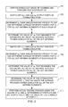
- FIG. 2 illustrates a flow diagram that represents the test method performed by the MIMO test system shown in FIG. 1 in accordance with an illustrative embodiment.
- FIG. 3 illustrates a block diagram of the MIMO test system in accordance with another illustrative embodiment.
- FIG. 4 illustrates a flow diagram of the calibration and actual testing processes shown in FIG. 2 modified to perform a joint optimization algorithm.
- FIG. 5 illustrates a flow diagram of an alternative method to the method represented by the flow diagram shown in FIG. 2 that alters the electromagnetic conditions instead of performing phase tuning and attenuation of the output signals of the fading emulator.
- FIG. 6 illustrates a block diagram of the MIMO test system in accordance with an illustrative embodiment in which electromagnetic conditions are altered by using a switching device to switch the connections between the output ports of a fading emulator and the probe antennas.
- FIG. 7 illustrates a flow diagram of the method performed by the MIMO test system shown in FIG. 6 in accordance with an illustrative embodiment.
- a device includes one device and plural devices.
- memory or “memory device”, as those terms are used herein, are intended to denote a computer-readable storage medium that is capable of storing computer instructions, or computer code, for execution by one or more processors. References herein to “memory” or “memory device” should be interpreted as one or more memories or memory devices.
- the memory may, for example, be multiple memories within the same computer system.
- the memory may also be multiple memories distributed amongst multiple computer systems or computing devices.
- a “processor”, as that term is used herein encompasses an electronic component that is able to execute a computer program or executable computer instructions.
- References herein to a computer comprising “a processor” should be interpreted as a computer having one or more processors or processing cores.
- the processor may for instance be a multi-core processor.
- a processor may also refer to a collection of processors within a single computer system or distributed amongst multiple computer systems.
- the term “computer” should also be interpreted as possibly referring to a collection or network of computers or computing devices, each comprising a processor or processors. Instructions of a computer program can be performed by multiple processors that may be within the same computer or that may be distributed across multiple computers.
- FIG. 1 illustrates a block diagram of the MIMO test system 100 in accordance with an exemplary, or illustrative, embodiment.
- the MIMO test system 100 comprises a base station emulator 101 , a fading emulator 102 , a non-anechoic, electromagnetically-shielded chamber 103 , and a computer 110 , which may be, for example, a PC.
- a mobile DUT 104 is disposed inside of the chamber 103 .
- the computer 110 is electrically coupled by electrical cables 106 and 107 to the base station emulator 101 and to the fading emulator 102 , respectively.
- the computer 110 is in communication with the mobile DUT 104 via either a wired communication link, represented by line 108 , or a wireless communication link, represented by wireless symbol 109 .
- a wired communication link being used between the computer 110 and the mobile DUT 104
- opposite ends of one or more electrical cables are connected to an input/output (I/O) port on the mobile DUT 104 and to an I/O port on the computer 110 .
- the I/O ports of the mobile DUT 104 and of the computer 110 may be, for example, Universal Serial Bus (USB) ports.
- USB Universal Serial Bus
- the base station emulator 101 has M output ports for outputting M time-varying radio frequency (RF) signals, where M is a positive integer that is greater than or equal to 2 and represents the number of antennas that the base station emulator 101 is emulating.
- M is a positive integer that is greater than or equal to 2 and represents the number of antennas that the base station emulator 101 is emulating.
- the fading emulator 102 has M input ports for inputting the first and second time-varying RF signals, x 1 (t) and x 2 (t), respectively.
- the fading emulator 102 has a number of channels over which the first and second time-varying RF signals x 1 (t) and x 2 (t) pass. As the first and second time-varying RF signals x 1 (t) and x 2 (t) pass along these channels, they are operated on in a predetermined manner using a plurality of fading coefficients c 1 (t), c 2 (t), c 3 (t) and c 4 (t) ⁇ 2 , and a plurality of phase-shifted versions of these coefficients, c 1 (t) ⁇ 1 , c 2 (t) ⁇ 2 , c 3 (t) ⁇ 1 and c 4 (t) ⁇ 2 , respectively.
- the manner in which fading emulators perform fading operations is well known and therefore will not be described in detail herein in the interest of brevity.
- the non-anechoic, electromagnetically-shielded chamber 103 has N probe antennas 112 a - 112 d positioned in predetermined spatial relationships relative to the mobile DUT 104 .
- the number of probe antennas 112 a - 112 d equals the number of output ports of the fading emulator 102 and each probe antenna 112 a - 112 d is modulated by one of the faded, time-varying signals Z 1 (t), Z 1 (t) ⁇ 1 , Z 2 (t) and Z 2 (t) ⁇ 2 , respectively.
- the signals that are received by the antenna elements 114 a and 114 b of the mobile DUT 104 are represented by mathematical functions y 1 (t) and y 2 (t).
- the relationships between the output signals x 1 (t) and x 2 (t) of the base station emulator 101 , the fading coefficients c 1 (t)-c 4 (t) of the fading emulator 102 , the output signals Z 1 (t), Z 1 (t) ⁇ 1 , Z 2 (t) and Z 2 (t) ⁇ 2 of the fading emulator 102 , the probe antennas 112 a - 112 d of the chamber 103 , and the antenna elements 114 a and 114 b of the mobile DUT 104 can be mathematically expressed as follows:
- H ⁇ ( t ) [ c 1 ⁇ ( t ) ⁇ ( k 1 + ⁇ 1 ⁇ k 3 ) + c 2 ⁇ ( t ) ⁇ ( k 5 + ⁇ 2 ⁇ k 7 ) c 3 ⁇ ( t ) ⁇ ( k 1 + ⁇ 1 ⁇ k 3 ) + c 4 ⁇ ( t ) ⁇ ( k 5 + ⁇ 2 ⁇ k 7 ) c 1 ⁇ ( t ) ⁇ ( k 2 + ⁇ 1 ⁇ k 4 ) + c 2 ⁇ ( t ) ⁇ ( k 6 + ⁇ 2 ⁇ k 8 ) c 3 ⁇ ( t ) ⁇ ( k 2 + ⁇ 1 ⁇ k 4 ) + c 4 ⁇ ( t ) ⁇ ( k 6 + ⁇ 2 ⁇ k 8 ) c 3 ⁇ ( t ) ⁇ ( k 2 + ⁇ 1 ⁇ k 4
- Equation ⁇ ⁇ 3 H(t) is a time-variant channel matrix containing the radio channel model in the fading emulator 102 , the static radio channel inside the small chamber 103 (including the probe antennas 112 a - 112 d , multipath propagation and the DUT antenna elements 114 a - 114 b ), probe antennas cables (not shown), connectors (not shown), etc.
- the received signal may also be expressed by the following equation:
- z i (t) ⁇ are the output signals of the fading emulator 102
- k i ⁇ are time-invariant channel coefficients of the propagation paths from the probe antennas 112 a - 112 d to the DUT antenna elements 114 a and 114 b inside of the chamber 103 .
- FIG. 2 illustrates a flow diagram that represents the test method performed by the MIMO test system 100 shown in FIG. 1 in accordance with an illustrative embodiment.
- the test method includes a calibration process that is first performed to obtain values to be used for the tunable phase terms and for attenuation coefficients that will be used during the actual testing process. After the calibration process has been performed, the actual testing process is performed using the values for the tunable phase terms and attenuation coefficients obtained during the calibration process.
- the computer 110 has a combination of hardware (e.g., one or more processors) and software and/or firmware for performing algorithms associated with the calibration and actual testing processes.
- the calibration and the actual testing processes will now be described with reference to the illustrative embodiment shown in FIG. 2 .
- the MIMO test system 100 is set up and the mobile DUT 104 is disposed inside of the non-anechoic, electromagnetically-shielded chamber 103 , as indicated by block 201 .
- the test set up process includes configuring the fading emulator 102 to emulate a suitable channel model (e.g., a static constant model) and establishing a call session between the mobile DUT 104 and the base station emulator 101 .
- the Z 2 (t) and Z 2 (t) ⁇ 2 output ports of the fading emulator 102 are switched off, as indicated by block 202 .
- the tunable phase term ⁇ 1 is incremented over an angular range ranging from 0° to 360° and the average received power level at each value of ⁇ 1 is determined over the entire range for each of the DUT antenna elements 114 a and 114 b , as indicated by block 203 .
- the mobile DUT 104 is capable of measuring and reporting its average received power level values for each of the antenna elements 114 a and 114 b at each angle of ⁇ 1 .
- the average received power level value is a Reference Signal Received Power (RSRP) value, which is a measurement that is defined in one or more wireless communications standards, such as the LTE standard.
- the RSRP values are transmitted from the mobile DUT 104 to the computer 110 via the wired or wireless communication links 108 and 109 , respectively.
- the computer 110 executes an algorithm that receives the RSRP values, RSRP 1 and RSRP 2 , for each of the antenna elements 114 a and 114 b , respectively, at each angle of ⁇ 1 .
- the Z 1 (t) and Z 1 (t) ⁇ 1 output ports of the fading emulator 102 are switched off, as indicated by block 207 .
- the tunable phase term ⁇ 2 is incremented over an angular range ranging from 0° to 360° and the RSRP 1 and RSRP 2 values at each angle of ⁇ 2 are determined over the entire range for each of the DUT antenna elements 114 a and 114 b , as indicated by block 208 .
- the value of an attenuation coefficient, x is determined that balances the RSRP 1 and RSRP 2 values for either of the output port pairs, Z 1 (t) and Z 1 (t) ⁇ 1 or Z 2 (t) and Z 2 (t) ⁇ 2 , as indicated by block 211 .
- the phase terms ⁇ 1 and ⁇ 2 determined in blocks 205 and 209 are utilized to force matrix G in Equation 5 to have the format of the diagonal matrix (i.e., entries outside of the main diagonal are all zero values).
- the step represented by block 211 is utilized to balance (i.e., make equal) the diagonal elements of the diagonal matrix G to give it the format of the identity matrix I.
- the value of the attenuation coefficient, x may be calculated by the computer 110 on a linear scale using the ⁇ 1 and ⁇ 2 values determined in the steps represented by blocks 205 and 209 using the following equation:
- Equation ⁇ ⁇ 7 Having determined the ⁇ 1 and ⁇ 2 values and the value of the attenuation coefficient, x, the actual testing process is performed using these values, as indicated by block 213 .
- the fading emulator 102 uses the ⁇ 1 and ⁇ 2 values determined in the steps represented by blocks 205 and 209 to tune the phases of the output signals Z 1 (t) ⁇ 1 and Z 2 (t) ⁇ 2 of the fading emulator 209 and uses the value of the attenuation coefficient x determined at the step represented by block 211 to attenuate the output signals Z 1 (t), Z 1 (t) ⁇ 1 , Z 2 (t) and Z 2 (t) ⁇ 2 of the fading emulator 102 .
- the phase tuning and attenuation processes may be performed by the fading emulator 102 or they may be performed by phase shifting and attenuation devices, respectively, that are external to the fading emulator 102 .
- phase tuning and attenuation processes are performed by the fading emulator 102 .
- the attenuation process is performed as follows: if x ⁇ 1, then the output signals Z 1 (t) and Z 1 (t) ⁇ 1 are attenuated by 1/x; if x>1, then the output signals Z 2 (t) and Z 2 (t) ⁇ 2 are attenuated by x.
- FIG. 3 illustrates a block diagram of the MIMO test system 300 in accordance with another illustrative embodiment.
- the non-anechoic, electromagnetically-shielded chamber 303 has only N/2 probe antenna 112 a and 112 b . Reducing the number of probe antennas that are used in the chamber 303 can decrease the cost of the system 300 . On the other hand, increasing the number of probe antennas that are used in the chamber 303 can increase test accuracy. Therefore, there may be a tradeoff between cost and accuracy.
- the probe antennas 112 a and 112 b are positioned in predetermined spatial relationships relative to the mobile DUT 104 .
- the MIMO test system 300 shown in FIG. 3 includes first and second summers 305 and 306 , respectively.
- the first summer 305 sums the Z 1 (t) and Z 2 (t) output signals together and the second summer 306 sums the Z 1 (t) ⁇ 1 and the Z 2 (t) ⁇ 2 output signals together.
- the output of the first summer 305 is received by the first probe antenna 112 a and the output of the second summer 306 is received by the second probe antenna 112 b . Due to the reduced number of probe antennas 112 a and 112 b used, Equation 4 above is rewritten as follows:
- the calibration and actual testing processes for the MIMO testing system 300 shown in FIG. 3 may be the same as those described above with reference to the flow diagram shown in FIG. 2 .
- RSRP 1 and RSRP 2 are the average received power levels of DUT antenna elements 114 a and 114 b , respectively, determined at the steps represented by blocks 203 and 208 in FIG. 2 , but with all of the outputs of the fading emulator 102 switched on, i.e., the steps represented by blocks 202 and 207 in FIG. 2 are eliminated.
- the optimization expressed by Equation 9 can be performed by the computer 110 executing a suitable optimization algorithm such as, for example, the well-known Simulated Annealing Algorithm.
- FIG. 4 illustrates a flow diagram of the calibration and actual testing processes modified to perform the joint optimization algorithm represented mathematically by Equation 9.
- test method represented by the flow diagram of FIG. 4 is performed by the MIMO test system 100 shown in FIG. 1 .
- the MIMO test system 100 is set up and the mobile DUT 104 is disposed inside of the non-anechoic, electromagnetically-shielded chamber 103 , as indicated by block 401 .
- the test set up process is the same as described above with reference to FIG. 2 .
- the Z 1 (t), Z 1 (t) ⁇ 2 , Z 2 (t) and Z 2 (t) ⁇ 2 output ports of the fading emulator 102 are switched on, as indicated by block 402 .
- the tunable phase term ⁇ 1 is incremented over an angular range ranging from 0° to 360° and the average received power level at each value of ⁇ 1 is determined over the entire range for each of the DUT antenna elements 114 a and 114 b , as indicated by block 403 .
- the tunable phase term ⁇ 2 is incremented over an angular range ranging from 0° to 360° and the RSRP 1 and RSRP 2 values at each angle of ⁇ 2 are determined over the entire range for each of the DUT antenna elements 114 a and 114 b , as indicated by block 405 .
- the computer 110 then executes a joint optimization algorithm, such as the Simulated Annealing Algorithm, that processes the RSRP 1 and RSRP 2 values obtained during the steps represented by blocks 403 and 405 to jointly determine the best values to use for ⁇ 1 , ⁇ 2 and x, as indicated by block 406 .
- the actual testing process is then performed using these values, as indicated by block 407 . Because such joint optimization algorithms are well known, a detailed discussion of the manner in which joint optimization is performed is not provided herein.
- Equation 4 is overdetermined, it is possible that performing the method described above with reference to FIG. 2 may not always yield the best results due to G not being capable of being made close enough to the identity matrix under the current electromagnetic conditions.
- the electromagnetic conditions can be altered in order to alter the channel coefficients, k i .
- One way to alter the electromagnetic conditions is to switch the connections between the output ports of the fading emulator 102 and the probe antennas 112 a - 112 d in order to change the output signals that are applied to the probe antennas 112 a - 112 d .
- Another way to alter the electromagnetic conditions is to use a mechanical three-dimensional (3-D) positioner (not shown) inside of the chamber 103 to rotate the mobile DUT 104 into different 3-D spatial positions relative to the probe antennas 112 a - 112 d .
- Yet another way to alter the electromagnetic conditions is to use one or more movable metallic stirrers (not shown) inside of the chamber 103 in a way that is similar to the way in which they are used in reverberation chambers to change electromagnetic boundary conditions.
- One or more of these techniques of altering the electromagnetic conditions may be used in conjunction with the methods described above with reference to FIGS. 2 and 4 to improve testing accuracy.
- ⁇ 1 and ⁇ 2 values determined during the steps represented by blocks 205 and 209 are not large enough and the value of x determined during the step represented by block 211 is too large, then one or more of the above techniques for altering the electromagnetic conditions may be performed, after which the calibration process represented by blocks 201 - 211 is repeated.
- FIG. 5 illustrates a flow diagram of an alternative method for performing the calibration by altering the electromagnetic conditions until suitable conditions are achieved. The method will be described with reference to the MIMO test system 100 shown in FIG. 1 for exemplary purposes. The steps represented by blocks 501 and 502 are the same as those represented by blocks 201 and 202 , respectively, in FIG. 2 .
- the electromagnetic conditions are altered using one or more of the above techniques, as indicated by block 503 .
- the average received power difference, ⁇ 1 between the RSRP 1 and RSRP 2 values is determined, as indicated by block 505 .
- the Z 1 (t) and Z 1 (t) ⁇ 1 output ports of the fading emulator 102 are switched off, as indicated by block 506 .
- the average received power difference, ⁇ 2 between the RSRP 1 and RSRP 2 is determined, as indicated by block 508 .
- the process represented by blocks 502 through 508 is repeated multiple times to obtain multiple ⁇ 1 and ⁇ 2 values. Each time this process is performed, the electromagnetic conditions and the associated ⁇ 1 and ⁇ 2 values are recorded in memory by the computer 110 . After the process represented by blocks 502 - 508 has been performed a sufficient number of times, the computer 110 selects the electromagnetic conditions that maximized the ⁇ 1 and ⁇ 2 values, as indicated by block 509 . The actual testing process is then performed with the selected electromagnetic conditions duplicated by the MIMO test system 100 , as indicated by block 510 .
- FIG. 6 illustrates a block diagram of the MIMO test system 600 in accordance with an illustrative embodiment in which the aforementioned electromagnetic conditions are altered by using a switching device 603 to switch the connections between the output ports of a fading emulator 602 and probe antennas 612 of a non-anechoic, electromagnetically-shielded chamber 604 .
- a mobile DUT 605 is disposed inside of the chamber 604 .
- FIG. 7 illustrates a flow diagram of the method performed by the MIMO test system 600 in accordance with an illustrative embodiment. The manner in which the MIMO test system 600 performs the method will be described with reference to FIGS. 6 and 7 .
- the MIMO test system 600 includes a computer 610 that may be identical to the computer 110 shown in FIGS. 1 and 3 except that the computer 610 has different or additional software and/or firmware for performing one or more algorithms of the method represented by the flow diagram of FIG. 7 .
- the computer 610 is electrically coupled by electrical cables 606 and 607 to the base station emulator 601 and to the fading emulator 602 , respectively.
- the computer 610 is in communication with the mobile DUT 605 via either a wired communication link, represented by line 608 , or a wireless communication link, represented by wireless symbol 609 .
- the computer 610 is in communication with the switching device 603 via electrical cable 614 .
- it is not necessary to make any connections to antenna connectors (not shown) of the mobile DUT 605 Therefore, there is no need to open up the housing of the mobile DUT 605 and risk damaging or destroying it.
- the fading emulator 602 has N output ports, where N is a positive integer that is greater than or equal to 2. Therefore, N faded, time-varying signals are output from the respective output ports of the fading emulator 602 .
- the chamber 604 has R probe antennas 612 , where R is a positive integer that is greater than N, and typically at least 2N.
- the mobile DUT 605 has a plurality of antenna elements, but for illustrative purposes is assumed to have first and second antenna elements 611 a and 611 b .
- the probe antennas 612 are positioned in predetermined spatial relationships relative to the mobile DUT 605 .
- the step represented by block 701 is similar to the set up process described above with reference to block 201 in FIG. 2 , except that the step represented by block 701 includes measuring the throughput at the DUT antenna elements 611 a and 611 b while adjusting the output power level of the base station emulator 102 to a constant level that is practical and that will allow the measured throughput at the mobile DUT 605 to vary over a range of from zero throughput to a maximum theoretical throughput.
- the method of FIG. 7 relies, in part, on determining the difference between the measured throughput and the maximum theoretical throughput.
- the modulation and coding scheme settings and the transmission mode settings of the base station emulator 101 are known, the theoretical maximum throughput can be determined. Therefore, for purposes of discussion, it is assumed that the theoretical maximum throughput has been determined a priori, and therefore does not have to be determined while performing the method of FIG. 7 .
- the computer 610 causes the switching device 603 to select a set of the output signals of the fading emulator 602 to be provided to a subset of the N probe antennas 612 , as indicated by block 702 .
- Each output signal of the fading emulator 602 has a unique phase value and/or a unique gain value from those of all of the other output signals of the fading emulator 602 .
- Making the selection of block 702 causes a particular subset of the probe antennas 612 to receive respective output signals from the fading emulator 602 that each have particular phase and gain values.
- each different selection of the switching device 603 will result in the mobile DUT 605 being exposed to RF signals having various gain and phase values and propagating along various propagation paths inside of the chamber 604 .
- different selections made by the switching device 603 result in different electromagnetic conditions inside of the chamber 604 .
- the mobile DUT 605 measures the average received power levels of the first and second DUT antenna elements 611 a and 611 b , respectively, and determines the absolute value of the difference between the average received power levels, as indicated by block 703 .
- the mobile DUT 605 measures and reports the average received power levels of the first and second DUT antenna elements 611 a and 611 b , respectively, as RSRP 1 and RSRP 2 values, respectively.
- the absolute value of the difference between these values will be referred to as the ⁇ RSRP value.
- the computer 610 records the ⁇ RSRP value, the set of output signals output from the fading emulator 602 that were selected by the switching device 603 and the subset of probe antennas 612 to which the output signals were provided.
- the manner in which the average received power levels of the DUT antenna elements are measured and the difference between them obtained and reported to the computer 610 has been described above with reference to FIG. 2 .
- the throughput of the mobile DUT 605 is also determined, as indicated by block 704 .
- the selection made at block 702 that results in the highest throughput and the smallest ⁇ RSRP value is the one that should be used during the actual testing process. For this reason, determinations are made at block 705 as to how close the ⁇ RSRP value is to the zero and how close the measured throughput is to the maximum theoretical throughput. If these values are sufficiently close, then the selection made by the switching device 603 at block 702 is suitable for use during the actual testing process.
- the selection made by the switching device 603 at block 702 is suitable for use during the actual testing process. Therefore, if a decision is made at block 706 that these values have matches or near matches, the process proceeds to block 708 .
- actual testing is performed using the selected set of output signals and subset of probe antennas 612 made at block 702 .
- the computer 110 determines which of all possible combinations of output signals from the fading emulator 602 and subsets of probe antennas 612 resulted in the closest matches at block 705 and then causes that selection to be used for the actual testing process.
- decision block 706 could be eliminated, in which case block 708 would use the selection that resulted in the closest match determinations at block 705 .
- a mechanical 3-D positioner (not shown) and/or a movable metallic stirrer (not shown) may be used in combination with, or in lieu of, the switching device 603 , in which case the algorithm represented by FIG. 7 would be altered accordingly.
- block 702 will be replaced with a block directed to positioning the 3-D positioner and/or the stirrer. In that case, all of the other blocks shown in FIG. 7 may remain unchanged. Then, whichever positioning selection results in the matches or near matches at block 706 will be used in the actual testing process at block 708 .
- Persons of skill in the art will understand, in view of the description provided herein, how these and many other modifications may be made to the algorithms and that such modifications are within the scope of the invention.
- the non-anechoic, electromagnetically-shielded chambers 103 , 303 , 604 are relatively small, e.g., 30 centimeters (cm) in height ⁇ 43 cm in width ⁇ 60 cm in length.
- An example of a suitable, commercially-available chamber is the STE3600 enclosure offered by Ramsey Electronics of Victor, N.Y.
- the chambers 103 , 303 , 604 are not limited dimensionally, except that they must be large enough to contain the probe antennas and the mobile DUT.
- the chambers 103 , 303 , 604 also are not limited with respect to their electromagnetic characteristics except that they should provide electromagnetic shielding so that electromagnetic radiation does not escape from the chambers 103 , 303 , 604 .
- the chambers 103 , 303 , 604 will typically be made to exhibit some amount of electromagnetic radiation absorption on their interior surfaces and some amount of electromagnetic reverberation on their interior surfaces.
- Persons skilled in the art will understand, in view of the disclosure provided herein, how to choose a suitable non-anechoic, electromagnetically-shielded chamber, or enclosure, for use in the test system in view of the discussion provided herein.
- the computers 110 and 610 have one or more processors (not shown) configured to execute computer instructions, or code, in the form of software and/or firmware to perform one or more of the algorithms described above with reference to FIGS. 2, 4, 5 and 7 . These instructions are stored in one or more memory devices that are internal to or external to the computers 110 , 610 . Such memory devices constitute non-transient computer-readable mediums. A variety of non-transient computer-readable mediums are suitable for use with the invention, including, for example, solid state storage devices, magnetic storage devices and optical storage devices.
Landscapes
- Engineering & Computer Science (AREA)
- Computer Networks & Wireless Communication (AREA)
- Signal Processing (AREA)
- Physics & Mathematics (AREA)
- Electromagnetism (AREA)
- Monitoring And Testing Of Transmission In General (AREA)
Abstract
Description
where H(t) is expressed by as follows:
H(t) is a time-variant channel matrix containing the radio channel model in the fading
where zi(t)ε
G=I. Equation 5:
This condition may be accomplished by tuning the tunable phase terms, φi, in a calibration procedure to obtain values for the tunable phase terms that satisfy the condition of Equation 5. The manner in which this is accomplished for the illustrative embodiment shown in
Having determined the φ1 and φ2 values and the value of the attenuation coefficient, x, the actual testing process is performed using these values, as indicated by
The calibration and actual testing processes for the
where θ is a parameter vector defined as θ={φ1, φ2, a1, a2, a3, a4}, wiε
Claims (40)
Priority Applications (1)
| Application Number | Priority Date | Filing Date | Title |
|---|---|---|---|
| US15/054,847 US9742508B1 (en) | 2016-02-26 | 2016-02-26 | Systems and methods for calibrating multiple input, multiple output (MIMO) test systems and for using the calibrated MIMO test systems to test mobile devices |
Applications Claiming Priority (1)
| Application Number | Priority Date | Filing Date | Title |
|---|---|---|---|
| US15/054,847 US9742508B1 (en) | 2016-02-26 | 2016-02-26 | Systems and methods for calibrating multiple input, multiple output (MIMO) test systems and for using the calibrated MIMO test systems to test mobile devices |
Publications (1)
| Publication Number | Publication Date |
|---|---|
| US9742508B1 true US9742508B1 (en) | 2017-08-22 |
Family
ID=59581658
Family Applications (1)
| Application Number | Title | Priority Date | Filing Date |
|---|---|---|---|
| US15/054,847 Active US9742508B1 (en) | 2016-02-26 | 2016-02-26 | Systems and methods for calibrating multiple input, multiple output (MIMO) test systems and for using the calibrated MIMO test systems to test mobile devices |
Country Status (1)
| Country | Link |
|---|---|
| US (1) | US9742508B1 (en) |
Cited By (20)
| Publication number | Priority date | Publication date | Assignee | Title |
|---|---|---|---|---|
| US10033473B1 (en) * | 2017-01-23 | 2018-07-24 | Keysight Technologies, Inc. | Systems and methods for performing multiple input, multiple output (MIMO) over-the-air testing |
| US10103823B1 (en) | 2017-09-30 | 2018-10-16 | Keysight Technologies, Inc. | Radio channel emulator having a dynamically-variable channel model for use in testing base stations and user equipment (UE) that perform analog beam forming |
| US10110326B1 (en) * | 2017-09-30 | 2018-10-23 | Keysight Technologies, Inc. | Multi-probe anechoic chamber (MPAC) over-the-air (OTA) test system having a radio channel (RC) emulator that has a dynamically-variable channel model, and methods |
| CN108964800A (en) * | 2018-07-27 | 2018-12-07 | 北京小米移动软件有限公司 | The antenna performance detection method and system of mobile terminal |
| US20190158198A1 (en) * | 2017-11-21 | 2019-05-23 | General Test Systems Inc. | Method and device for measuring radiation pattern of antenna array, and computer readable storage medium |
| US10326539B2 (en) * | 2017-04-12 | 2019-06-18 | Rohde & Schwarz Gmbh & Co. Kg | Test system and test method |
| US10461869B1 (en) * | 2019-02-14 | 2019-10-29 | Rohde & Schwarz Gmbh & Co. Kg | Method for downlink power tests, test system as well as test setup |
| US10505646B2 (en) | 2017-12-15 | 2019-12-10 | Keysight Technologies, Inc. | Systems and methods for testing a wireless device having a beamforming circuit |
| US10601695B2 (en) | 2016-09-01 | 2020-03-24 | Keysight Technologies, Inc. | Systems and methods for radio channel emulation of a multiple input multiple output (MIMO) wireless link |
| CN111385036A (en) * | 2018-12-28 | 2020-07-07 | 深圳市通用测试系统有限公司 | Radio frequency performance testing method, device and tester of wireless equipment |
| US10735110B2 (en) | 2018-12-07 | 2020-08-04 | Keysight Technologies, Inc. | Methods, systems, and computer readable media for testing and modeling beamforming capabilities of a device under test |
| EP3699612A1 (en) * | 2019-02-19 | 2020-08-26 | Rohde & Schwarz GmbH & Co. KG | Method for performing a radiated two-stage method measurement as well as measurement setup |
| CN111865371A (en) * | 2019-04-29 | 2020-10-30 | 深圳市通用测试系统有限公司 | Multi-antenna wireless equipment MIMO test set |
| CN112649697A (en) * | 2020-12-01 | 2021-04-13 | 珠海博杰电子股份有限公司 | Test module and signal test method |
| US11088744B1 (en) | 2020-02-07 | 2021-08-10 | Keysight Technologies, Inc. | Methods, systems, and computer readable media for 5G digital beamforming testing |
| US20210314075A1 (en) * | 2018-11-26 | 2021-10-07 | General Test Systems Inc. | Method and system for testing wireless performance of wireless terminal |
| EP3993287A1 (en) * | 2020-10-30 | 2022-05-04 | Rohde & Schwarz GmbH & Co. KG | Method for determining a pre-equalization matrix and test setup |
| US11337090B2 (en) | 2019-01-28 | 2022-05-17 | Volvo Car Corporation | Telematics verification system |
| CN116008677A (en) * | 2022-12-28 | 2023-04-25 | 北京天地一格科技有限公司 | A field calibration device and a field calibration method for a phased array antenna |
| US20250105932A1 (en) * | 2023-09-27 | 2025-03-27 | T-Mobile Usa, Inc. | Radio frequency enclosure attenuation calibration |
Citations (7)
| Publication number | Priority date | Publication date | Assignee | Title |
|---|---|---|---|---|
| US20110299570A1 (en) * | 2009-02-13 | 2011-12-08 | Spirent Communications, Inc. | Emulation and controlled testing of mimo ota channels |
| US20120207030A1 (en) * | 2011-02-10 | 2012-08-16 | Anh Luong | Methods for testing wireless local area network transceivers in wireless electronic devices |
| US20130303089A1 (en) * | 2012-05-11 | 2013-11-14 | Apple Inc. | Uplink and/or Downlink Testing of Wireless Devices in a Reverberation Chamber |
| US20140087668A1 (en) * | 2012-09-27 | 2014-03-27 | Apple Inc | Methods and Apparatus for Performing Coexistence Testing for Multi-Antenna Electronic Devices |
| US8811461B1 (en) | 2013-03-15 | 2014-08-19 | Litepoint Corporation | System and method for testing radio frequency wireless signal transceivers using wireless test signals |
| US20150025818A1 (en) * | 2013-07-16 | 2015-01-22 | Azimuth Systems, Inc. | Synchronized testing of multiple wireless devices |
| US20150280844A1 (en) | 2012-12-03 | 2015-10-01 | General Test Systems Inc. | Method and device for testing performance of wireless terminal |
-
2016
- 2016-02-26 US US15/054,847 patent/US9742508B1/en active Active
Patent Citations (7)
| Publication number | Priority date | Publication date | Assignee | Title |
|---|---|---|---|---|
| US20110299570A1 (en) * | 2009-02-13 | 2011-12-08 | Spirent Communications, Inc. | Emulation and controlled testing of mimo ota channels |
| US20120207030A1 (en) * | 2011-02-10 | 2012-08-16 | Anh Luong | Methods for testing wireless local area network transceivers in wireless electronic devices |
| US20130303089A1 (en) * | 2012-05-11 | 2013-11-14 | Apple Inc. | Uplink and/or Downlink Testing of Wireless Devices in a Reverberation Chamber |
| US20140087668A1 (en) * | 2012-09-27 | 2014-03-27 | Apple Inc | Methods and Apparatus for Performing Coexistence Testing for Multi-Antenna Electronic Devices |
| US20150280844A1 (en) | 2012-12-03 | 2015-10-01 | General Test Systems Inc. | Method and device for testing performance of wireless terminal |
| US8811461B1 (en) | 2013-03-15 | 2014-08-19 | Litepoint Corporation | System and method for testing radio frequency wireless signal transceivers using wireless test signals |
| US20150025818A1 (en) * | 2013-07-16 | 2015-01-22 | Azimuth Systems, Inc. | Synchronized testing of multiple wireless devices |
Non-Patent Citations (2)
| Title |
|---|
| Rumney, et al., "Advances in Antenna Pattern-Based MIMO OTA Test Methods", 2015 9th European Conference on Antennas and Propagation (EuCAP), Lisbon, Apr. 13-17, 2015. |
| Yu, et al., "Radiated Two-Stage Method for LTE MIMO User Equipment Performance Evaluation", IEEE Transactions on Electromagnetic Compatability vol. 56, No. 6, p. 1691-1696, Dec. 2014. |
Cited By (28)
| Publication number | Priority date | Publication date | Assignee | Title |
|---|---|---|---|---|
| US10601695B2 (en) | 2016-09-01 | 2020-03-24 | Keysight Technologies, Inc. | Systems and methods for radio channel emulation of a multiple input multiple output (MIMO) wireless link |
| US10033473B1 (en) * | 2017-01-23 | 2018-07-24 | Keysight Technologies, Inc. | Systems and methods for performing multiple input, multiple output (MIMO) over-the-air testing |
| US10326539B2 (en) * | 2017-04-12 | 2019-06-18 | Rohde & Schwarz Gmbh & Co. Kg | Test system and test method |
| US10103823B1 (en) | 2017-09-30 | 2018-10-16 | Keysight Technologies, Inc. | Radio channel emulator having a dynamically-variable channel model for use in testing base stations and user equipment (UE) that perform analog beam forming |
| US10110326B1 (en) * | 2017-09-30 | 2018-10-23 | Keysight Technologies, Inc. | Multi-probe anechoic chamber (MPAC) over-the-air (OTA) test system having a radio channel (RC) emulator that has a dynamically-variable channel model, and methods |
| US11422176B2 (en) * | 2017-11-21 | 2022-08-23 | General Test Systems Inc. | Method and device for measuring radiation pattern of antenna array, and computer readable storage medium |
| US20190158198A1 (en) * | 2017-11-21 | 2019-05-23 | General Test Systems Inc. | Method and device for measuring radiation pattern of antenna array, and computer readable storage medium |
| US11108474B2 (en) | 2017-12-15 | 2021-08-31 | Keysight Technologies, Inc. | Systems and methods for testing a wireless device having a beamforming circuit |
| US10505646B2 (en) | 2017-12-15 | 2019-12-10 | Keysight Technologies, Inc. | Systems and methods for testing a wireless device having a beamforming circuit |
| CN108964800B (en) * | 2018-07-27 | 2021-07-27 | 北京小米移动软件有限公司 | Antenna performance detection method and system for mobile terminal |
| CN108964800A (en) * | 2018-07-27 | 2018-12-07 | 北京小米移动软件有限公司 | The antenna performance detection method and system of mobile terminal |
| US20210314075A1 (en) * | 2018-11-26 | 2021-10-07 | General Test Systems Inc. | Method and system for testing wireless performance of wireless terminal |
| US11962357B2 (en) * | 2018-11-26 | 2024-04-16 | General Test Systems Inc. | Method and system for testing wireless performance of wireless terminal |
| US10735110B2 (en) | 2018-12-07 | 2020-08-04 | Keysight Technologies, Inc. | Methods, systems, and computer readable media for testing and modeling beamforming capabilities of a device under test |
| CN111385036A (en) * | 2018-12-28 | 2020-07-07 | 深圳市通用测试系统有限公司 | Radio frequency performance testing method, device and tester of wireless equipment |
| US11337090B2 (en) | 2019-01-28 | 2022-05-17 | Volvo Car Corporation | Telematics verification system |
| US10461869B1 (en) * | 2019-02-14 | 2019-10-29 | Rohde & Schwarz Gmbh & Co. Kg | Method for downlink power tests, test system as well as test setup |
| US11165513B2 (en) | 2019-02-19 | 2021-11-02 | Rohde & Schwarz Gmbh & Co. Kg | Method for performing a radiated two-stage method measurement as well as measurement setup |
| EP3699612A1 (en) * | 2019-02-19 | 2020-08-26 | Rohde & Schwarz GmbH & Co. KG | Method for performing a radiated two-stage method measurement as well as measurement setup |
| CN111865371B (en) * | 2019-04-29 | 2021-11-09 | 深圳市通用测试系统有限公司 | MIMO testing device for multi-antenna wireless equipment |
| CN111865371A (en) * | 2019-04-29 | 2020-10-30 | 深圳市通用测试系统有限公司 | Multi-antenna wireless equipment MIMO test set |
| US11088744B1 (en) | 2020-02-07 | 2021-08-10 | Keysight Technologies, Inc. | Methods, systems, and computer readable media for 5G digital beamforming testing |
| EP3993287A1 (en) * | 2020-10-30 | 2022-05-04 | Rohde & Schwarz GmbH & Co. KG | Method for determining a pre-equalization matrix and test setup |
| CN114448480A (en) * | 2020-10-30 | 2022-05-06 | 罗德施瓦兹两合股份有限公司 | Method and test device for determining a pre-equalization matrix |
| US11996898B2 (en) | 2020-10-30 | 2024-05-28 | Rohde & Schwarz Gmbh & Co. Kg | Method for determining a pre-equalization matrix and test setup |
| CN112649697A (en) * | 2020-12-01 | 2021-04-13 | 珠海博杰电子股份有限公司 | Test module and signal test method |
| CN116008677A (en) * | 2022-12-28 | 2023-04-25 | 北京天地一格科技有限公司 | A field calibration device and a field calibration method for a phased array antenna |
| US20250105932A1 (en) * | 2023-09-27 | 2025-03-27 | T-Mobile Usa, Inc. | Radio frequency enclosure attenuation calibration |
Similar Documents
| Publication | Publication Date | Title |
|---|---|---|
| US9742508B1 (en) | Systems and methods for calibrating multiple input, multiple output (MIMO) test systems and for using the calibrated MIMO test systems to test mobile devices | |
| US10574369B2 (en) | Systems and methods for calibrating out the radiation channel matrix in a multiple input, multiple output (MIMO) over-the-air (OTA) radiated test system | |
| US10601695B2 (en) | Systems and methods for radio channel emulation of a multiple input multiple output (MIMO) wireless link | |
| US10033473B1 (en) | Systems and methods for performing multiple input, multiple output (MIMO) over-the-air testing | |
| US11108474B2 (en) | Systems and methods for testing a wireless device having a beamforming circuit | |
| JP5607237B2 (en) | Test system using wireless communication | |
| US10935584B2 (en) | System and method for determining beam dynamics and multi-user performance of base station | |
| US10684318B1 (en) | System and method for testing analog beamforming device | |
| EP3361654B1 (en) | Wireless performance testing method for mimo wireless terminal | |
| US11962357B2 (en) | Method and system for testing wireless performance of wireless terminal | |
| Kildal et al. | OTA testing in multipath of antennas and wireless devices with MIMO and OFDM | |
| JP6464151B2 (en) | System and method for testing radio frequency radio signal transceivers using radio test signals | |
| Chen et al. | Comparison of ergodic capacities from wideband MIMO antenna measurements in reverberation chamber and anechoic chamber | |
| Llorente et al. | MIMO OTA testing in small multiprobe anechoic chamber setups | |
| US20240171291A1 (en) | Method and apparatus for multiple-input multiple-output (mimo) testing user equipment (ue) | |
| Xu et al. | A new antenna diversity gain measurement method using a reverberation chamber | |
| CN116368839A (en) | Systems and methods for determining corrected total radiated power (TRP) or corrected total isotropic sensitivity (TIS) of an offset antenna under test | |
| Miah et al. | On the field emulation techniques in over-the-air testing: Experimental throughput comparison | |
| EP4589864A1 (en) | Calibration of a phase shift matrix for cable-connected testing of a massive multiple-input multiple-output base station | |
| Fan et al. | Channel spatial profile validation for FR2 new radio over-the-air testing | |
| WO2024234373A1 (en) | A test method for ecc calculation based on ota 2 tx trp measurement | |
| Laitinen et al. | On a MIMO-OTA testing based on multi-probe technology | |
| Fan et al. | MIMO device performance testing with the wireless cable method | |
| Kildal et al. | MIMO LTE OTA measurements in reverberation chamber: rich isotropic reference environment makes agreement with theoretical system model | |
| Khatun et al. | Research Article Dependence of Error Level on the Number of Probes in Over-the-Air Multiprobe Test Systems |
Legal Events
| Date | Code | Title | Description |
|---|---|---|---|
| AS | Assignment |
Owner name: KEYSIGHT TECHNOLOGIES, INC., CALIFORNIA Free format text: ASSIGNMENT OF ASSIGNORS INTEREST;ASSIGNORS:KYOSTI, PEKKA;HENTILA, LASSI;KYROLAINEN, JUKKA;AND OTHERS;SIGNING DATES FROM 20160414 TO 20160418;REEL/FRAME:038304/0697 |
|
| STCF | Information on status: patent grant |
Free format text: PATENTED CASE |
|
| MAFP | Maintenance fee payment |
Free format text: PAYMENT OF MAINTENANCE FEE, 4TH YEAR, LARGE ENTITY (ORIGINAL EVENT CODE: M1551); ENTITY STATUS OF PATENT OWNER: LARGE ENTITY Year of fee payment: 4 |
|
| MAFP | Maintenance fee payment |
Free format text: PAYMENT OF MAINTENANCE FEE, 8TH YEAR, LARGE ENTITY (ORIGINAL EVENT CODE: M1552); ENTITY STATUS OF PATENT OWNER: LARGE ENTITY Year of fee payment: 8 |