US9737408B2 - Tibial impaction guide surgical instrument and method of using same - Google Patents
Tibial impaction guide surgical instrument and method of using same Download PDFInfo
- Publication number
- US9737408B2 US9737408B2 US13/833,208 US201313833208A US9737408B2 US 9737408 B2 US9737408 B2 US 9737408B2 US 201313833208 A US201313833208 A US 201313833208A US 9737408 B2 US9737408 B2 US 9737408B2
- Authority
- US
- United States
- Prior art keywords
- component
- cup
- wall
- surgical instrument
- orthopaedic surgical
- Prior art date
- Legal status (The legal status is an assumption and is not a legal conclusion. Google has not performed a legal analysis and makes no representation as to the accuracy of the status listed.)
- Active, expires
Links
- 238000000034 method Methods 0.000 title description 14
- 230000007423 decrease Effects 0.000 claims description 4
- 210000002303 tibia Anatomy 0.000 description 36
- 210000003127 knee Anatomy 0.000 description 20
- 210000000988 bone and bone Anatomy 0.000 description 10
- 238000001356 surgical procedure Methods 0.000 description 10
- 210000000689 upper leg Anatomy 0.000 description 7
- 210000003484 anatomy Anatomy 0.000 description 6
- 238000005192 partition Methods 0.000 description 6
- 239000000463 material Substances 0.000 description 5
- 230000008901 benefit Effects 0.000 description 3
- 238000002513 implantation Methods 0.000 description 3
- 238000012986 modification Methods 0.000 description 3
- 230000004048 modification Effects 0.000 description 3
- 229920000642 polymer Polymers 0.000 description 3
- 229910000684 Cobalt-chrome Inorganic materials 0.000 description 2
- 239000000956 alloy Substances 0.000 description 2
- 239000010952 cobalt-chrome Substances 0.000 description 2
- 239000007943 implant Substances 0.000 description 2
- 210000000629 knee joint Anatomy 0.000 description 2
- 238000013150 knee replacement Methods 0.000 description 2
- 229910052751 metal Inorganic materials 0.000 description 2
- 239000002184 metal Substances 0.000 description 2
- -1 polyethylene Polymers 0.000 description 2
- 229910001220 stainless steel Inorganic materials 0.000 description 2
- 239000010935 stainless steel Substances 0.000 description 2
- 229910000851 Alloy steel Inorganic materials 0.000 description 1
- 229910000531 Co alloy Inorganic materials 0.000 description 1
- 239000004698 Polyethylene Substances 0.000 description 1
- 229910001069 Ti alloy Inorganic materials 0.000 description 1
- 229910000883 Ti6Al4V Inorganic materials 0.000 description 1
- RTAQQCXQSZGOHL-UHFFFAOYSA-N Titanium Chemical compound [Ti] RTAQQCXQSZGOHL-UHFFFAOYSA-N 0.000 description 1
- 229920010741 Ultra High Molecular Weight Polyethylene (UHMWPE) Polymers 0.000 description 1
- WAIPAZQMEIHHTJ-UHFFFAOYSA-N [Cr].[Co] Chemical compound [Cr].[Co] WAIPAZQMEIHHTJ-UHFFFAOYSA-N 0.000 description 1
- 229910045601 alloy Inorganic materials 0.000 description 1
- 238000011882 arthroplasty Methods 0.000 description 1
- 229910017052 cobalt Inorganic materials 0.000 description 1
- 239000010941 cobalt Substances 0.000 description 1
- GUTLYIVDDKVIGB-UHFFFAOYSA-N cobalt atom Chemical compound [Co] GUTLYIVDDKVIGB-UHFFFAOYSA-N 0.000 description 1
- 238000005530 etching Methods 0.000 description 1
- 229910052588 hydroxylapatite Inorganic materials 0.000 description 1
- 238000009434 installation Methods 0.000 description 1
- 239000007769 metal material Substances 0.000 description 1
- 150000002739 metals Chemical class 0.000 description 1
- XYJRXVWERLGGKC-UHFFFAOYSA-D pentacalcium;hydroxide;triphosphate Chemical compound [OH-].[Ca+2].[Ca+2].[Ca+2].[Ca+2].[Ca+2].[O-]P([O-])([O-])=O.[O-]P([O-])([O-])=O.[O-]P([O-])([O-])=O XYJRXVWERLGGKC-UHFFFAOYSA-D 0.000 description 1
- 229920000573 polyethylene Polymers 0.000 description 1
- 238000002360 preparation method Methods 0.000 description 1
- 230000000087 stabilizing effect Effects 0.000 description 1
- 238000004381 surface treatment Methods 0.000 description 1
- 229910052719 titanium Inorganic materials 0.000 description 1
- 239000010936 titanium Substances 0.000 description 1
- 238000011883 total knee arthroplasty Methods 0.000 description 1
- 230000000007 visual effect Effects 0.000 description 1
Images


Classifications
-
- A—HUMAN NECESSITIES
- A61—MEDICAL OR VETERINARY SCIENCE; HYGIENE
- A61F—FILTERS IMPLANTABLE INTO BLOOD VESSELS; PROSTHESES; DEVICES PROVIDING PATENCY TO, OR PREVENTING COLLAPSING OF, TUBULAR STRUCTURES OF THE BODY, e.g. STENTS; ORTHOPAEDIC, NURSING OR CONTRACEPTIVE DEVICES; FOMENTATION; TREATMENT OR PROTECTION OF EYES OR EARS; BANDAGES, DRESSINGS OR ABSORBENT PADS; FIRST-AID KITS
- A61F2/00—Filters implantable into blood vessels; Prostheses, i.e. artificial substitutes or replacements for parts of the body; Appliances for connecting them with the body; Devices providing patency to, or preventing collapsing of, tubular structures of the body, e.g. stents
- A61F2/02—Prostheses implantable into the body
- A61F2/30—Joints
- A61F2/38—Joints for elbows or knees
- A61F2/389—Tibial components
-
- A—HUMAN NECESSITIES
- A61—MEDICAL OR VETERINARY SCIENCE; HYGIENE
- A61F—FILTERS IMPLANTABLE INTO BLOOD VESSELS; PROSTHESES; DEVICES PROVIDING PATENCY TO, OR PREVENTING COLLAPSING OF, TUBULAR STRUCTURES OF THE BODY, e.g. STENTS; ORTHOPAEDIC, NURSING OR CONTRACEPTIVE DEVICES; FOMENTATION; TREATMENT OR PROTECTION OF EYES OR EARS; BANDAGES, DRESSINGS OR ABSORBENT PADS; FIRST-AID KITS
- A61F2/00—Filters implantable into blood vessels; Prostheses, i.e. artificial substitutes or replacements for parts of the body; Appliances for connecting them with the body; Devices providing patency to, or preventing collapsing of, tubular structures of the body, e.g. stents
- A61F2/02—Prostheses implantable into the body
- A61F2/30—Joints
- A61F2/38—Joints for elbows or knees
- A61F2/3859—Femoral components
-
- A—HUMAN NECESSITIES
- A61—MEDICAL OR VETERINARY SCIENCE; HYGIENE
- A61F—FILTERS IMPLANTABLE INTO BLOOD VESSELS; PROSTHESES; DEVICES PROVIDING PATENCY TO, OR PREVENTING COLLAPSING OF, TUBULAR STRUCTURES OF THE BODY, e.g. STENTS; ORTHOPAEDIC, NURSING OR CONTRACEPTIVE DEVICES; FOMENTATION; TREATMENT OR PROTECTION OF EYES OR EARS; BANDAGES, DRESSINGS OR ABSORBENT PADS; FIRST-AID KITS
- A61F2/00—Filters implantable into blood vessels; Prostheses, i.e. artificial substitutes or replacements for parts of the body; Appliances for connecting them with the body; Devices providing patency to, or preventing collapsing of, tubular structures of the body, e.g. stents
- A61F2/02—Prostheses implantable into the body
- A61F2/30—Joints
- A61F2/46—Special tools for implanting artificial joints
- A61F2/4603—Special tools for implanting artificial joints for insertion or extraction of endoprosthetic joints or of accessories thereof
- A61F2/461—Special tools for implanting artificial joints for insertion or extraction of endoprosthetic joints or of accessories thereof of knees
-
- A—HUMAN NECESSITIES
- A61—MEDICAL OR VETERINARY SCIENCE; HYGIENE
- A61F—FILTERS IMPLANTABLE INTO BLOOD VESSELS; PROSTHESES; DEVICES PROVIDING PATENCY TO, OR PREVENTING COLLAPSING OF, TUBULAR STRUCTURES OF THE BODY, e.g. STENTS; ORTHOPAEDIC, NURSING OR CONTRACEPTIVE DEVICES; FOMENTATION; TREATMENT OR PROTECTION OF EYES OR EARS; BANDAGES, DRESSINGS OR ABSORBENT PADS; FIRST-AID KITS
- A61F2/00—Filters implantable into blood vessels; Prostheses, i.e. artificial substitutes or replacements for parts of the body; Appliances for connecting them with the body; Devices providing patency to, or preventing collapsing of, tubular structures of the body, e.g. stents
- A61F2/02—Prostheses implantable into the body
- A61F2/30—Joints
- A61F2002/30001—Additional features of subject-matter classified in A61F2/28, A61F2/30 and subgroups thereof
- A61F2002/30316—The prosthesis having different structural features at different locations within the same prosthesis; Connections between prosthetic parts; Special structural features of bone or joint prostheses not otherwise provided for
- A61F2002/30329—Connections or couplings between prosthetic parts, e.g. between modular parts; Connecting elements
- A61F2002/30331—Connections or couplings between prosthetic parts, e.g. between modular parts; Connecting elements made by longitudinally pushing a protrusion into a complementarily-shaped recess, e.g. held by friction fit
- A61F2002/30332—Conically- or frustoconically-shaped protrusion and recess
-
- A—HUMAN NECESSITIES
- A61—MEDICAL OR VETERINARY SCIENCE; HYGIENE
- A61F—FILTERS IMPLANTABLE INTO BLOOD VESSELS; PROSTHESES; DEVICES PROVIDING PATENCY TO, OR PREVENTING COLLAPSING OF, TUBULAR STRUCTURES OF THE BODY, e.g. STENTS; ORTHOPAEDIC, NURSING OR CONTRACEPTIVE DEVICES; FOMENTATION; TREATMENT OR PROTECTION OF EYES OR EARS; BANDAGES, DRESSINGS OR ABSORBENT PADS; FIRST-AID KITS
- A61F2/00—Filters implantable into blood vessels; Prostheses, i.e. artificial substitutes or replacements for parts of the body; Appliances for connecting them with the body; Devices providing patency to, or preventing collapsing of, tubular structures of the body, e.g. stents
- A61F2/02—Prostheses implantable into the body
- A61F2/30—Joints
- A61F2002/30001—Additional features of subject-matter classified in A61F2/28, A61F2/30 and subgroups thereof
- A61F2002/30316—The prosthesis having different structural features at different locations within the same prosthesis; Connections between prosthetic parts; Special structural features of bone or joint prostheses not otherwise provided for
- A61F2002/30535—Special structural features of bone or joint prostheses not otherwise provided for
- A61F2002/30594—Special structural features of bone or joint prostheses not otherwise provided for slotted, e.g. radial or meridian slot ending in a polar aperture, non-polar slots, horizontal or arcuate slots
-
- A—HUMAN NECESSITIES
- A61—MEDICAL OR VETERINARY SCIENCE; HYGIENE
- A61F—FILTERS IMPLANTABLE INTO BLOOD VESSELS; PROSTHESES; DEVICES PROVIDING PATENCY TO, OR PREVENTING COLLAPSING OF, TUBULAR STRUCTURES OF THE BODY, e.g. STENTS; ORTHOPAEDIC, NURSING OR CONTRACEPTIVE DEVICES; FOMENTATION; TREATMENT OR PROTECTION OF EYES OR EARS; BANDAGES, DRESSINGS OR ABSORBENT PADS; FIRST-AID KITS
- A61F2/00—Filters implantable into blood vessels; Prostheses, i.e. artificial substitutes or replacements for parts of the body; Appliances for connecting them with the body; Devices providing patency to, or preventing collapsing of, tubular structures of the body, e.g. stents
- A61F2/02—Prostheses implantable into the body
- A61F2/30—Joints
- A61F2002/30001—Additional features of subject-matter classified in A61F2/28, A61F2/30 and subgroups thereof
- A61F2002/30316—The prosthesis having different structural features at different locations within the same prosthesis; Connections between prosthetic parts; Special structural features of bone or joint prostheses not otherwise provided for
- A61F2002/30535—Special structural features of bone or joint prostheses not otherwise provided for
- A61F2002/30604—Special structural features of bone or joint prostheses not otherwise provided for modular
- A61F2002/30616—Sets comprising a plurality of prosthetic parts of different sizes or orientations
-
- A—HUMAN NECESSITIES
- A61—MEDICAL OR VETERINARY SCIENCE; HYGIENE
- A61F—FILTERS IMPLANTABLE INTO BLOOD VESSELS; PROSTHESES; DEVICES PROVIDING PATENCY TO, OR PREVENTING COLLAPSING OF, TUBULAR STRUCTURES OF THE BODY, e.g. STENTS; ORTHOPAEDIC, NURSING OR CONTRACEPTIVE DEVICES; FOMENTATION; TREATMENT OR PROTECTION OF EYES OR EARS; BANDAGES, DRESSINGS OR ABSORBENT PADS; FIRST-AID KITS
- A61F2/00—Filters implantable into blood vessels; Prostheses, i.e. artificial substitutes or replacements for parts of the body; Appliances for connecting them with the body; Devices providing patency to, or preventing collapsing of, tubular structures of the body, e.g. stents
- A61F2/02—Prostheses implantable into the body
- A61F2/30—Joints
- A61F2002/30001—Additional features of subject-matter classified in A61F2/28, A61F2/30 and subgroups thereof
- A61F2002/30667—Features concerning an interaction with the environment or a particular use of the prosthesis
- A61F2002/3069—Revision endoprostheses
-
- A—HUMAN NECESSITIES
- A61—MEDICAL OR VETERINARY SCIENCE; HYGIENE
- A61F—FILTERS IMPLANTABLE INTO BLOOD VESSELS; PROSTHESES; DEVICES PROVIDING PATENCY TO, OR PREVENTING COLLAPSING OF, TUBULAR STRUCTURES OF THE BODY, e.g. STENTS; ORTHOPAEDIC, NURSING OR CONTRACEPTIVE DEVICES; FOMENTATION; TREATMENT OR PROTECTION OF EYES OR EARS; BANDAGES, DRESSINGS OR ABSORBENT PADS; FIRST-AID KITS
- A61F2/00—Filters implantable into blood vessels; Prostheses, i.e. artificial substitutes or replacements for parts of the body; Appliances for connecting them with the body; Devices providing patency to, or preventing collapsing of, tubular structures of the body, e.g. stents
- A61F2/02—Prostheses implantable into the body
- A61F2/30—Joints
- A61F2/30721—Accessories
- A61F2/30734—Modular inserts, sleeves or augments, e.g. placed on proximal part of stem for fixation purposes or wedges for bridging a bone defect
- A61F2002/30736—Augments or augmentation pieces, e.g. wedges or blocks for bridging a bone defect
-
- A—HUMAN NECESSITIES
- A61—MEDICAL OR VETERINARY SCIENCE; HYGIENE
- A61F—FILTERS IMPLANTABLE INTO BLOOD VESSELS; PROSTHESES; DEVICES PROVIDING PATENCY TO, OR PREVENTING COLLAPSING OF, TUBULAR STRUCTURES OF THE BODY, e.g. STENTS; ORTHOPAEDIC, NURSING OR CONTRACEPTIVE DEVICES; FOMENTATION; TREATMENT OR PROTECTION OF EYES OR EARS; BANDAGES, DRESSINGS OR ABSORBENT PADS; FIRST-AID KITS
- A61F2/00—Filters implantable into blood vessels; Prostheses, i.e. artificial substitutes or replacements for parts of the body; Appliances for connecting them with the body; Devices providing patency to, or preventing collapsing of, tubular structures of the body, e.g. stents
- A61F2/02—Prostheses implantable into the body
- A61F2/30—Joints
- A61F2/30767—Special external or bone-contacting surface, e.g. coating for improving bone ingrowth
- A61F2/30771—Special external or bone-contacting surface, e.g. coating for improving bone ingrowth applied in original prostheses, e.g. holes or grooves
- A61F2002/3082—Grooves
-
- A—HUMAN NECESSITIES
- A61—MEDICAL OR VETERINARY SCIENCE; HYGIENE
- A61F—FILTERS IMPLANTABLE INTO BLOOD VESSELS; PROSTHESES; DEVICES PROVIDING PATENCY TO, OR PREVENTING COLLAPSING OF, TUBULAR STRUCTURES OF THE BODY, e.g. STENTS; ORTHOPAEDIC, NURSING OR CONTRACEPTIVE DEVICES; FOMENTATION; TREATMENT OR PROTECTION OF EYES OR EARS; BANDAGES, DRESSINGS OR ABSORBENT PADS; FIRST-AID KITS
- A61F2/00—Filters implantable into blood vessels; Prostheses, i.e. artificial substitutes or replacements for parts of the body; Appliances for connecting them with the body; Devices providing patency to, or preventing collapsing of, tubular structures of the body, e.g. stents
- A61F2/02—Prostheses implantable into the body
- A61F2/30—Joints
- A61F2/30767—Special external or bone-contacting surface, e.g. coating for improving bone ingrowth
- A61F2/30771—Special external or bone-contacting surface, e.g. coating for improving bone ingrowth applied in original prostheses, e.g. holes or grooves
- A61F2002/30878—Special external or bone-contacting surface, e.g. coating for improving bone ingrowth applied in original prostheses, e.g. holes or grooves with non-sharp protrusions, for instance contacting the bone for anchoring, e.g. keels, pegs, pins, posts, shanks, stems, struts
- A61F2002/30884—Fins or wings, e.g. longitudinal wings for preventing rotation within the bone cavity
-
- A—HUMAN NECESSITIES
- A61—MEDICAL OR VETERINARY SCIENCE; HYGIENE
- A61F—FILTERS IMPLANTABLE INTO BLOOD VESSELS; PROSTHESES; DEVICES PROVIDING PATENCY TO, OR PREVENTING COLLAPSING OF, TUBULAR STRUCTURES OF THE BODY, e.g. STENTS; ORTHOPAEDIC, NURSING OR CONTRACEPTIVE DEVICES; FOMENTATION; TREATMENT OR PROTECTION OF EYES OR EARS; BANDAGES, DRESSINGS OR ABSORBENT PADS; FIRST-AID KITS
- A61F2/00—Filters implantable into blood vessels; Prostheses, i.e. artificial substitutes or replacements for parts of the body; Appliances for connecting them with the body; Devices providing patency to, or preventing collapsing of, tubular structures of the body, e.g. stents
- A61F2/02—Prostheses implantable into the body
- A61F2/30—Joints
- A61F2/46—Special tools for implanting artificial joints
- A61F2002/4687—Mechanical guides for implantation instruments
Definitions
- the present disclosure relates generally to orthopaedic instruments for use in the performance of an orthopaedic joint replacement procedure, and more particularly to orthopaedic surgical instruments for use in the performance of a revision knee replacement procedure.
- Joint arthroplasty is a well-known surgical procedure by which a diseased and/or damaged natural joint is replaced by a prosthetic joint.
- a prosthetic knee joint or knee prosthesis includes a tibial tray, a femoral component, and a polymer insert or bearing positioned between the tibial tray and the femoral component.
- the tibial tray generally includes a platform having a stem extending distally therefrom
- the femoral component generally includes a pair of spaced apart condylar elements, which include surfaces that articulate with corresponding surfaces of the polymer bearing.
- the stem of the tibial tray is configured to be implanted in a surgically-prepared intramedullary canal of the patient's tibia, and the femoral component is configured to be coupled to a surgically-prepared distal end of a patient's femur.
- a revision knee surgery may need to be performed on a patient.
- the previously-implanted knee prosthesis is surgically removed and a replacement knee prosthesis is implanted.
- all of the components of the previously-implanted knee prosthesis including, for example, the tibial tray, the femoral component, and the polymer bearing, may be surgically removed.
- only part of the previously-implanted knee prosthesis may be removed and replaced.
- the orthopaedic surgeon typically uses a variety of different orthopaedic surgical instruments such as, for example, cutting blocks, surgical reamers, drill guides, prosthetic trials, and other surgical instruments to prepare the patient's bones to receive the knee prosthesis.
- orthopaedic surgical instruments such as, for example, cutting blocks, surgical reamers, drill guides, prosthetic trials, and other surgical instruments to prepare the patient's bones to receive the knee prosthesis.
- an orthopaedic surgical instrument having a component-engaging side and a back side includes a cup positioned on the component-engaging side, the cup including an outer surface having an opening positioned on the component-engaging side, a slot defined in the cup, and a collar coupled to the outer surface of the cup toward the back side.
- the cup includes an inner wall extending from the opening of the outer surface to a back wall, the inner wall having a plurality of stepped surfaces facing the component-engaging side.
- the slot extends from the component-engaging side to the back side, through the outer surface and the inner wall.
- the collar includes an opening toward the back side sized to receive an impaction handle and a flange positioned in the opening that is configured to be secured to the impaction handle.
- Each of the plurality of stepped surfaces is sized to receive a platform of a tibial tray.
- each of the plurality of stepped surfaces may have a perimeter, and the perimeters of the plurality of stepped surfaces may decrease as the inner wall extends from the opening to the back wall. Additionally, in some embodiments, the back wall may be sized to receive a platform of a tibial tray. Additionally or alternatively, in some embodiments, each of the plurality of stepped surfaces may have a kidney-shaped perimeter configured to receive the platform of the tibial tray.
- the slot may be configured to align with a keel of the tibial tray to be received by the stepped surfaces.
- the slot may be positioned on a medial side of the instrument.
- the slot may be positioned on a lateral side of the instrument.
- the instrument may further include a second slot defined in the cup that extends from the component-engaging side to the back side, through the outer surface and the inner wall of the cup. The second slot may be positioned on a medial side of the instrument.
- the instrument may further include a boss positioned on an anterior side of the outer surface of the cup, and an elongated alignment bore defined in the boss extending from the component-engaging side to the back side.
- the alignment bore may be sized to receive a shaft of an alignment rod.
- the instrument may further include a central aperture defined through the back wall of the cup and through the opening of the collar.
- the central aperture may be sized to receive a guide pin of the impaction handle and the flange is positioned adjacent to the central aperture.
- the collar may further include a recessed wall positioned adjacent to the flange to allow a catch of the impaction handle to engage the flange.
- a method of implanting a prosthetic component into a proximal end of a tibia includes securing an impaction guide to an end of an elongated impaction handle, fitting a platform of a tibial tray into one of a plurality of stepped surfaces of the impaction guide, inserting a stem coupled to the tibial tray into a surgically prepared intramedullary canal of the tibia, the intramedullary canal having a keel-punched slot, rotating the impaction handle axially to sight the slot of the intramedullary canal through a slot defined in the impaction guide, and advancing the tibial tray into the intramedullary canal using the impaction handle.
- rotating the impaction handle axially may include rotating the impaction handle axially after partially inserting the stem into the intramedullary canal.
- securing the impaction guide may include engaging a flange of the impaction guide with a catch of the impaction handle, and clamping the impaction guide to the impaction handle.
- a method of implanting a prosthetic component into a proximal end of a tibia includes securing an impaction guide to an end of an elongated impaction handle, securing an alignment rod to the impaction guide, fitting a platform of a tibial tray into one of a plurality of stepped surfaces of the impaction guide, making a reference marking on the tibia, inserting a stem coupled to the tibial tray into a surgically prepared intramedullary canal of the tibia, the intramedullary canal having a keel-punched slot, rotating the impaction handle axially to position the alignment rod in a common imaginary plane with the reference mark on the tibia and a center of the intramedullary canal, and advancing the tibial tray into the intramedullary canal using the impaction handle.
- securing the alignment rod may include sliding a shaft of the alignment rod through an elongated alignment bore
- making the reference marking may include marking the tibia using a surgical marking pen. Additionally or alternatively, in some embodiments, making the reference marking may include marking the tibia using an electrosurgical generator tool.
- rotating the impaction handle axially may include rotating the impaction handle axially after partially inserting the stem into the intramedullary canal.
- securing the impaction guide may include engaging a flange of the impaction guide with a catch of the impaction handle, and clamping the impaction guide to the impaction handle.
- the orthopaedic surgical instrument includes a cup including an outer surface having an opening positioned on a component-engaging side and an inner wall extending from the opening of the outer surface to a back wall.
- the inner wall having a plurality of stepped surfaces facing the component-engaging side. Each of the plurality of stepped surfaces is sized to receive a platform of a tibial tray.
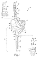
- FIG. 1 is a perspective view of an orthopaedic knee prosthesis, note a pair of optional sleeve components and a sleeve adaptor are shown exploded from the assembled knee prosthesis, with a portion of the stem adaptor being cut away for clarity of description;
- FIG. 2 is a perspective view of an orthopaedic surgical instrument tibial impaction guide
- FIG. 3 is a back-side perspective view of the surgical instrument of FIG. 2 ;
- FIG. 4 is a plan view of the surgical instrument of FIGS. 2-3 ;
- FIG. 5 is a back-side plan view of the surgical instrument of FIGS. 2-4 ;
- FIGS. 6-8 are views of a patient's tibia, the orthopaedic knee prosthesis of FIG. 1 , the orthopaedic surgical instrument of FIGS. 2-5 , and a group of orthopaedic instruments during the performance of an orthopaedic surgical procedure.
- FIG. 1 there is shown an implantable knee prosthesis 10 for use in the performance of an orthopaedic knee replacement procedure.
- the knee prosthesis 10 includes a femoral component 12 , a tibial tray 14 , a bearing 16 , and a number of stem components 18 .
- Each of the variously-sized stem components 18 may be secured to either the tibial tray 14 or the femoral component 12 .
- the tibial tray 14 is configured to be implanted into a surgically-prepared end of a patient's proximal tibia (not shown).
- the tibial tray 14 includes a platform 20 having an elongated stem post 22 extending inferiorly away from its inferior surface 24 .
- the tibial tray 14 includes a pair of keels 26 , 28 connecting the stem post 22 and the inferior surface 24 .
- the elongated tibial stem post 22 is configured to receive the stem components 18 .
- the stem post 22 of the tibial tray 14 has a tapered bore formed therein into which a tapered end of one of the stem components 18 may be advanced to taper lock the stem component 18 and the tibial tray 14 to one another.
- the stem component 18 may then be implanted into a surgically-prepared (e.g., reamed, punched, or broached) intramedullary canal.
- a surgically-prepared e.g., reamed, punched, or broached
- each of the keels 26 , 28 engages a slot defined in the intramedullary canal to secure the tibial tray 14 to the bone.
- the bearing 16 is securable to the tibial tray 14 .
- the bearing 16 may be snap-fit to the tibial tray 14 .
- the bearing 16 is fixed relative to the tibial tray 14 (i.e., it is not rotatable or moveable in the anterior/posterior or medial/lateral directions).
- the bearing 16 may be secured in a manner that allows it to rotate relative to the tibial tray 14 .
- the bearing 16 includes a lateral bearing surface 30 and a medial bearing surface 32 .
- the bearing surfaces 30 , 32 are configured to articulate with a lateral condyle surface 34 and a medial condyle surface 36 , respectively, of the femoral component 12 .
- the femoral component 12 is configured to be implanted into a surgically-prepared distal end of the patient's femur (not shown), and is configured to emulate the configuration of the patient's natural femoral condyles.
- the lateral condyle surface 34 and the medial condyle surface 36 are configured (e.g., curved) in a manner which mimics the condyles of the natural femur.
- the lateral condyle surface 34 and the medial condyle surface 36 are spaced apart from one another thereby defining an intercondylar notch therebetween.
- the condyle surfaces 34 , 36 are formed in a bearing surface 38 of the femoral component 12 .
- the femoral component 12 also includes an elongated stem post 40 , extending superiorly away from its opposite backside surface 42 .
- the elongated femoral stem post 40 is configured to receive the stem components 18 .
- the femoral component 12 has a tapered bore formed therein into which a tapered end of one of the stem components 18 may be advanced to taper lock the stem component 18 and the femoral component 12 to one another. In such a way, the stem component 18 may then be implanted into a surgically-prepared (e.g., reamed or broached) intramedullary canal of the patient's femur.
- a surgically-prepared e.g., reamed or broached
- the knee prosthesis 10 may also include a number of optional components such as a femoral sleeve component 44 , a tibial sleeve component 46 , and a stem adaptor 48 .
- the sleeve components 44 , 46 may be used to facilitate implantation of the femoral component 12 and the tibial tray 14 , respectively, in the presence of reduced bone quality in the patient's femur or tibia.
- the femoral sleeve component 44 is configured to be secured to the femoral component 12 so as to be positioned between the femoral component 12 and the stem component 18 .
- the inferior end 50 of the femoral sleeve component 44 has a bore (not shown) formed therein that may be taper locked to the outer surface of the femoral component's stem post 40 to lock the sleeve component 44 to the femoral component 12 .
- the opposite, superior end of the femoral sleeve component 44 is configured to receive the stem components 18 .
- the superior end of the femoral sleeve component 44 has a tapered bore 52 formed therein into which a tapered end of one of the stem components 18 may be advanced to taper lock the stem component 18 and the femoral sleeve component 44 to one another.
- the tibial sleeve component 46 may be embodied in a similar manner in which a bore formed in its superior end is taper locked to the stem post 22 of the tibial tray 14 , with its opposite, inferior end being configured to receive the stem components 18 and thereby lock the stem component 18 and the tibial sleeve component 46 to one another.
- the tibial sleeve component 46 may be used in conjunction with the stem adaptor 48 .
- the stem adaptor 48 is used to secure both the stem components 18 and the tibial sleeve component 46 to the tibial tray 14 .
- the stem adaptor 48 includes a tapered post 54 that is identical in shape and size to a tapered end of each of the stem components 18 .
- the tapered post 54 of the stem adaptor 48 may be advanced into the tibial tray's stem post 22 to lock the post 54 (and hence the stem adaptor 48 ) and the tibial tray 14 to one another.
- the tibial sleeve component 46 is configured to be secured to the stem adaptor 48 so as to be positioned between the tibial tray 14 and the stem component 18 .
- the tibial sleeve component 46 has a bore 56 formed therein that extends through its entire length and hence is open to both its superior end and its inferior end.
- the tibial sleeve component 46 may be advanced over the stem adaptor 48 such that the tapered sidewalls forming the bore 56 of the tibial sleeve component 46 engage to the tapered outer surface of the stem adaptor 48 to taper lock the sleeve component 46 to the stem adaptor 48 to one another.
- the inferior end of the stem adaptor 48 has a tapered bore 58 formed therein into which a tapered end of one of the stem components 18 may be advanced to taper lock the stem component 18 and the stem adaptor 48 to one another.
- the components of the knee prosthesis 10 that engage the natural bone may be constructed with an implant-grade biocompatible metal, although other materials may also be used.
- metals include cobalt, including cobalt alloys such as a cobalt chrome alloy, titanium, including titanium alloys such as a Ti6Al4V alloy, and stainless steel.
- Such a metallic component may also be coated with a surface treatment, such as hydroxyapatite, to enhance biocompatibility.
- the surfaces of the metallic components that engage the natural bone may be textured to facilitate securing the components to the bone. Such surfaces may also be porous coated to promote bone ingrowth for permanent fixation.
- the bearing 16 may be constructed with a material that allows for smooth articulation between the bearing 16 and the femoral component 12 , such as a polymeric material.
- a polymeric material is polyethylene such as ultrahigh molecular weight polyethylene (UHMWPE).
- Each of the stem components 18 includes an elongated, generally cylindrical stem body 60 .
- the elongated stem body 60 extends distally away from a tapered end 62 and terminates at rounded distal end 64 that defines the inferior-most surface of the stem component 18 when it is secured to a tibial tray 14 or the superior-most surface of the stem component 18 when it is secured to a femoral component 12 .
- a number of elongated flutes 66 are formed in the outer annularly-shaped surface 68 of the stem body 60 .
- the longitudinal axis of each of the flutes 66 is parallel to the longitudinal axis of the stem component 18 and hence is arranged in the superior/inferior direction.
- the stem component 18 may be provided in a number of different configurations in order to fit the needs of a given patient's anatomy.
- the stem component 18 may be configured in various different lengths to conform to the patient's anatomy (e.g., a relatively long stem component 18 for use with a long femur or tibia, a relatively short stem for use with a short femur or tibia, etcetera).
- the stem component 18 may be provided in three different lengths (e.g., 60 mm, 110 mm, and 160 mm).
- the stem component 18 may also be provided in varying body diameters to fit the needs of a given patient's anatomy.
- the body diameter of a given stem component 18 is the stem component's medial/lateral cross sectional width in the cylindrical midsection of the stem component's body 60 (i.e., not at its tapered end 62 or its distal tip 64 ).
- the stem component 18 may be provided in eight different diameters (e.g., 10 mm, 12 mm, 14 mm, 16 mm, 18 mm, 20 mm, 22 mm, and 24 mm) at each of the three different lengths (e.g., 60 mm, 110 mm, and 160 mm).
- 24 differently-sized stem components 18 may be provided in eight different diameters and three different lengths.
- the femoral component 12 , the tibial tray 14 , and the sleeve components 44 , 46 may be provided in various different sizes to fit the needs of a given patient's anatomy.
- each of the differently-sized stem components 18 is compatible with each of the differently-sized femoral components 12 , tibial trays 14 , and sleeve components 44 , 46 , along with the stem adaptor 48 .
- the geometry of the tapered bores of each of the differently-sized tibial trays 14 , the differently-sized femoral components 12 , the differently-sized sleeve components 44 , 46 , and the stem adaptor 48 is identical.
- the geometry of the tapered ends 62 of each of the differently-sized stem components 18 is identical.
- a tibial construct 70 When assembled for implantation, a tibial construct 70 is formed from the tibial tray 14 , a stem component 18 , and, optionally, the sleeve component 46 and/or the stem adaptor 48 . As described below, a surgeon may insert the tibial construct 70 into the patient's tibia in a surgical procedure. During installation, the tibial construct 70 should be correctly aligned with the tibia to ensure secure fixation.
- the impaction guide 100 includes a component-engaging side 102 that receives the platform 20 of the tibial tray 14 and a back side 104 opposite the component-engaging side 102 .
- the impaction guide 100 further includes a cup 106 positioned on the component-engaging side 102 and a collar 108 coupled to the cup 106 and positioned on the back side 104 .
- the cup 106 includes an outer surface 110 extending from the component-engaging side 102 to the collar 108 . As shown in FIGS. 2 and 4 , the cup 106 has an opening 112 defined therein that is positioned on the component-engaging side 102 .
- the cup 106 includes an inner wall 114 extending from the opening 112 to a substantially planar back wall 116 .
- the inner wall 114 is terraced and includes a number of stepped surfaces 120 .
- the opening 112 of the cup 106 has a kidney-shaped perimeter that follows the shape of the platform 20 of a tibial tray 14 .
- the perimeter of each stepped surface 120 defines a kidney-shape that is configured to receive the platform 20 of one size of tibial tray 14 .
- each of the stepped surfaces 120 has negative geometry that matches the perimeter of the platform 20 of one tibial tray. As a result, the platform 20 of that tibial tray 14 may be fitted onto that stepped surface 120 .
- each of the stepped surfaces 120 may be configured to receive one size of a group of differently-sized tibial trays 14 .
- the illustrative impaction guide 100 includes ten stepped surfaces 120 ; as such, the guide 100 is configured to receive ten differently-sized tibial trays 14 .
- the back wall 116 may also be configured to receive a tibial tray 14 .
- another embodiment of the impaction guide 100 may include nine stepped surfaces 120 and the back wall 116 collectively configured to receive the ten differently-sized tibial trays 14 .
- the cup 106 of the guide 100 includes an indicator configured to indicate location of the keels 26 , 28 of the tibial tray 14 when the tray is fitted into the cup 106 .
- the indicator includes a pair of slots 122 , 124 that extend through the outer surface 110 and the inner wall 114 and are positioned on the medial and lateral sides of the impaction guide 100 , respectively.
- the slots 122 , 124 extend through each of the stepped surfaces 120 , as shown in FIG. 2 .
- the illustrative impaction guide 100 includes two slots 122 , 124 , other embodiments of the impaction guide 100 the indicator may include a single slot on the medial side or the lateral side.
- the indicator may include a marking or etching in the outer surface 110 of the cup 106 that indicates the location of the keels 26 , 28 of the tibial tray 14 when the tray is fitted into the cup 106 .
- the impaction guide 100 includes a boss 126 that extends the outer surface 110 of the cup 106 on the anterior side. As shown in FIGS. 2-3 , the boss 126 has an elongated alignment bore 128 defined therein that extends from the component-engaging side 102 to the back side 104 .
- the alignment bore 128 may be used to secure another surgical instrument to the impaction guide 100 , for example, an alignment rod 144 as discussed below.
- the impaction guide 100 includes a collar 108 that extends away from the cup 106 .
- the collar 108 has a truncated cone shape, and an aperture 130 is defined in back end of the collar 108 .
- the aperture 130 is sized to receive an impaction handle 142 .
- the aperture 130 is defined by an inner wall 132 that extends from the back end of the collar 108 to a partition wall 134 .
- a circular central passageway 118 is defined through the back wall 116 of the cup 102 and the collar 108 .
- the passageway 118 connects the opening 112 of the cup 106 with the aperture 130 of the collar 108 .
- a slot 136 extends through the anterior side of the collar 108 and opens into the aperture 130 .
- the lower end of the slot 136 is defined by a recessed wall segment 140 , which is positioned below the partition wall 134 and extends posteriorly.
- the wall segment 140 and a flange 138 of the partition wall 134 cooperate to define a pocket 141 below the partition wall 134 .
- the central passageway 118 , flange 138 , and the pocket 141 cooperate to allow the impaction handle 142 to secure the impaction guide 100 .
- the impaction guide 100 may be attached to a tibial tray 14 .
- the tibial tray 14 is positioned with the platform 20 facing the component-engaging side 102 of the impaction guide 100 .
- the tibial tray 14 is oriented so that the platform 20 aligns with one of the stepped surfaces 120 having the corresponding size.
- the platform 20 engages the corresponding stepped surface 120 .
- the platform 20 is press-fit into the inner wall 114 against that stepped surface 120 , thereby securing the tibial tray 14 to the impaction guide 100 .
- the keels 26 , 28 of the tibial tray 14 are aligned with the indicator (i.e., the slots 122 , 124 ) of the impaction guide 100 , as shown in FIG. 6 .
- the slots 122 , 124 may be used as visual alignment guides for the keels 26 , 28 .
- the impaction guide 100 additionally may be attached to a number of surgical instruments, including an impaction handle 142 and an alignment rod 144 .
- the impaction handle 142 includes an elongated tool body 146 and an attachment mechanism 148 .
- the attachment mechanism 148 is configured to secure the impaction guide 100 to the impaction handle 142 , as described in detail below.
- the tool body 146 is formed from a metallic material, such as, for example, stainless steel or cobalt chromium.
- the tool body 146 extends from an attachment end 150 to a strike end 152 .
- a longitudinal axis 154 is defined between the attachment end 150 and the strike end 152 .
- the tool body 146 includes a housing 156 positioned at the attachment end 150 and a grip 158 positioned adjacent to the housing 156 toward the strike end 152 .
- the grip 158 is configured receive the hand of a surgeon or other user to allow the user to manipulate the impaction handle 142 . Accordingly, the grip 158 may be coated in a rubberized or textured material to improve grip stability. In some embodiments, the grip 158 may be formed as a separate unit from the housing 156 and assembled with the housing 156 to form the tool body 146 .
- the impaction handle 142 further includes a strike plate 160 attached to the grip 158 at the strike end 152 of the tool body 146 .
- the strike plate 160 is securely attached to the rest of the impaction handle 142 , for example by mechanically threading onto the end of the grip 158 .
- the strike plate 160 includes a durable surface suitable for use with a striking tool such as a mallet, sledge, or other impaction tool.
- the strike plate 160 is large enough to cover the grip 158 in order to shield the hand of the user. In use, the surgeon may impact the strike plate 160 to advance the tibial construct 70 into the intermedullary canal of the patient's tibia.
- the impaction handle 142 includes a guide pin (not shown) extending from the attachment end 150 that is configured to be received by the central passageway 118 of the impaction guide 100 .
- the attachment mechanism 148 of the impaction handle 142 includes the guide pin, a user-operated lever 162 extending outwardly from the housing 156 toward the strike end 152 , and a catch 164 extending outwardly from the housing 156 toward the attachment end 150 .
- the attachment mechanism 148 of the impaction handle 142 further includes an internal biasing element such as a spring (not shown) connecting the lever 162 and the catch 164 .
- the lever 162 is moveable between an extended, unclamped position and the clamped position closer to the grip 158 shown in FIG. 7 . When the lever 162 is moved by the user from the unclamped position to the clamped position, the catch 164 moves from a position apart from the guide pin to a position closer to the guide pin.
- the impaction guide 100 may be attached to the impaction handle 142 by aligning the attachment end 150 of the impaction handle 142 with the aperture 130 of the collar 108 .
- the housing 156 is keyed to assist in aligning the impaction handle 142 .
- the impaction handle 142 may then be advanced toward the guide 100 with the lever 162 in the unclamped position.
- the guide pin of the handle 142 is aligned with the central passageway 118 defined at the bottom of the aperture 130 .
- the guide pin may be advanced into the central passageway 118 until the attachment end 150 of the tool body 146 engages the partition wall 134 of the impaction guide 100 .
- the catch 164 passes over the flange 138 of the guide 100 to a position adjacent to the recessed wall segment 140 .
- the grip 158 and the lever 162 of the impaction handle 142 may be squeezed together to move the lever 162 to the clamped position, thereby causing the catch 164 to advance into the pocket 141 and engage the flange 138 .
- the impaction guide 100 is secured to the impaction handle 142 .
- the internal biasing element of the impaction handle 142 provides clamping force to secure the impaction guide 100 to the impaction handle 142 .
- the impaction guide 100 may also be attached to an alignment rod 144 .
- the alignment rod 144 includes an elongated shaft 166 extending from a rounded end 168 to a grip 170 .
- the grip 170 is wider than the shaft 166 , and may include a textured surface configured to allow the user to manipulate the alignment rod 144 .
- the alignment rod 144 is attached to the impaction guide 100 by inserting the rounded end 168 of the alignment rod 144 into the alignment bore 128 of the impaction guide 100 .
- the alignment rod 144 is advanced through the alignment bore 128 until the grip 170 engages the boss 126 of the impaction guide 100 , as shown in FIG. 8 .
- the boss 126 thus prevents the alignment rod 144 from continuing to advance through the alignment bore 128 .
- the shaft 166 and/or the grip 170 may include a tapered outer surface to lock the alignment rod 144 in position within the alignment bore 128 .
- the impaction guide 100 may be utilized during the performance of an orthopaedic surgical procedure similar to that shown in FIGS. 6-8 .
- the surgeon may insert an assembled tibial construct 70 into the impaction guide 100 and insert the tibial construct 70 into the intermedullary canal of the patient's tibia.
- the surgeon may adjust the axial alignment of the tibial construct 70 using the impaction guide 100 and the attached impaction handle 142 .
- the surgeon may also adjust the axial alignment of the tibial construct 70 using the impaction guide 100 and an attached alignment rod 144 .
- the surgeon initially prepares the intermedullary canal 202 of the patient's tibia 204 to receive the tibial construct 70 .
- the surgeon may insert an initial surgical reamer into the intermedullary canal 202 .
- the surgeon may use the reamer to drill and/or ream the intermedullary canal 202 to the depth and/or diameter required to receive the stem component 18 .
- Multiple drills or reamers may be used to increase the size of the opening 206 of the intermedullary canal 202 formed on the proximal surface 208 of the patient's tibia 204 .
- the surgeon may further insert a surgical broach into the intermedullary canal 202 to cut and/or shape the intermedullary canal 202 to receive the sleeve component 46 .
- the surgeon further prepares the intermedullary canal 202 by cutting one or more slots 210 in the proximal surface 208 , extending from the intermedullary canal 202 into the surrounding bone.
- the slots 210 are sized to receive the keels 26 , 28 of the tibial tray 14 , thereby stabilizing the tibial tray 14 when implanted.
- the surgeon may form the slots 210 by driving a keel punch tool into the proximal surface 208 of the tibia 204 .
- the intermedullary canal 202 is configured as shown in FIGS. 7 and 8 and is ready to receive the tibial construct 70 .
- the surgeon attaches the impaction guide 100 to the impaction handle 142 .
- the surgeon may advance the attachment end 150 of the impaction handle 142 into the aperture 130 of the impaction guide 100 .
- the surgeon advances the impaction handle 142 down the aperture 130 until a guide pin is received in the central passageway 118 of the impaction guide 100 and the attachment end 150 is seated against the partition wall 134 .
- the surgeon moves the lever 162 from the unclamped position to the clamped position to engage the catch 164 of the impaction handle 142 with the flange 138 of the impaction guide 100 , thereby securing the impaction guide 100 to the impaction handle 142 .
- the surgeon may also assemble the tibial construct 70 to be attached to the impaction guide 100 .
- the surgeon may select a tibial tray 14 and a stem component 18 of appropriate size for a particular patient, which may be determined using a trial reduction procedure. That is, the surgeon may try various combinations of prosthetic components to determine which implant size and configuration will have the best stability in flexion and extension while permitting the desired kinematics.
- the surgeon may select an appropriate sleeve component 46 or a stem adaptor 48 . This selection of components may be performed pre-operatively or intraoperatively, and may depend on the condition of the patient's tibia 204 .
- the surgeon may assemble the tibial construct 70 from the selected tibial tray 14 , stem component 18 , and optional sleeve component 46 and/or stem adaptor 48 .
- the surgeon may fit the platform 20 of the selected tibial tray 14 into one of the stepped surfaces 120 of the impaction guide 100 . As described above, the surgeon press-fits the platform 20 into the stepped surface 120 having matching size.
- the surgeon may insert the stem component 18 into the surgically prepared intermedullary canal 202 of the tibia 204 , as shown in FIG. 7 .
- the surgeon may rotate the impaction handle 142 axially about its longitudinal axis 154 to align the keels 26 , 28 of the tibial tray 14 with the slots 210 of the intermedullary canal 202 .
- the surgeon may rotate the impaction handle 142 —and therefore also rotate the impaction guide 100 and the tibial construct 70 —until the slots 210 of the intermedullary canal 202 are visible through the slots 122 , 124 defined in the impaction guide 100 , as indicated by sight line 212 . Because the slots 122 , 124 align with the keels 26 , 28 , when the slots 210 are visible through the slots 122 , 124 , the tibial construct 70 is properly aligned with the slots 210 .
- surgeon may draw or etch one or more lines on the proximal end of the tibia, which extend from (and are aligned with) the slot to the edge of the tibia to provide an indicator on the bone of the slot locations.
- the surgeon may use an attached alignment rod 144 to align the impaction guide 100 . If so, prior to inserting the stem component 18 into the intermedullary canal 202 , the surgeon may make a marking 214 on the anterior-most aspect of the tibia 204 (see FIG. 6 ). The surgeon may make the marking 214 using a marking tool such as a surgical marking pen, an electrosurgical generator tool, or any other surgical tool capable of making a mark on the tibia 204 . As shown in FIG. 8 , the surgeon may attach the alignment rod 144 to the impaction guide 100 by sliding the shaft 166 of the alignment rod 144 through the alignment bore 128 from the back side 104 of the impaction guide 100 .
- the surgeon may rotate the impaction handle 142 axially about its longitudinal axis 154 to align the shaft 166 of the alignment rod 144 with the marking 214 on the tibia 204 .
- the surgeon may rotate the impaction handle 142 —and therefore also rotate the impaction guide 100 and the tibial construct 70 —until the shaft 166 , the marking 214 , and the center of the intermedullary canal 202 lie in a common imaginary plane 216 .
- Aligning the alignment rod 144 with the marking 214 also aligns the keels 26 , 28 with the slots 210 of the intermedullary canal 202 , because the keels 26 , 28 and the slots 210 share the same relative alignment to the alignment rod 144 and the marking 214 , respectively.
- the surgeon may then drive the tibial construct 70 into the tibia 204 along the intermedullary canal 202 by striking the strike plate 160 of the impaction handle 142 with mallet, sledge, or other impaction tool.
- the flutes 66 of the stem component 18 cut into the patient's tibia 204 to stabilize the tibial construct 70 in the intermedullary canal 202 .
- the surgeon may use the impaction guide 100 to align the tibial construct 70 as it is inserted into the intermedullary canal 202 and as it is initially driven into the tibia 204 , both when the keels 26 , 28 of the tibial tray 14 are some distance from the proximal surface 208 of the tibia 204 .
- the surgeon may rotate the impaction handle 142 axially to align the tibial construct 70 while the stem component 18 is partially inserted in the intermedullary canal 202 , as long as the stem component 18 has not been advanced too far into the intermedullary canal 202 .
- the surgeon may remove the impaction guide 100 from the platform 20 and continue implantation of the knee prosthesis 10 .
- the impaction guide may be utilized without the impaction handle.
- the impaction guide attached to the tibial construct 70 , and the tibial construct 70 aligned with the patient's tibia by hand.
Landscapes
- Health & Medical Sciences (AREA)
- Orthopedic Medicine & Surgery (AREA)
- Transplantation (AREA)
- Heart & Thoracic Surgery (AREA)
- Oral & Maxillofacial Surgery (AREA)
- Cardiology (AREA)
- Engineering & Computer Science (AREA)
- Biomedical Technology (AREA)
- Physical Education & Sports Medicine (AREA)
- Vascular Medicine (AREA)
- Life Sciences & Earth Sciences (AREA)
- Animal Behavior & Ethology (AREA)
- General Health & Medical Sciences (AREA)
- Public Health (AREA)
- Veterinary Medicine (AREA)
- Prostheses (AREA)
Abstract
Description
Claims (20)
Priority Applications (1)
| Application Number | Priority Date | Filing Date | Title |
|---|---|---|---|
| US13/833,208 US9737408B2 (en) | 2013-03-15 | 2013-03-15 | Tibial impaction guide surgical instrument and method of using same |
Applications Claiming Priority (1)
| Application Number | Priority Date | Filing Date | Title |
|---|---|---|---|
| US13/833,208 US9737408B2 (en) | 2013-03-15 | 2013-03-15 | Tibial impaction guide surgical instrument and method of using same |
Publications (2)
| Publication Number | Publication Date |
|---|---|
| US20140277540A1 US20140277540A1 (en) | 2014-09-18 |
| US9737408B2 true US9737408B2 (en) | 2017-08-22 |
Family
ID=51531351
Family Applications (1)
| Application Number | Title | Priority Date | Filing Date |
|---|---|---|---|
| US13/833,208 Active 2036-03-22 US9737408B2 (en) | 2013-03-15 | 2013-03-15 | Tibial impaction guide surgical instrument and method of using same |
Country Status (1)
| Country | Link |
|---|---|
| US (1) | US9737408B2 (en) |
Cited By (4)
| Publication number | Priority date | Publication date | Assignee | Title |
|---|---|---|---|---|
| US20190038430A1 (en) * | 2012-09-28 | 2019-02-07 | Depuy Ireland Unlimited Company | Surgical instrument and method of use |
| US11684398B2 (en) | 2019-01-29 | 2023-06-27 | Howmedica Osteonics Corp. | Press fit stem |
| EP4389078A1 (en) * | 2022-12-22 | 2024-06-26 | Zimmer, Inc. | Segmented keel for prosthetic implant having a stem |
| US12369930B2 (en) | 2022-06-20 | 2025-07-29 | Zimmer, Inc. | Systems for guided reaming of complex shapes |
Families Citing this family (12)
| Publication number | Priority date | Publication date | Assignee | Title |
|---|---|---|---|---|
| US10335285B2 (en) | 2016-10-13 | 2019-07-02 | Howmedica Osteonics Corp. | Reviseable stemless prostheses and methods |
| US12083027B2 (en) | 2017-03-02 | 2024-09-10 | Optimotion Implants LLC | Universal femoral trial system and methods |
| US10905436B2 (en) | 2017-03-02 | 2021-02-02 | Optimotion Implants, Llc | Knee arthroplasty systems and methods |
| US11406502B2 (en) | 2017-03-02 | 2022-08-09 | Optimotion Implants LLC | Orthopedic implants and methods |
| US10987225B2 (en) | 2017-08-04 | 2021-04-27 | Zimmer, Inc. | Systems and methods for attaching sleeve or cone in prosthetic implant having a stem |
| WO2019075066A1 (en) * | 2017-10-11 | 2019-04-18 | Zimmer, Inc. | Impaction cradle |
| CN111212616B (en) * | 2017-10-13 | 2022-04-12 | 捷迈有限公司 | Revision knee arthroplasty methods and instruments |
| CN112789010B (en) | 2018-10-04 | 2025-01-28 | 德普伊爱尔兰无限公司 | Prosthesis extraction system |
| CN109394300B (en) * | 2018-11-28 | 2023-08-04 | 陕西四正医疗器械有限责任公司 | Marrow cavity file |
| CN112618114A (en) * | 2020-11-27 | 2021-04-09 | 北京市春立正达医疗器械股份有限公司 | Tantalum metal trabecular femoral condyle prosthesis and knee joint replacement body |
| CA3243955A1 (en) * | 2021-12-21 | 2023-06-29 | Depuy Ireland Unlimited Company | Orthopaedic knee cone components for use in an orthopaedic surgical procedure and instruments and methods for installing the same |
| CN114795601B (en) * | 2022-06-29 | 2022-09-02 | 深圳市迈捷生命科学有限公司 | Implant structure for fixing orthopaedic prosthesis |
Citations (7)
| Publication number | Priority date | Publication date | Assignee | Title |
|---|---|---|---|---|
| USD372309S (en) | 1995-07-06 | 1996-07-30 | Zimmer, Inc. | Orthopaedic broach impactor |
| US20080119941A1 (en) * | 2006-11-22 | 2008-05-22 | Jai-Gon Seo | Tibia impacter |
| US20090036909A1 (en) * | 2005-04-01 | 2009-02-05 | Perry Lance D | Femoral component holder |
| US20120123429A1 (en) * | 2009-07-04 | 2012-05-17 | Depuy (Ireland) | Surgical instrument |
| US20130006252A1 (en) * | 2011-06-30 | 2013-01-03 | Waite Ii David W | Method of surgically preparing a tibia for implantation of a prosthetic component |
| US20140094821A1 (en) * | 2012-09-28 | 2014-04-03 | Depuy Products, Inc. | Impactor for Securing an Implant to a Bone Surface |
| US20140094812A1 (en) * | 2012-09-28 | 2014-04-03 | Depuy Products, Inc. | Surgical Instrument and Method of Use |
-
2013
- 2013-03-15 US US13/833,208 patent/US9737408B2/en active Active
Patent Citations (7)
| Publication number | Priority date | Publication date | Assignee | Title |
|---|---|---|---|---|
| USD372309S (en) | 1995-07-06 | 1996-07-30 | Zimmer, Inc. | Orthopaedic broach impactor |
| US20090036909A1 (en) * | 2005-04-01 | 2009-02-05 | Perry Lance D | Femoral component holder |
| US20080119941A1 (en) * | 2006-11-22 | 2008-05-22 | Jai-Gon Seo | Tibia impacter |
| US20120123429A1 (en) * | 2009-07-04 | 2012-05-17 | Depuy (Ireland) | Surgical instrument |
| US20130006252A1 (en) * | 2011-06-30 | 2013-01-03 | Waite Ii David W | Method of surgically preparing a tibia for implantation of a prosthetic component |
| US20140094821A1 (en) * | 2012-09-28 | 2014-04-03 | Depuy Products, Inc. | Impactor for Securing an Implant to a Bone Surface |
| US20140094812A1 (en) * | 2012-09-28 | 2014-04-03 | Depuy Products, Inc. | Surgical Instrument and Method of Use |
Cited By (6)
| Publication number | Priority date | Publication date | Assignee | Title |
|---|---|---|---|---|
| US20190038430A1 (en) * | 2012-09-28 | 2019-02-07 | Depuy Ireland Unlimited Company | Surgical instrument and method of use |
| US10898347B2 (en) * | 2012-09-28 | 2021-01-26 | Depuy Ireland Unlimited Company | Surgical instrument and method of use |
| US11684398B2 (en) | 2019-01-29 | 2023-06-27 | Howmedica Osteonics Corp. | Press fit stem |
| US12329426B2 (en) | 2019-01-29 | 2025-06-17 | Howmedica Osteonics Corp. | Press fit stem |
| US12369930B2 (en) | 2022-06-20 | 2025-07-29 | Zimmer, Inc. | Systems for guided reaming of complex shapes |
| EP4389078A1 (en) * | 2022-12-22 | 2024-06-26 | Zimmer, Inc. | Segmented keel for prosthetic implant having a stem |
Also Published As
| Publication number | Publication date |
|---|---|
| US20140277540A1 (en) | 2014-09-18 |
Similar Documents
| Publication | Publication Date | Title |
|---|---|---|
| US9737408B2 (en) | Tibial impaction guide surgical instrument and method of using same | |
| US11006968B2 (en) | Method and orthopaedic surgical instrument system for surgically preparing a patient's bone | |
| US11517448B2 (en) | Method for preparing a patient's femur in an orthopaedic joint replacement procedure | |
| EP2939615A1 (en) | Tibial trial system for a knee prosthesis | |
| AU2014201412B2 (en) | Surgical instrument and method of use | |
| US20190247063A1 (en) | Orthopaedic surgical instrument system and method for preparing a patient's calcar | |
| EP2777553B1 (en) | Instrument assembly for implanting a stem component of a knee prosthesis | |
| EP2777620A1 (en) | Orthopaedic knee prosthesis | |
| US12220135B2 (en) | Orthopaedic surgical instrument system and method including a stem trial component | |
| US20190247061A1 (en) | Orthopaedic surgical instrument system and method for preparing a patient's calcar |
Legal Events
| Date | Code | Title | Description |
|---|---|---|---|
| AS | Assignment |
Owner name: DEPUY SYNTHES PRODUCTS, LLC, MASSACHUSETTS Free format text: ASSIGNMENT OF ASSIGNORS INTEREST;ASSIGNORS:LESZKO, FILIP;LEE, JONATHAN C.;TSUKAYAMA, CRAIG S.;SIGNING DATES FROM 20140204 TO 20140210;REEL/FRAME:033476/0345 |
|
| AS | Assignment |
Owner name: DEPUY (IRELAND), IRELAND Free format text: ASSIGNMENT OF ASSIGNORS INTEREST;ASSIGNOR:DEPUY SYNTHES PRODUCTS, LLC;REEL/FRAME:034014/0871 Effective date: 20141015 |
|
| AS | Assignment |
Owner name: DEPUY IRELAND UNLIMITED COMPANY, IRELAND Free format text: ASSIGNMENT OF ASSIGNORS INTEREST;ASSIGNOR:DEPUY (IRELAND);REEL/FRAME:042368/0860 Effective date: 20160812 |
|
| STCF | Information on status: patent grant |
Free format text: PATENTED CASE |
|
| MAFP | Maintenance fee payment |
Free format text: PAYMENT OF MAINTENANCE FEE, 4TH YEAR, LARGE ENTITY (ORIGINAL EVENT CODE: M1551); ENTITY STATUS OF PATENT OWNER: LARGE ENTITY Year of fee payment: 4 |
|
| MAFP | Maintenance fee payment |
Free format text: PAYMENT OF MAINTENANCE FEE, 8TH YEAR, LARGE ENTITY (ORIGINAL EVENT CODE: M1552); ENTITY STATUS OF PATENT OWNER: LARGE ENTITY Year of fee payment: 8 |