US9736472B2 - Motion vector processing - Google Patents
Motion vector processing Download PDFInfo
- Publication number
- US9736472B2 US9736472B2 US14/238,494 US201214238494A US9736472B2 US 9736472 B2 US9736472 B2 US 9736472B2 US 201214238494 A US201214238494 A US 201214238494A US 9736472 B2 US9736472 B2 US 9736472B2
- Authority
- US
- United States
- Prior art keywords
- camera view
- motion vector
- current
- view
- vector predictor
- Prior art date
- Legal status (The legal status is an assumption and is not a legal conclusion. Google has not performed a legal analysis and makes no representation as to the accuracy of the status listed.)
- Active, expires
Links
Images


Classifications
-
- H04N19/00684—
-
- H—ELECTRICITY
- H04—ELECTRIC COMMUNICATION TECHNIQUE
- H04N—PICTORIAL COMMUNICATION, e.g. TELEVISION
- H04N19/00—Methods or arrangements for coding, decoding, compressing or decompressing digital video signals
- H04N19/50—Methods or arrangements for coding, decoding, compressing or decompressing digital video signals using predictive coding
- H04N19/503—Methods or arrangements for coding, decoding, compressing or decompressing digital video signals using predictive coding involving temporal prediction
- H04N19/51—Motion estimation or motion compensation
- H04N19/513—Processing of motion vectors
-
- H—ELECTRICITY
- H04—ELECTRIC COMMUNICATION TECHNIQUE
- H04N—PICTORIAL COMMUNICATION, e.g. TELEVISION
- H04N19/00—Methods or arrangements for coding, decoding, compressing or decompressing digital video signals
- H04N19/10—Methods or arrangements for coding, decoding, compressing or decompressing digital video signals using adaptive coding
- H04N19/102—Methods or arrangements for coding, decoding, compressing or decompressing digital video signals using adaptive coding characterised by the element, parameter or selection affected or controlled by the adaptive coding
- H04N19/103—Selection of coding mode or of prediction mode
- H04N19/105—Selection of the reference unit for prediction within a chosen coding or prediction mode, e.g. adaptive choice of position and number of pixels used for prediction
-
- H—ELECTRICITY
- H04—ELECTRIC COMMUNICATION TECHNIQUE
- H04N—PICTORIAL COMMUNICATION, e.g. TELEVISION
- H04N19/00—Methods or arrangements for coding, decoding, compressing or decompressing digital video signals
- H04N19/10—Methods or arrangements for coding, decoding, compressing or decompressing digital video signals using adaptive coding
- H04N19/102—Methods or arrangements for coding, decoding, compressing or decompressing digital video signals using adaptive coding characterised by the element, parameter or selection affected or controlled by the adaptive coding
- H04N19/103—Selection of coding mode or of prediction mode
- H04N19/109—Selection of coding mode or of prediction mode among a plurality of temporal predictive coding modes
-
- H—ELECTRICITY
- H04—ELECTRIC COMMUNICATION TECHNIQUE
- H04N—PICTORIAL COMMUNICATION, e.g. TELEVISION
- H04N19/00—Methods or arrangements for coding, decoding, compressing or decompressing digital video signals
- H04N19/50—Methods or arrangements for coding, decoding, compressing or decompressing digital video signals using predictive coding
- H04N19/503—Methods or arrangements for coding, decoding, compressing or decompressing digital video signals using predictive coding involving temporal prediction
- H04N19/51—Motion estimation or motion compensation
- H04N19/513—Processing of motion vectors
- H04N19/517—Processing of motion vectors by encoding
- H04N19/52—Processing of motion vectors by encoding by predictive encoding
-
- H—ELECTRICITY
- H04—ELECTRIC COMMUNICATION TECHNIQUE
- H04N—PICTORIAL COMMUNICATION, e.g. TELEVISION
- H04N19/00—Methods or arrangements for coding, decoding, compressing or decompressing digital video signals
- H04N19/50—Methods or arrangements for coding, decoding, compressing or decompressing digital video signals using predictive coding
- H04N19/503—Methods or arrangements for coding, decoding, compressing or decompressing digital video signals using predictive coding involving temporal prediction
- H04N19/51—Motion estimation or motion compensation
- H04N19/56—Motion estimation with initialisation of the vector search, e.g. estimating a good candidate to initiate a search
-
- H—ELECTRICITY
- H04—ELECTRIC COMMUNICATION TECHNIQUE
- H04N—PICTORIAL COMMUNICATION, e.g. TELEVISION
- H04N19/00—Methods or arrangements for coding, decoding, compressing or decompressing digital video signals
- H04N19/50—Methods or arrangements for coding, decoding, compressing or decompressing digital video signals using predictive coding
- H04N19/503—Methods or arrangements for coding, decoding, compressing or decompressing digital video signals using predictive coding involving temporal prediction
- H04N19/51—Motion estimation or motion compensation
- H04N19/573—Motion compensation with multiple frame prediction using two or more reference frames in a given prediction direction
-
- H—ELECTRICITY
- H04—ELECTRIC COMMUNICATION TECHNIQUE
- H04N—PICTORIAL COMMUNICATION, e.g. TELEVISION
- H04N19/00—Methods or arrangements for coding, decoding, compressing or decompressing digital video signals
- H04N19/50—Methods or arrangements for coding, decoding, compressing or decompressing digital video signals using predictive coding
- H04N19/503—Methods or arrangements for coding, decoding, compressing or decompressing digital video signals using predictive coding involving temporal prediction
- H04N19/51—Motion estimation or motion compensation
- H04N19/577—Motion compensation with bidirectional frame interpolation, i.e. using B-pictures
-
- H—ELECTRICITY
- H04—ELECTRIC COMMUNICATION TECHNIQUE
- H04N—PICTORIAL COMMUNICATION, e.g. TELEVISION
- H04N19/00—Methods or arrangements for coding, decoding, compressing or decompressing digital video signals
- H04N19/50—Methods or arrangements for coding, decoding, compressing or decompressing digital video signals using predictive coding
- H04N19/597—Methods or arrangements for coding, decoding, compressing or decompressing digital video signals using predictive coding specially adapted for multi-view video sequence encoding
Definitions
- the present embodiments generally relate to processing of motion vectors, and in particular to prediction and decoding of such motion vectors.
- H.264 also denoted Moving Picture Experts Group-4 (MPEG-4) Advanced Video Coding (AVC)
- MPEG-4 Moving Picture Experts Group-4
- AVC Advanced Video Coding
- VCL video coding layer
- NAL network abstraction layer
- H.264 is block-based, i.e. a video frame is processed in macroblock (MB) units, which are 16 ⁇ 16 pixel blocks that may be further divided into sub-macroblocks (sMB).
- MB macroblock
- sMB sub-macroblocks
- MC motion compensation
- MC motion compensation
- Final reconstruction can be made by adding the predicting pixel values together with the residue pixel values.
- motion search is usually done at the encoder side. It tries to find lowest sum of squared differences (SSD) or sum of absolute differences (SAD) between the current pixel block and possible reference pixel blocks.
- SSD sum of squared differences
- SAD sum of absolute differences
- the outcome of the motion search is a reference index signaling which reference frame it refers to and an offset vector called motion vector (MV) pointing to the reference area.
- MV is an important and consuming component in the video bitstream. For video coded with high Quantization Parameter (QP), it can take up to over 50% of the bitrate.
- QP Quantization Parameter
- MVs are not directly coded into bitstream since there are redundancies to exploit between MVs. Neighboring MVs often have high correlations and MVs with similar length and direction are often clustering together. These clustered MVs could correspond to local motion where an object is moving or global motion where there is a panning.
- a MV prediction is done first to reduce the amount of data so that only the difference between the MV and the MV predictor is coded.
- a median predictor is generated by taking the median value of the MVs from the pixel block to the left, above and top-right. The process is done for the horizontal and vertical MV component respectively.
- Multi-View Video Coding (MVC)
- a multi-view representation represents the content from different camera perspectives or views, a particular case being the “stereoscopic video” case, where the scene is captured from two cameras that have the same or a similar distance as the human eye.
- suitable display technologies to present the “stereoscopic” content to the viewer, perception of depth can be provided to the viewer.
- MVC is a video coding standard that can be used to compress multi-view video representations. High compression efficiency is achieved by eliminating redundant information between different layers. MVC is based on the AVC standard and consequently MVC shares most of the AVC structure.
- a reference picture list is a collection of pictures that can be used for prediction. They are normally sorted in an order based on how close they are to the current frame. In AVC, all the reference pictures in the list are from the same view. In MVC, apart from reference pictures from the same view, there are also reference pictures from other views. Hence the first step of MVC reference picture list construction process is exactly the same as in AVC, and the difference lies in that inter-view reference pictures are appended afterwards. Due to complexity consideration, it is only allowed to add frames at the same instance in time from other views to the list in MVC.
- High Efficiency Video Coding (HEVC)
- HEVC is a next generation video coding standard that is currently under standardization process. HEVC aims to substantially improve coding compared to AVC, especially for high resolution video sequences. The initial focus of the HEVC development is on mono video, i.e. a single view.
- VCEG Contribution [1] described a new technology denoted as motion vector competition.
- the key concept of this technology is to take the MV from the neighboring pixel blocks which are often highly correlated to the current MV to form a list of candidate MVs, where neighboring pixel blocks can be either spatial neighbors, i.e. same frame, or temporal neighbors, i.e. different frames.
- These candidate MVs are scaled according to their temporal distance to their respective reference frames. Only one candidate MV from the list is selected to be the predictor based on rate-distortion (RD) criteria, and the corresponding index entry to the list is transmitted in the bitstream.
- RD rate-distortion
- Motion vector competition in general improves video coding performance as compared to median MV prediction and is therefore suggested for usage in HEVC.
- the selected candidate MVs In motion vector competition, the selected candidate MVs generally need to be scaled before being put into the candidate list since it does not necessarily have the same reference distance as the reference distance of the current pixel block for which the MV prediction is made.
- the term “reference distance” refers to the difference of picture order count (POC) between the frame with the MV and the frame that the MV points to.
- POC picture order count
- the current pixel block is testing inter prediction mode which uses reference areas from frame 0 as reference.
- Three candidate MV predictors are shown in the figure, they are MV B from a spatial neighboring pixel block in the current frame, and MV A and C from temporal collocated blocks before and after the current frame respectively.
- a scaling factor is used on these candidate MV predictors before they are adopted into the candidate list.
- the scaling factor formula is:
- Each candidate MV predictor is scaled up or down according to the calculated scaling factor. These scaled MV predictors are shown at the bottom of FIG. 1 .
- a motion vector when applying motion vector competition to a multi-view video sequence, a motion vector can point to a frame with the same POC but in another view or a candidate MV predictor could point to a frame with the same POC in another view.
- the numerator and the denominator, respective, of the above presented scaling formula is zero. This results in a zero scaling factor or an indefinite scaling factor, respectively.
- suboptimal compression performance can occur when selecting candidate MV predictors when having the possibility of using not only spatially and temporally neighboring candidate MV predictors but also MVs from other views.
- An aspect of the embodiments defines a method of motion vector prediction for multi-view video coding of video content from multiple camera views.
- the method comprises estimating a motion vector for a current pixel block in a current frame of a current camera view.
- the motion vector identifies a reference pixel area in a reference frame of a reference camera view that is different from the current camera view.
- At least one candidate motion vector predictor associated with a pixel block in a first frame of a first camera view and identifying a pixel area in a first reference frame of a first reference camera view different from said first camera view is provided.
- the method further comprises determining a scaling factor for the at least one candidate motion vector predictor based on a baseline distance between the current camera view and the reference camera view and a baseline distance between the first camera view and the first reference camera view.
- a scaled candidate motion vector predictor is determined for the at least one candidate motion vector predictor based on the candidate motion vector predictor multiplied by the scaling factor.
- a motion vector predictor is determined for the motion vector based on the at least one scaled candidate motion vector predictor.
- This aspect of the embodiments further defines a device for motion vector prediction for multi-view video coding of video content from multiple camera views.
- the device comprises a motion vector estimator configured to estimate a motion vector for a current pixel block in a current frame of a current camera view.
- the motion vector identifies a reference pixel area in a reference frame of a reference camera view that is different from current camera view.
- a predictor provider is configured to provide at least one candidate motion vector predictor associated with a pixel block in a first frame of a first camera view and identifying a pixel area in a first reference frame of a first reference camera view different from the first camera view.
- the device also comprises a scaling factor determiner configured to determine a scaling factor for the at least one candidate motion vector predictor based on a baseline distance between the current camera view and the reference camera view and a baseline distance between the first camera view and the first reference camera view.
- a scaled predictor determiner is configured to determine a scaled candidate motion vector predictor for the at least one candidate motion vector predictor based on the candidate motion vector predictor multiplied by the scaling factor.
- a predictor determiner is configured to determine a motion vector predictor for the motion vector based on the at least one scaled candidate motion vector predictor.
- the present aspect of the embodiments also defines a computer program for predicting motion vectors for multi-view video coding of video content from multiple camera views.
- the computer program comprises code means which when run on a computer causes the computer to estimate a motion vector for a current pixel block in a current frame of a current camera view.
- the motion vector identifies a reference pixel area in a reference frame of a reference camera view different from the current camera view.
- the computer is caused to provide at least one candidate motion vector predictor associated with a pixel block in a first frame of a first camera view and identifying a pixel area in a first reference frame of a first reference camera view that is different from the first camera view.
- the computer is further caused to determine a scaling factor for the at least one candidate motion vector predictor based on a baseline distance between the current camera view and the reference camera view and a baseline distance between the first camera view and the first reference camera view.
- the computer is further caused to determine a scaled candidate motion vector predictor for the at least one candidate motion vector predictor based on the candidate motion vector predictor multiplied by the scaling factor and determine a motion vector predictor for the motion vector based on the at least one scaled candidate motion vector predictor.
- a related aspect of the embodiments defines a method of motion vector decoding for encoded multi-view video from multiple camera views.
- the method comprises providing a reference frame index for a current pixel block in a current frame of a current camera view.
- the reference frame index identifies a reference frame of a reference camera view that is different from the current camera view.
- At least one candidate motion vector predictor associated with a pixel block in a first frame of a first camera view and identifying a pixel area in a first reference frame of a first reference camera view different from the first camera view is identified for the current pixel block.
- the method also comprises determining a respective scaling factor based on a baseline distance between the current camera view and the reference camera view and a baseline distance between the first camera view and the first reference camera view for the at least one candidate motion vector predictor.
- a candidate list comprising at least one scaled candidate motion vector predictor formed based on the at least one candidate motion vector predictor multiplied by the respective scaling factor is generated.
- the method further comprises determining a motion vector for the current pixel block based on a scalded candidate motion vector predictor of the candidate list.
- This related aspect of the embodiments further defines a device for motion vector decoding for encoded multi-view video from multiple camera views.
- the device comprises an index provider configured to provide a reference frame index for a current pixel block in a current frame of a current camera view.
- the reference frame index identifies a reference frame of a reference camera view that is different from the current camera view.
- a predictor identifier is configured to identify at least one candidate motion vector predictor associated with a pixel block in a first frame of a first camera view and identifying a pixel area in a first reference frame of a first reference camera view different from the first camera view for the current pixel block.
- the device also comprises a scaling factor determiner configured to determine a respective scaling factor for the at least one candidate motion vector predictor based on a baseline distance between the current camera view and the reference camera view and a baseline distance between the first camera view and the first reference camera view.
- a list generator is configured to generate a candidate list comprising at least one scaled candidate motion vector predictor formed based on the at least one candidate motion vector predictor multiplied by the respective scaling factor.
- the device further comprises a vector determiner configured to determine a motion vector for the current pixel block based on a scaled candidate motion vector predictor of the candidate list.
- the present related aspect of the embodiments also defines a computer program for decoding motion vectors for encoded multi-view video from multiple camera views.
- the computer program comprises code means which when run on a computer causes the computer to provide a reference frame index for a current pixel block in a current frame of a current camera view.
- the reference frame index identifies a reference frame of a reference camera view different from the current camera view.
- the computer is caused to identify at least one candidate motion vector predictor associated with a pixel block in a first frame of a first camera view and identifying a pixel area in a first reference frame of a first reference camera view different from the first camera view for the current pixel block.
- the computer is also caused to determine a respective scaling factor based on a baseline distance between the current camera view and the reference camera view and a baseline distance between the first camera view and the first reference camera view for the at least one candidate motion vector predictor.
- the computer is further caused to generate a candidate list comprising at least one scaled candidate motion vector predictor formed based on the at least one candidate motion vector predictor multiplied by the respective scaling factor and determine a motion vector for the current pixel block based on a scaled candidate motion vector predictor of the candidate list.
- Determining the scaling factors for the candidate MV predictors to be based on and proportional to the baseline distance for a varying baseline distance scenario improves the coding efficiency of the motion vectors.
- FIG. 1 schematically illustrates the concept of calculating scaling factors for motion vector candidates using motion vector competition
- FIG. 2 schematically illustrates the concept of having different motion vector types
- FIG. 3 illustrates a set of changing baseline distances between camera views
- FIG. 4 is a flow diagram illustrating a method of motion vector prediction according to an embodiment
- FIG. 5 is a schematic block diagram of a device for motion vector prediction according to an embodiment
- FIG. 6 is a schematic block diagram illustrating a computer comprising a computer program product with a computer program for motion vector prediction according to an embodiment
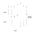
- FIG. 7 illustrates motion vector prediction according to an embodiment for a multi-view video stream
- FIG. 8 is a flow diagram illustrating a method of motion vector decoding according to an embodiment
- FIG. 9 is a schematic block diagram of a device for motion vector decoding according to an embodiment
- FIG. 10 is a schematic block diagram illustrating a computer comprising a computer program product with a computer program for motion vector decoding according to an embodiment
- FIG. 11 is a schematic block diagram illustrating an encoder according to an embodiment
- FIG. 12 is a schematic block diagram illustrating a decoder according to an embodiment.
- FIG. 13 is a schematic block diagram of a media terminal exemplified by a user equipment according to an embodiment.
- the present embodiments generally relate to the processing of motion vectors and in particular to motion vector prediction for multi-view video coding and motion vector decoding for encoded multi-view video.
- the embodiments enable an efficient and accurate motion vector prediction and decoding in applications where multiple camera views are present for recording scenes from different views.
- the embodiments can advantageously be applied to the previously described HEVC standard using multi-view video coding and decoding.
- the embodiments can also be used in connection with other multi-view video coding and decoding standards and schemes utilizing motion vector prediction.
- the embodiments can be used in connection with MVC in order to enable motion vector prediction and decoding.
- the embodiments are advantageously used as a complement to motion vector competition in order to enable usage of motion vector competition also for multi-view video coding and decoding.
- the embodiments as disclosed herein are, however, not limited to HEVC, MVC or indeed motion vector competition. In clear contrast, the embodiments can be used to predict and decode motion vectors in connection with any multi-view video application.
- motion vectors are used in the context of pixel prediction from a reference frame at a reference point in time to a current frame at a current point in time.
- the term motion vector is sometimes used in video coding with multiple views to refer to prediction from a reference frame in a current view to a current frame in the current view, i.e. “pure temporal prediction”.
- the term “disparity vector” is sometimes used.
- motion vector is used both in the context of “pure temporal prediction”, “pure inter-view prediction”, and combinations thereof, i.e. including in the context of pixel prediction from a reference view at a reference point in time to a current view at a current point in time.
- FIG. 2 When applying motion vector prediction in connection with multi-view video coding, such as doing the previously mentioned motion vector competition, various types of motion vectors are possible. This is schematically illustrated in FIG. 2 .
- the motion vector A in FIG. 2 points from a current frame towards a reference frame backward in time (or forward in time) in a current view. This corresponds to a so-called temporal motion vector type and it generally represents a true motion of video content.
- Motion vector C points to a reference frame at the point of time as the current frame but in another camera view. This is a so-called inter-view motion vector type and generally represents the disparity between the two views, i.e. view 0 and view 1.
- Motion vector B points to a reference frame at a different point of time as compared to the current frame but also in another camera view.
- This motion vector typically represents a combination of true motion and disparity and could be regarded as being of both the temporal and the inter-view motion vector type.
- a further optional variant is a so-called spatial motion vector type represented by the motion vector D, which points to coded pixel area in the current frame itself. Such a motion vector type can be considered to represent a repetitive pattern.
- FIG. 3 illustrates this concept.
- the baseline distances are changing for a stereoscopic representation, i.e. having two camera views.
- the baseline distances are the same for frame 0, 1, 2. It begins to increase at frame 3 and peaks at frame 4 and finally drops back to the previous distance at frame 6.
- Disparity is usually proportional to baseline distances.
- the baseline distance is multiplied by a certain factor, the corresponding disparity is likely to also be multiplied by the same factor.
- FIG. 4 is a flow diagram illustrating a method of motion vector prediction according to this aspect.
- the motion vector prediction as disclosed in FIG. 4 is applied to multi-view video coding of video content from multiple, i.e. at least two, camera views 10 , 20 , see FIG. 7 .
- FIG. 7 illustrates an example of multi-view video coding with two camera views 10 , 20 each recording a series of frames 12 , 14 , 16 , 22 , 24 , 26 comprising pixel blocks 30 , 40 , 50 , 60 .
- reference numbers 40 , 50 , 60 denote already encoded pixel blocks for which a respective motion vector 44 , 54 , 64 pointing towards a respective pixel area 42 , 52 , 62 already are estimated.
- the method comprises estimating, in step S 1 and for a current pixel block 30 in a current frame 24 of a current camera view 20 of the multiple camera views 10 , 20 , a motion vector 34 identifying a reference pixel area 32 in a reference frame 22 of a reference camera view 20 of the multiple camera views 10 , 20 .
- the current camera view 20 is different from the reference camera view 20 .
- At least one candidate motion vector predictor 54 , 64 associated with a pixel block 50 , 60 in a first frame 14 , 26 of a first camera view 10 , 20 of the multiple camera views 10 , 20 is provided in step S 2 .
- This candidate motion vector predictor 54 , 64 identifies a pixel area 52 , 62 in a first reference frame 26 , 16 of a first reference camera view 20 , 10 of the multiple camera views 10 , 20 .
- the first camera view 10 , 20 is different from the first reference camera view 20 , 10 .
- the method also comprises determining, in step S 3 , a scaling factor, for the at least one candidate motion vector predictor 54 , 64 , based on a baseline distance between the current camera view 20 and the reference camera view 20 and a baseline distance between the first camera view 10 , and the first reference camera view 20 , 10 .
- the method further comprises determining, in step S 4 and for the at least one candidate motion vector predictor 54 , 64 , a scaled candidate motion vector predictor based on the candidate motion vector predictor 54 , 64 multiplied by the scaling factor. Finally a motion vector predictor is determined in step S 5 for the motion vector 34 based on the at least one scaled candidate motion vector predictor.
- the method of FIG. 4 starts in step S 1 where a motion vector 34 is estimated or predicted for a current pixel block 30 to be encoded in a current frame 24 of a current camera view 20 .
- the motion vector 34 is, for instance, estimated according to prior art techniques in a motion vector estimation or search procedure.
- Such a motion vector estimation preferably involves comparing the pixel values of the current pixel block 30 with the pixel values in different candidate pixel areas.
- the candidate pixel area that leads to a smallest pixel value difference, such as giving the lowest SSD or SAD between the current pixel block 30 and the candidate pixel areas, is then selected as reference pixel area 32 for the current pixel block 30 .
- This reference pixel area 32 is then identified, at least partly, by a motion vector 34 and optionally by a frame index.
- the motion vector 34 estimated in step S 1 identifies a reference pixel area 32 in a reference frame 22 for the current pixel block 30 .
- the reference frame 22 can be a frame of the same current camera view 20 as the current pixel block 30 but then in a previous frame 22 (or indeed in a following frame 26 ) of the current camera view 20 , see FIG. 7 .
- the reference frame belongs to a different camera view 10 of the multiple camera views 10 , 20 . Although, less common the reference frame could in fact be the current frame 24 .
- the current camera view 20 is different from the reference camera view.
- the motion vector 34 predicted in step S 1 is not encoded in the bitstream directly.
- a motion vector (MV) predictor 54 , 64 is determined for the motion vector 34 and only the difference or residual between the MV predictor 54 , 64 and the motion vector 34 needs to be encoded. This generally leads to more efficient encoding by exploiting redundancies between motion vectors.
- the following steps S 2 to S 5 are performed for the motion vector 34 in order to find an optimal MV predictor 54 , 64 .
- a next step S 2 provides at least one candidate MV predictor 54 , 64 for the motion vector 34 .
- Each such candidate MV predictor 54 , 64 is associated with a respective pixel block 50 , 60 in a respective first frame 14 , 26 of a respective first camera view 10 , 20 and identifies a respective pixel area 52 , 62 in a respective first reference frame 26 , 16 of a respective first reference camera view 20 , 10 .
- the first camera view 10 , 20 is different from the first reference camera view 20 , 10 .
- step S 2 can be performed according to various embodiments.
- the particular candidate MV predictors 54 , 64 are preferably provided at least partly based on the position of the current pixel block 30 in the current frame 24 .
- step S 2 involves determining a set of multiple candidate MV predictors 44 , 54 , 64 for the current motion vector 34 and where this set determination is performed based on the position of the current pixel block 30 .
- the set of multiple candidate MV predictors 44 , 54 , 64 is preferably determined also based on the point in time of the current frame 24 and the identifier or number of the current camera view 20 in addition to the position of the current pixel block 30 .
- the set of multiple candidate MV predictors 44 , 54 , 64 could include both spatial candidate MV predictors, temporal candidate MV predictors 44 , spatio-temporal candidate MV predictors 54 and inter-view candidate MV predictors 54 , 64 . Examples of how selecting the former ones are disclosed in document [1].
- the determination of the set of multiple candidate MV predictors 44 , 54 , 64 is preferably performed based on at least one of i) motion vectors 44 associated with spatially neighboring pixel blocks 40 in the current frame 24 , ii) motion vectors 64 associated with temporally neighboring pixel blocks 62 in frames 26 different from the current frame 24 but belonging to the current camera view 20 , iii) motion vectors 54 associated with pixel blocks 50 in frames 14 belonging to camera views 10 different from the current camera view 20 but having a respective point in time equal to the point in time of the current frame 24 .
- the set comprises at least candidate MV predictors selected from ii) and iii) above.
- the provision of candidate MV predictors 54 , 64 in step S 2 is limited to only those candidate MV predictors, such as of the above-mentioned set, that are of the same MV type as the motion vector 34 predicted in step S 1 .
- non-optimal MV predictors can be selected if no limitation is imposed in the provision of the candidate MV predictors.
- a motion vector of inter-view MV type pointing to a frame with same point in time but in another camera view usually represents a pixel disparity since the two frames are captured at the same time where no motions are involved.
- the method of FIG. 4 additional comprises determining the MV type for the motion vector 34 predicted in step S 1 .
- the MV type is determined from multiple predefined MV types.
- the determination of MV type in step S 2 is then performed based on the current camera view 20 and the camera view 20 of the reference frame 22 , denoted (current) reference camera view herein.
- the determination of MV type is performed based on a point in time of the current frame 24 and the point in time of the reference frame 22 . In the former case, the view numbers or identifiers of the current camera view 20 and the reference camera view 20 are compared. If they are different the motion vector points to the pixel area in the reference frame of a different camera view than the current camera view 20 .
- the motion vector is then of the so-called inter-view MV type. If the view identifiers are not different the reference frame 22 instead belongs to the same camera view 20 as the current view 20 and the motion vector 34 estimated in step S 1 is not of the inter-view MV type. Correspondingly, if the points in time of the current frame 24 and the reference frame 22 are different, the motion vector 34 predicted in step S 1 points to a frame backwards or forwards in time relative the current frame 24 . The motion vector 34 is then of the so-called temporal MV type.
- Step S 2 then involves providing at least one, preferably multiple, candidate MV predictors 44 , 54 for the current motion vector 34 .
- this at least one candidate MV predictor 44 , 54 , 64 is selected to be of the determined MV type determined.
- the candidate MV predictors 44 , 54 , 64 provided for the current motion vector 34 are preferably of the same MV type as the current motion vector 34 .
- step S 2 could identify those candidate MV predictors 44 , 54 , 64 of the determined set that are of the same MV type as the current motion vector 34 . In an embodiment, only these identified candidate MV predictors 44 , 54 , 64 of the set are employed and thereby discarding any candidate MV predictors of the set that are of a MV type different from the MV type of the current motion vector 34 .
- the current camera view and the reference camera view are different camera views of the multiple camera views.
- the motion vector predicted in step S 1 for the current pixel block is of the so-called inter-view type or comprises at least one inter-view disparity component.
- Categorizing and classifying motion vectors in different MV types and restricting candidate MV predictor selection based on MV types reduces the amount of candidate MV predictors that need to be evaluated. This implies reduced complexity. At the same time, coding efficiency can be improved since a reduced number of candidates results in smaller total amount of entries to be indexed so a shorter codeword can be assigned to represent the index and MV predictor selection.
- a next step S 3 of the method determines a scaling factor for the at least one candidate MV predictor provided in step S 2 .
- the scaling factor is determined based on a baseline distance between the current camera view and the reference camera view and the baseline distance between the first camera view and the first reference camera view. It could be possible that the baseline distances are changing and thereby different at different point of times as disclosed in FIG. 3 .
- the baseline distance between the current camera view and the reference camera view is preferably the current baseline distance as determined at the point in time for the current frame.
- the baseline distance between the first camera view and the first reference camera view is preferably the baseline distance as determined at the point in time for the first frame.
- a next step S 4 determines a scaled candidate MV predictor for the current candidate MV predictor based on the candidate MV predictor and the scaling factor determined in step S 3 .
- the scaled candidate MV predictor is determined based on and preferably equal to the candidate MV predictor multiplied by the scaling factor.
- the scaled candidate MV predictor is thereby typically an upscaled or downscaled version of the candidate MV predictor, possibly pointing at an opposite direction as compared to the candidate MV predictor.
- step S 4 The loop of steps S 2 to step S 4 is then preferably repeated for all candidate MV predictors, which is schematically illustrated by the line L 1 .
- a respective scaling factor is preferably determined for each candidate MV predictor provided for the current motion vector.
- These scaling factors are then employed in step S 4 to scale the respective candidate MV predictors up or down by multiplying each candidate MV predictor with its respective scaling factor.
- step S 5 determines a MV predictor for the current motion vector based on the at least one scaled candidate MV predictor obtained from step S 4 .
- the particular scaled candidate MV predictor to use as MV predictor can be determined, for instance, based on a rate-distortion criterion that reflects the trade-off between the additional cost of signaling the selected MV predictor and the gain obtained with a more accurate MV prediction.
- rate-distortion criteria that can be used according to the embodiments are presented in section 3.1.2 of document [1], the teaching of which with regard to suitable rate-distortion criteria is hereby incorporated by reference.
- Other criteria than ratio-distortion criteria are also possible to use when determining the MV predictor in step S 5 , such as pure quality metrics, e.g. SSD or SAD.
- a motion vector comprises an x coordinate or a horizontal component and a y coordinate or a vertical component.
- the method of FIG. 4 can then be used in a combined process to find a motion vector predictor for both vector components.
- the two components are handled separately.
- steps S 2 to S 5 of FIG. 4 can be done sequentially or in parallel for each respective vector component.
- the result of the method is a first MV predictor for the horizontal component and a second MV predictor for the vertical component of the motion vector.
- the MV predictor determined in step S 5 for the current motion vector may then used to calculate a residual motion vector.
- the residual motion vector is calculated based on the motion vector and the MV predictor and preferably as a difference therebetween.
- no residual motion vector is calculated.
- the decoder will use the MV predictor determined for a current pixel block without any MV difference or residual to refine the motion vector for that pixel block.
- all candidate MV predictors of the set are of MV types different from the MV typed determined for the current pixel block and motion vector.
- a default MV predictor could be used instead.
- a typical example of such a default MV predictor could be the zero vector (0, 0).
- the determination of the scaling factor in step S 3 comprises determining the scaling factor based on a quotient between the baseline distance between the current camera view and the reference camera view and the baseline distance between the first camera view and the first reference camera view.
- the method further comprises comparing the baseline distance between the current camera view and the reference camera view with zero and comparing the baseline distance between the first camera view and the first reference camera view zero. If any of the baseline distances is zero step S 3 determines the scaling factor to be equal to the fixed predefined value, preferably one. Otherwise, i.e. non-zero baseline distances, step S 3 determines the scaling factor to be based on the baseline distances, such as based on a quotient thereof.
- the scaling factor determined in step S 3 is calculated using view order indices of the current camera view, the reference camera view, the first camera view and the first reference camera view.
- the view order index is like a counter, counting the camera views from left to right. If the camera spacing is uniform the difference between two view order indices is equivalent to a normalized baseline distance.
- the baseline distances are preferably determined based on a difference the camera view index of the current camera view (CVOIdx) and the camera view index of the reference camera view (RfVOIdx) and based on a difference between the camera view index of the first camera view (FVOIdx) and the camera view index of the first reference camera view (FRfVOIdx).
- the scaling factor is determined in step S 3 to be based on
- the clipping function Clip3(a, b, c) outputs a if c ⁇ a, outputs b if c>b and otherwise outputs c.
- the scaling factor is determined in step S 3 based on (tb ⁇ tx+2 5 )>>6, wherein >> denotes a right shift operator and
- a composite or multi-component scaling factor can be determined for the at least one candidate MV predictor.
- Such a scaling factor could then be based on, preferably equal to, ⁇ , wherein ⁇ is determined based on the baseline distance between the current camera view and the reference camera view and the baseline distance between the first camera view and the first reference camera view, and
- CV denotes the current camera view
- RV denotes the reference camera view
- V1 denotes the first camera view
- RV1 denotes the first reference camera view
- ⁇ BL 1 BL C , wherein BL C denotes the baseline between the current camera view and the reference camera view and BL 1 baseline distance between the first camera view and the first reference camera view.
- the camera view parameters are typically identifiers or numbers of the camera views and can be determined based on a geometrical relationship of the current camera view, the reference camera view and the camera views of the first frame and the first reference frame. For instance, the camera views can be indexed or numbered in a linear way if the camera positions vary linearly with the index. In a more general way, the camera view parameters is defined based on geometric camera positions, such as based on camera distances, and optionally including three-dimensional geometries to handle camera tilt or rotation.
- the parameter ⁇ mentioned above will in fact be a representation of a quotient of the baseline distance between the current camera view and the reference camera view and the baseline distance between the first camera view and the first reference camera view.
- no composite scaling factor ⁇ is preferably calculated but rather the parameter ⁇ or indeed the parameter ⁇ could be calculated as scaling factor for a candidate MV predictor.
- a composite scaling factor is determined in step S 3 , basically comprising at least a first scaling factor that is dependent on baseline distances and a second scaling factor that is dependent on reference distances, such as differences in POC values of the current frame (current POC), the reference frame (reference POC), the first frame (first POC) and the first reference frame (first reference POC).
- the method involves comparing the current POC to the reference POC and comparing the first POC with the first reference POC. If the current POC is different from the reference POC and the first POC is different from the first reference POC step S 3 preferably comprises calculating the scaling factor to be based on ⁇ .
- the parameter ⁇ is determined as discussed above based on baseline distances, whereas the parameter ⁇ is determined based on the POC values.
- a problem of the prior art when applying motion vector prediction to multi-view video coding is that the previously discussed scaling formula used in prior art MV prediction can result in zero or indefinite scaling factors depending on the POCs of the current frame, the reference frame and the frames of the MV predictor.
- a preferred verification is first conducted to verify that CurrPOC ⁇ CurrRfPOC and RfPOC ⁇ RfRfPOC.
- step S 3 preferably determines the scaling factor to be based on k ⁇ .
- This parameter k is then a fixed predefined value, preferably equal to one.
- the parameter ⁇ is determined as disclosed in the foregoing.
- FIG. 5 is a schematic block diagram of an embodiment of a device 100 for MV prediction for multi-view video coding according to the third aspect.
- the device 100 comprises a MV estimator or predictor 110 configured to estimate or predict a motion vector for a current pixel block in a current frame of a current camera view.
- the estimated motion vector identifies, as previously disclosed herein, a reference pixel area in a reference frame of a reference camera view.
- the current camera view and the reference camera view are, in an embodiment, different camera views.
- a predictor provider 120 is configured to provide at least one candidate motion vector predictor associated with a pixel block in a first frame of a first camera view and identifying a pixel area in a first reference frame of a first reference camera view.
- the predictor provider 120 preferably provides at least one candidate MV from the previously mentioned set.
- the predictor provider 120 could provide candidate MV predictors without any discrimination of candidate MV predictors based on MV type.
- the predictor provider 120 determine a MV type from multiple predefined MV types for the motion vector predicted by the MV predictor 110 .
- the predictor provider 120 performs this type determination based on at least one of the current camera view and the camera view of the reference frame and the point in time of the current frame and the point in time of the reference frame as previously disclosed herein. In such a case, the predictor provider 120 preferably provides at least one candidate MV predictor of the determined MV type.
- the device 100 also comprises a SF determiner 130 configured to determine a respective scaling factor for the at least one candidate MV predictor provided by the predictor provider 120 .
- the SF determiner 130 is configured to determine the scaling factor to be based on the baseline distance between the current camera view and the reference camera view and the baseline distance between the first camera view and the first reference camera view.
- the scaling factor determined by the SF determiner 130 is then employed to scale the associated candidate MV predictor to form a scaled candidate MV predictor by a scaled predictor determiner 140 .
- This scaled candidate MV predictor is preferably obtained based on multiplying the candidate MV predictor with the determined scaling factor.
- a predictor determiner 150 determines a MV predictor for the motion vector among the scaled candidate MV predictors determined by the scaled predictor determiner 140 .
- the predictor determiner 150 preferably performs this motion vector determination or selection based on the previously discussed rate-distortion metric or criterion.
- the SF determiner 130 is configured to determine the scaling factor based on a quotient between the baseline distance between the current view and the reference view and the baseline distance between the first view and the first reference view.
- the SF determiner 130 compares the baseline distances to zero and if any of the baseline distances is equal to zero the SF determiner 130 determines the scaling factor to be equal to a fixed predefined value, such as one.
- the SF determiner 130 is configured to determine the scaling factor based on the quotient
- tb td such as based on (tb ⁇ tx+2 5 )>>6.
- Optional clipping can be performed by the SF determiner 130 on the parameters tb, td and the scaling factor as previously disclosed herein.
- the SF determiner 130 could be configured to determine the scaling factor to be based on or equal to ⁇ in order to make the scaling factor a function of view distances and baseline distances, based on or equal to k ⁇ or ⁇ in order to make the scaling factor a function of reference distances and baseline distances or based on or equal to k ⁇ or ⁇ in order to make the scaling factor a function of reference distance, view distances and baseline distances.
- the device 100 optionally comprises a vector calculator 170 configured to calculate a residual motion vector based on the current motion vector and the motion vector predictor determined by the predictor determiner 150 .
- the device 100 comprises an optional parameter determiner 160 configured to determine the view parameters CV, RV, V1 and RV1 based on a geometric relationship of the current camera view, the reference camera view, the camera view of the first frame and the camera view of the first reference frame.
- the device 100 can be implemented in hardware, in software or a combination of hardware and software.
- the device 100 can be implemented in a user equipment, such as a mobile telephone, tablet, desktop, notebook, multimedia player, video streaming server, set-top box or computer.
- the device 100 may also be implemented in a network device in the form of or connected to a network node, such as radio base station, in a communication network or system.
- the device 100 is advantageously implemented as a part of an encoder for encoding multi-view video content.
- the respective unit 110 - 170 disclosed in conjunction with FIG. 5 have been disclosed as physically separate units 110 - 170 in the device 100 , and all may be special purpose circuits, such as ASICs (Application Specific Integrated Circuits), alternative embodiments of the device 100 are possible where some or all of the units 110 - 170 are implemented as computer program modules running on a general purpose processor. Such an embodiment is disclosed in FIG. 6 .
- ASICs Application Specific Integrated Circuits
- FIG. 6 schematically illustrates an embodiment of a computer 70 having a processing unit 74 , such as a DSP (Digital Signal Processor) or CPU (Central Processing Unit).
- the processing unit 74 can be a single unit or a plurality of units for performing different steps of the method described herein.
- the computer 70 also comprises an input/output (I/O) unit 76 for receiving recorded or generated video frames of the multiple views and outputs motion vector predictors, or an encoded bitstream of encoded multi-view video content.
- the I/O unit 76 has been illustrated as a single unit in FIG. 6 but can likewise be in the form of a separate input unit and a separate output unit.
- the computer 70 comprises at least one computer program product in the form of a non-volatile memory 72 , for instance an EEPROM (Electrically Erasable Programmable Read-Only Memory), a flash memory or a disk drive.
- the computer program product comprises a computer program 78 , which comprises code means which when run on or executed by or on the computer 70 , such as by the processing unit 94 , causes the computer 70 to perform the steps of the method described in the foregoing in connection with FIG. 4 .
- the code means in the computer program 88 comprises a MV estimating or predicting module or MV estimator or predictor 110 for estimating or predicting a motion vector, a predictor providing module or predictor provider 120 for providing at least one candidate MV predictor, a SF determining module or SF determiner 130 for determining a scaling factor, a scaled predictor determining module or scaled predictor determiner 140 for determining a scaled candidate MV predictor and a predictor determining module or predictor determiner 150 for determining the MV predictor.
- These modules 110 - 150 essentially perform the steps of the flow diagram in FIG. 4 when run on the processing unit 74 .
- the different modules 110 - 150 are run on the processing unit 74 they correspond to the corresponding units 110 - 150 of FIG. 5 .
- the computer program 78 may additionally comprise a vector calculating module or vector calculator and/or a parameter determining module or parameter determiner as disclosed in connection with FIG. 5 .
- FIG. 8 is a flow diagram illustrating such a method.
- the method starts in step S 10 by providing a reference frame index for a current pixel block to be decoded in a current frame of a current camera view.
- This reference frame index identifies a reference frame for the current pixel block and where this reference frame comprises a pixel area that is to be used as a predictor for the current pixel block during the decoding.
- the reference frame index is generally retrieved from the bitstream and in more detail from the encoded representation of the current pixel block or the encoded representation of the current frame.
- a next step S 11 identifies at least one candidate MV predictor for the current pixel block.
- This step S 11 is basically performed as previously discussed herein in connection with step S 2 in FIG. 4 .
- a set of at least one, but preferably multiple, candidate MV predictors is provided based on a position of the current pixel block to be decoded in the current frame, the point in time of the current frame and the current camera view.
- Step S 11 can be performed without any regard to MV type.
- a MV type is determined for the current pixel block based on i) the current view and the reference camera view and/or ii) the point in time of the current frame and the point in time of the reference frame.
- the identification of at least one candidate MV predictor in step S 11 is preferably conducted only among candidate MV predictors of the determined MV type.
- a next step S 12 determines a respective scaling factor for each identified candidate MV predictor. Such a scaling factor is determined based on the baseline distance between the current camera view and the reference camera view and the baseline distance between the first camera view and the first reference camera view. Step S 12 is basically performed as previously disclosed herein in connection with step S 3 of FIG. 4 .
- a next step S 13 generates a candidate list of at least one scaled candidate MV predictor, which is obtained based on the candidate MV predictor and the scaling factor determined for the candidate MV predictor in step S 12 . Such a scaled candidate MV predictor is then obtained based on multiplying the candidate MV predictor with the scaling factor determined for the candidate MV predictor in step S 12 .
- step S 15 determines a motion vector for the current pixel block based on a scaled candidate MV predictor of the candidate list generated in step S 13 .
- the motion vector determined in step S 15 then enables identification of the pixel area in the reference frame that is to be used as a predictor for the current pixel block.
- the pixel values of the current pixel block are then preferably obtained by adding the pixel values of the identified pixel area to residual pixel values obtained from the bitstream and preferably from the encoded representation of the current pixel block.
- the method of FIG. 8 comprises an additional step S 14 .
- This optional step S 14 selects a MV predictor for the current pixel block from the at least one scaled candidate MV predictor listed in the candidate list.
- This MV predictor is preferably selected based on a predictor index associated with the current pixel block and included in the bitstream, such as in the encoded representation of the current pixel block.
- step S 15 determines a motion vector for the current pixel block based on the MV predictor selected in step S 14 and a residual motion vector associated with the current pixel block. This residual motion vector is obtained from the bitstream and preferably from the encoded representation of the current pixel block.
- no residual motion vector is included for the current pixel block in the bitstream.
- the candidate list could include scaled motion vector associated with spatially neighboring pixel blocks in the current frame, associated with temporally neighboring pixel blocks in other frames than the current frame but in the current camera view and/or associated with pixel blocks present in frames having a same point of time as the current frame but belonging to other camera views that the current camera view.
- the motion vector of the pixel block could be determined based on at least one of these candidate MV predictors multiplied by a respective scaling factor as disclosed herein.
- the motion vector is determined to be equal to or at least based on the median MV of the at least one candidate MV predictors or the average MV of the at least one candidate MV predictors.
- the MV determined in step S 15 could be the H.264 median predictor but where this H.264 median predictor is scaled by a scaling factor that is based on baseline distances.
- the scaling factor determined in step S 12 is preferably determined based on a quotient of the baseline distances as previously disclosed herein.
- the method further comprises comparing the baseline distances with zero. If any of the baseline distances is equal to zero step S 12 preferably determines the scaling factor for the particular candidate MV predictor to be equal to a fixed predefined value, such as one as previously disclosed herein.
- step S 12 the scaling factor is determined based on the quotient
- tb td such as based on (tb ⁇ tx+2 5 )>>6.
- Optional clipping can be performed in step S 12 on the parameters tb, td and the scaling factor as previously disclosed herein.
- the scaling factor could be determined to be a composite scaling factor to thereby not only be based on baseline distances but also be based on reference distances and/or view distances as previously discussed herein, i.e. based on and preferably equal to ⁇ , k ⁇ , ⁇ , k ⁇ or ⁇ .
- FIG. 9 is a schematic block diagram of a device 200 for motion vector decoding of encoded multi-view video.
- the device 200 comprises an index provider 210 configured to provide a reference frame index for a current pixel block to be decoded in a current frame of a current camera view.
- the index provider 210 typically retrieves this reference frame index from the bitstream and in particular from the encoded representation of the pixel block or of the current frame. This reference frame index is employed in order to identify a reference frame comprising a pixel area that is to be used as a predictor for the pixel values of the current pixel block.
- a predictor identifier 220 is implemented in the device 200 to identify or provide at least one candidate MV predictor as previously disclosed herein.
- the predictor identifier 220 provides a set of candidate MV predictors based on the position of the current pixel block in the current frame, the point in time of the current frame and the current camera view.
- the predictor identifier 220 could identify candidate MV predictor(s) regardless of MV type or first determine the MV type of the motion vector for the current pixel block. In the latter case, preferably only candidate MV predictors of this determined MV type are identified by the predictor identifier 220 .
- a SF determiner 230 of the device 200 operates as previously disclosed herein in connection with the SF determiner 130 of FIG. 5 .
- the SF determiner 230 determines scaling factors for the candidate MV predictors identified by the predictor identifier 220 and where these scaling factors are based on baseline distances of the camera views.
- the SF determiner 230 preferably determines the scaling factor as a quotient between the baseline distance of the current view and the reference view and the baseline distance of the first frame and the first reference frame.
- the SF determiner 230 optionally compares the baseline distances to zero and if any of the baseline distances is equal to zero the SF determiner 230 determines the scaling factor to be equal to a predefined fixed value, such as one.
- the SF determiner 230 could determine the scaling factor based on the quotient
- tb td such as based on (tb ⁇ tx+2 5 )>>6.
- Optional clipping can be performed by the SF determiner 230 on the parameters tb, td and the scaling factor as previously disclosed herein.
- the SF determiner 230 could also determine the scaling factor based on reference distances (k ⁇ or ⁇ ) and/or view distances ( ⁇ ; one of k ⁇ and ⁇ ) as previously disclosed herein.
- a list generator 240 then generates a candidate list comprising at least one but preferably multiple scaled candidate MV predictors formed based on the at least one candidate MV predictor multiplied by the respective scaling factor.
- the device 200 also comprises a vector determiner 260 is configured to determine a motion vector for the current pixel block based on a scaled candidate MV predictor of the candidate list.
- the device 200 comprises a predictor selector 250 that is configured to select a MV predictor for the current pixel block from the candidate list generated by the list generator 240 .
- the predictor selector 250 advantageously retrieves and decodes a predictor index from the bitstream, such as from the encoded representation of the current pixel block. This predictor index is then used in order to select the MV predictor from the candidate list.
- the vector determiner 260 is configured to determine the motion vector for the current pixel block based on the MV predictor selected by the predictor selector 250 and a residual motion vector associated with the current pixel block and preferably retrieved from the encoded bitstream, such as from the encoded representation of the current pixel block as previously disclosed herein.
- the vector determiner 260 preferably determines the motion vector without any MV residual as previously disclosed herein.
- the SF determiner 230 optionally determines a composite scaling factor as previously disclosed herein or a scaling factor that is not only dependent on the baseline distances but also dependent on reference distances and/or view distances.
- An optional parameter determiner 270 can be implemented in the device 200 and then operates as previously disclosed herein in connection with the parameter determiner 160 of FIG. 5 .
- the device 200 can be implemented in hardware, in software or a combination of hardware and software.
- the device 200 can be implemented in a user equipment, such as a mobile telephone, tablet, desktop, notebook, multimedia player, video streaming server, set-top box or computer.
- the device 200 may also be implemented in a network device in the form of or connected to a network node, such as radio base station, in a communication network or system.
- the device 200 is advantageously implemented as a part of a decoder for decoding encoded multi-view video content.
- the respective unit 210 - 270 disclosed in conjunction with FIG. 9 have been disclosed as physically separate units 210 - 270 in the device 200 , and all may be special purpose circuits, such as ASICs (Application Specific Integrated Circuits), alternative embodiments of the device 200 are possible where some or all of the units 210 - 270 are implemented as computer program modules running on a general purpose processor. Such an embodiment is disclosed in FIG. 10 .
- ASICs Application Specific Integrated Circuits
- FIG. 10 schematically illustrates an embodiment of a computer 80 having a processing unit 84 , such as a DSP (Digital Signal Processor) or CPU (Central Processing Unit).
- the processing unit 84 can be a single unit or a plurality of units for performing different steps of the method described herein.
- the computer 80 also comprises an input/output (I/O) unit 86 for receiving an encoded bitstream of encoded pixel block representations and outputs determined motion vectors, or decoded pixel values.
- the I/O unit 86 has been illustrated as a single unit in FIG. 10 but can likewise be in the form of a separate input unit and a separate output unit.
- the computer 80 comprises at least one computer program product in the form of a non-volatile memory 82 , for instance an EEPROM (Electrically Erasable Programmable Read-Only Memory), a flash memory or a disk drive.
- the computer program product comprises a computer program 88 , which comprises code means which when run on or executed by or on the computer 80 , such as by the processing unit 84 , causes the computer 80 to perform the steps of the method described in the foregoing in connection with FIG. 8 .
- the code means in the computer program 88 comprises an index providing module or index provider 210 for providing a reference frame index, a predictor identifying module or predictor identifier 220 for identifying candidate MV predictors, a SF determining module or SF determiner 230 for determining a scaling factor, a list generating module or list generator 240 for generating a candidate list, an optional predictor selecting module or predictor selector 250 for selecting a MV predictor and a vector determining module or vector determiner 260 for determining a motion vector.
- These modules 210 - 260 essentially perform the steps of the flow diagram in FIG. 8 when run on the processing unit 84 .
- the different modules 210 - 260 are run on the processing unit 84 they correspond to the corresponding units 210 - 260 of FIG. 9 .
- the computer program 88 may additionally comprise a parameter determining module or parameter determiner as disclosed in connection with FIG. 9 .
- FIG. 11 is a schematic block diagram of an encoder for encoding a pixel blocks for multi-view video according to an embodiment.
- a current pixel block is predicted by performing a motion prediction or estimation by a motion estimator or predictor from an already provided pixel blocks in the same frame or in a previous frame of the current camera view or of another camera view.
- the result of the motion prediction is a motion vector identifying a pixel area in a reference frame in the case of inter prediction.
- the motion vector is utilized by a motion compensator for outputting an inter prediction of the pixel block.
- An intra predictor computes an intra prediction of the current pixel block.
- the outputs from the motion estimator/compensator and the intra predictor are input in a selector that either selects intra prediction or inter prediction for the current block of pixels.
- the output from the selector is input to an error calculator in the form of an adder that also receives the pixel values of the current pixel block.
- the adder calculates and outputs a residual error as the difference in pixel values between the current pixel block of pixels and its predictor.
- the error is transformed in a transformer, such as by a discrete cosine transform, and quantized by a quantizer followed by coding in an encoder, such as by entropy encoder.
- an encoder such as by entropy encoder.
- the estimated motion vector is brought to the encoder for generating the coded representation of the current pixel block.
- This (entropy) encoder then comprises at least a portion of the units of device for MV prediction according to FIG. 5 or can operate with a program as disclosed in FIG. 6 .
- the MV predictor of the device for MV prediction can be implemented as the motion estimator/compensator.
- the transformed and quantized residual error for the current pixel block is also provided to an inverse quantizer and inverse transformer to retrieve the original residual error.
- This error is added by an adder to the pixel block predictor output from the motion compensator or the intra predictor to create a reference pixel block that can be used in the prediction and coding of a next pixel block.
- This new reference pixel block is optionally first processed by a filtering control device to determine whether de-blocking filtering will be applied and in such a case what type of de-blocking filter to use.
- the processed new reference pixel block is then temporarily stored in a frame buffer, where it is available to the intra predictor and the motion estimator/compensator.
- FIG. 12 is a corresponding schematic block diagram of a decoder according to an embodiment.
- the decoder comprises a decoder, such as entropy decoder, for decoding an encoded representation of a pixel block to get a set of quantized and transformed residual errors.
- the decoder preferably comprises a device for motion vector decoding according to FIG. 9 or can operate with a program as disclosed in FIG. 10 .
- These residual errors are dequantized in an inverse quantizer and inverse transformed by an inverse transformer to get a set of residual errors.
- the reference block is determined by a motion estimator/compensator (or motion predictor/compensator) or intra predictor, depending on whether inter or intra prediction is performed.
- a selector is thereby interconnected to the adder and the motion estimator/compensator and the intra predictor.
- the resulting decoded pixel block output form the adder is input to an optional filtering control device in order to de-blocking filter any blocking artifacts.
- the filtered pixel block is output form the decoder and is furthermore preferably temporarily provided to a frame buffer and can be used as a reference block of pixels for a subsequent block of pixels to be decoded.
- the frame buffer is thereby connected to the motion estimator/compensator to make the stored blocks of pixels available to the motion estimator/compensator.
- the output from the adder is preferably also input to the intra predictor to be used as an unfiltered reference pixel block.
- FIG. 13 is a schematic block diagram of a media terminal housing a decoder with a device for motion vector decoding.
- the media terminal can be any device having media decoding functions that operates on an encoded video stream of encoded multi-view video frames to thereby decode the video frames and make the video data available. Non-limiting examples of such devices include mobile telephones and other portable media players, computers, decoders, game consoles, etc.
- the media terminal comprises a memory configured to store encoded video frames. These encoded video frames can have been generated by the media terminal itself.
- the media terminal preferably comprises a media engine or recorder together with a connected encoder, such as the encoder of FIG. 23 .
- the encoded video frames are generated by some other device and wirelessly transmitted or transmitted by wire to the media terminal.
- the media terminal then comprises a transceiver (transmitter and receiver) or input and output port to achieve the data transfer.
- the encoded video frames are brought from the memory to a decoder, such as the decoder illustrated in FIG. 12 .
- the decoder then decodes the encoded video frames into decoded video frames.
- the decoded video frames are provided to a media player that is configured to render the decoded video frames into video data that is displayable on a display or screen of or connected to the media terminal.
- the media terminal has been illustrated as comprising both the decoder and the media player, with the decoder implemented as a part of the media player.
- Also distributed implementations are possible where the decoder and the media player are provided in two physically separated devices are possible and within the scope of media terminal as used herein.
- the display could also be provided as a separate device connected to the media terminal, where the actual data processing is taking place.
Landscapes
- Engineering & Computer Science (AREA)
- Multimedia (AREA)
- Signal Processing (AREA)
- Compression Or Coding Systems Of Tv Signals (AREA)
- Image Analysis (AREA)
Priority Applications (1)
| Application Number | Priority Date | Filing Date | Title |
|---|---|---|---|
| US14/238,494 US9736472B2 (en) | 2011-08-19 | 2012-05-28 | Motion vector processing |
Applications Claiming Priority (3)
| Application Number | Priority Date | Filing Date | Title |
|---|---|---|---|
| US201161525276P | 2011-08-19 | 2011-08-19 | |
| US14/238,494 US9736472B2 (en) | 2011-08-19 | 2012-05-28 | Motion vector processing |
| PCT/SE2012/050569 WO2013028117A1 (fr) | 2011-08-19 | 2012-05-28 | Traitement de vecteur mouvement |
Publications (2)
| Publication Number | Publication Date |
|---|---|
| US20140198856A1 US20140198856A1 (en) | 2014-07-17 |
| US9736472B2 true US9736472B2 (en) | 2017-08-15 |
Family
ID=46506615
Family Applications (2)
| Application Number | Title | Priority Date | Filing Date |
|---|---|---|---|
| US14/238,501 Expired - Fee Related US10567786B2 (en) | 2011-08-19 | 2012-05-28 | Motion vector processing |
| US14/238,494 Active 2033-06-27 US9736472B2 (en) | 2011-08-19 | 2012-05-28 | Motion vector processing |
Family Applications Before (1)
| Application Number | Title | Priority Date | Filing Date |
|---|---|---|---|
| US14/238,501 Expired - Fee Related US10567786B2 (en) | 2011-08-19 | 2012-05-28 | Motion vector processing |
Country Status (5)
| Country | Link |
|---|---|
| US (2) | US10567786B2 (fr) |
| EP (2) | EP2745513B1 (fr) |
| JP (1) | JP2014524706A (fr) |
| CN (1) | CN103891290B (fr) |
| WO (2) | WO2013028116A1 (fr) |
Families Citing this family (28)
| Publication number | Priority date | Publication date | Assignee | Title |
|---|---|---|---|---|
| US9247249B2 (en) | 2011-04-20 | 2016-01-26 | Qualcomm Incorporated | Motion vector prediction in video coding |
| US20130107962A1 (en) * | 2011-10-26 | 2013-05-02 | Intellectual Discovery Co., Ltd. | Scalable video coding method and apparatus using inter prediction mode |
| CN110708542B (zh) * | 2012-01-18 | 2023-02-17 | 韩国电子通信研究院 | 视频解码装置、视频编码装置和传输比特流的方法 |
| US9503720B2 (en) | 2012-03-16 | 2016-11-22 | Qualcomm Incorporated | Motion vector coding and bi-prediction in HEVC and its extensions |
| US10200709B2 (en) * | 2012-03-16 | 2019-02-05 | Qualcomm Incorporated | High-level syntax extensions for high efficiency video coding |
| ES2907510T3 (es) | 2012-05-14 | 2022-04-25 | V Nova Int Ltd | Descomposición de datos residuales durante la codificación, decodificación y reconstrucción de señales en una jerarquía escalonada |
| US10075728B2 (en) * | 2012-10-01 | 2018-09-11 | Inria Institut National De Recherche En Informatique Et En Automatique | Method and device for motion information prediction refinement |
| US10021414B2 (en) | 2013-01-04 | 2018-07-10 | Qualcomm Incorporated | Bitstream constraints and motion vector restriction for inter-view or inter-layer reference pictures |
| US9930363B2 (en) * | 2013-04-12 | 2018-03-27 | Nokia Technologies Oy | Harmonized inter-view and view synthesis prediction for 3D video coding |
| US10356426B2 (en) * | 2013-06-27 | 2019-07-16 | Google Llc | Advanced motion estimation |
| GB2519513A (en) * | 2013-10-11 | 2015-04-29 | Canon Kk | Method of deriving displacement information in a video coder and a video decoder |
| KR101658192B1 (ko) * | 2014-01-02 | 2016-09-20 | 인텔렉추얼디스커버리 주식회사 | 다시점 영상을 위한 움직임 벡터를 부호화/복호화하는 방법 및 그 장치 |
| US10554967B2 (en) * | 2014-03-21 | 2020-02-04 | Futurewei Technologies, Inc. | Illumination compensation (IC) refinement based on positional pairings among pixels |
| US9939253B2 (en) * | 2014-05-22 | 2018-04-10 | Brain Corporation | Apparatus and methods for distance estimation using multiple image sensors |
| CN104363451B (zh) | 2014-10-27 | 2019-01-25 | 华为技术有限公司 | 图像预测方法及相关装置 |
| KR102617235B1 (ko) | 2015-08-24 | 2023-12-26 | 엘지전자 주식회사 | 인터 예측 모드 기반 영상 처리 방법 및 이를 위한 장치 |
| CN105306866A (zh) * | 2015-10-27 | 2016-02-03 | 青岛海信电器股份有限公司 | 帧率转换方法及装置 |
| EP3343924A1 (fr) * | 2017-01-03 | 2018-07-04 | Thomson Licensing | Procédé et appareil de codage et de décodage d'informations de mouvement |
| US10515117B2 (en) * | 2017-02-14 | 2019-12-24 | Cisco Technology, Inc. | Generating and reviewing motion metadata |
| US11356695B2 (en) * | 2018-09-14 | 2022-06-07 | Koninklijke Kpn N.V. | Video coding based on global motion compensated motion vector predictors |
| WO2020053329A1 (fr) * | 2018-09-14 | 2020-03-19 | Koninklijke Kpn N.V. | Codage de vidéo basé sur des vecteurs de mouvement à compensation de mouvement global |
| CN112689998B (zh) * | 2018-09-17 | 2023-12-01 | 寰发股份有限公司 | 在视频编解码系统中处理视频数据的方法和装置 |
| JP7164813B2 (ja) * | 2018-11-21 | 2022-11-02 | 日本電信電話株式会社 | 予測装置、予測方法、及びプログラム。 |
| KR20210075203A (ko) * | 2018-11-21 | 2021-06-22 | 텔레폰악티에볼라겟엘엠에릭슨(펍) | 서브-블록 병합 단순화를 포함하는 비디오 화상 코딩 방법 및 관련된 장치 |
| WO2020103944A1 (fr) | 2018-11-22 | 2020-05-28 | Beijing Bytedance Network Technology Co., Ltd. | Signalisation et sélection de candidats de mouvement basées sur un sous-bloc |
| CN113455002A (zh) * | 2018-12-28 | 2021-09-28 | 瑞典爱立信有限公司 | 生成运动向量预测器列表 |
| CN114208184A (zh) | 2019-08-13 | 2022-03-18 | 北京字节跳动网络技术有限公司 | 基于子块的帧间预测中的运动精度 |
| CN114762330A (zh) | 2019-09-22 | 2022-07-15 | 北京字节跳动网络技术有限公司 | 视频的子图片编码和解码 |
Citations (4)
| Publication number | Priority date | Publication date | Assignee | Title |
|---|---|---|---|---|
| JP2009510892A (ja) | 2005-09-29 | 2009-03-12 | サムスン エレクトロニクス カンパニー リミテッド | カメラパラメータを利用して視差ベクトルを予測する方法、その方法を利用して多視点映像を符号化及び復号化する装置、及びそれを行うためのプログラムが記録された記録媒体 |
| US20120075535A1 (en) * | 2010-09-29 | 2012-03-29 | Sharp Laboratories Of America, Inc. | Efficient motion vector field estimation |
| US20120269269A1 (en) * | 2011-04-19 | 2012-10-25 | Samsung Electronics Co., Ltd. | Method and apparatus for encoding and decoding motion vector of multi-view video |
| US20140078254A1 (en) * | 2011-06-15 | 2014-03-20 | Mediatek Inc. | Method and Apparatus of Motion and Disparity Vector Prediction and Compensation for 3D Video Coding |
Family Cites Families (2)
| Publication number | Priority date | Publication date | Assignee | Title |
|---|---|---|---|---|
| KR100941608B1 (ko) * | 2006-10-17 | 2010-02-11 | 경희대학교 산학협력단 | 다시점 영상의 부호화 및 복호화 방법과 그를 위한 장치 |
| CN101170702B (zh) * | 2007-11-23 | 2010-08-11 | 四川虹微技术有限公司 | 多视角视频编码方法 |
-
2012
- 2012-05-28 US US14/238,501 patent/US10567786B2/en not_active Expired - Fee Related
- 2012-05-28 US US14/238,494 patent/US9736472B2/en active Active
- 2012-05-28 JP JP2014525966A patent/JP2014524706A/ja active Pending
- 2012-05-28 WO PCT/SE2012/050568 patent/WO2013028116A1/fr active Application Filing
- 2012-05-28 EP EP12733813.5A patent/EP2745513B1/fr active Active
- 2012-05-28 CN CN201280051363.7A patent/CN103891290B/zh not_active Expired - Fee Related
- 2012-05-28 EP EP12733814.3A patent/EP2745514A1/fr not_active Withdrawn
- 2012-05-28 WO PCT/SE2012/050569 patent/WO2013028117A1/fr active Application Filing
Patent Citations (4)
| Publication number | Priority date | Publication date | Assignee | Title |
|---|---|---|---|---|
| JP2009510892A (ja) | 2005-09-29 | 2009-03-12 | サムスン エレクトロニクス カンパニー リミテッド | カメラパラメータを利用して視差ベクトルを予測する方法、その方法を利用して多視点映像を符号化及び復号化する装置、及びそれを行うためのプログラムが記録された記録媒体 |
| US20120075535A1 (en) * | 2010-09-29 | 2012-03-29 | Sharp Laboratories Of America, Inc. | Efficient motion vector field estimation |
| US20120269269A1 (en) * | 2011-04-19 | 2012-10-25 | Samsung Electronics Co., Ltd. | Method and apparatus for encoding and decoding motion vector of multi-view video |
| US20140078254A1 (en) * | 2011-06-15 | 2014-03-20 | Mediatek Inc. | Method and Apparatus of Motion and Disparity Vector Prediction and Compensation for 3D Video Coding |
Non-Patent Citations (11)
| Title |
|---|
| Gou, Xun, et al. "Inter-View Direct Mode for Multiview Video Coding." IEEE Transactions on Circuits and Systems for Video Technology. vol. 16, No. 12. Dec. 2006. 1527-1532. |
| Jung, Joel. "Competition-Based Scheme for Motion Vector Selection and Coding." ITU-Telecommunications Standardization Sector. Video Coding Experts Group (VCEG). VCEG-AC06. 29th Meeting. Klagenfurt, Austria. Jul. 17-18, 2006. 1-7. |
| Jung, Joel. "Competition-Based Scheme for Motion Vector Selection and Coding." ITU—Telecommunications Standardization Sector. Video Coding Experts Group (VCEG). VCEG-AC06. 29th Meeting. Klagenfurt, Austria. Jul. 17-18, 2006. 1-7. |
| Koo, Han-Suh, et al. "MVC Motion Skip Mode." Joint Video Team (JVT) of ISO/IEC MPEG & ITU-T VCEG. JVT-W081. 23rd Meeting. San Jose, California. Apr. 21-27, 2007. 1-13. |
| Laroche, Guillaume, et al. "RD Optimized Coding for Motion Vector Predictor Selection." IEEE Transactions on Circuits and Systems for Video Technology. vol. 18, No. 12. Dec. 2008. 1681-1691. |
| Li, Dong, et al. "Enhanced Block Prediction in Stereoscopic Video Coding." IEEE 2011. 1-4. |
| Park, Seungwood et al., "A study on simplification of spatial/temporal MVP scaling (CE9 SP01+SP06S2+SP07)", Joint Collaborative Team on Video Coding (JCT-VC) of ITU-T SG16 WP3 and ISO/IEC JTC1/SC29/WG11, Document JCTVC-F089, 6th Meeting: Torino, IT, Jul. 14-22, 2001, 1-9. |
| Ryu, Seungchul, et al. "Adaptive Competition for Motion Vector Prediction in Multi-view Video Coding." IEEE 2011. 1-4. |
| Tourapis, Alexis Michael, et al. "Direct Mode Coding for Bipredictive Slices in the H.264 Standard." IEEE Transactions on Circuits and Systems for Video Technology. vol. 15, No. 1. Jan. 2005. 119-126. |
| Unknown, Author, "Information Technology-Coding of Audio-Visual Objects-Part 10: Advanced Video Coding." International Standard. ISO/IEC 14496-10. 2010. 1-704. |
| Unknown, Author, "Information Technology—Coding of Audio-Visual Objects—Part 10: Advanced Video Coding." International Standard. ISO/IEC 14496-10. 2010. 1-704. |
Also Published As
| Publication number | Publication date |
|---|---|
| EP2745513A1 (fr) | 2014-06-25 |
| US10567786B2 (en) | 2020-02-18 |
| US20140185686A1 (en) | 2014-07-03 |
| US20140198856A1 (en) | 2014-07-17 |
| WO2013028116A1 (fr) | 2013-02-28 |
| WO2013028117A1 (fr) | 2013-02-28 |
| CN103891290B (zh) | 2018-02-02 |
| EP2745514A1 (fr) | 2014-06-25 |
| CN103891290A (zh) | 2014-06-25 |
| EP2745513B1 (fr) | 2020-03-11 |
| JP2014524706A (ja) | 2014-09-22 |
Similar Documents
| Publication | Publication Date | Title |
|---|---|---|
| US9736472B2 (en) | Motion vector processing | |
| US11134265B2 (en) | Method and device for encoding a sequence of images and method and device for decoding a sequence of images | |
| CN110809887B (zh) | 用于多参考预测的运动矢量修正的方法和装置 | |
| CN112956190B (zh) | 仿射运动预测 | |
| US8971652B2 (en) | Image coding method and image decoding method for coding and decoding image data on a block-by-block basis | |
| CN108632627B (zh) | 推导参考预测模式值的方法 | |
| US10158850B2 (en) | Depth map encoding and decoding | |
| US20090220005A1 (en) | Method and apparatus for encoding and decoding image by using multiple reference-based motion prediction | |
| CN112673627A (zh) | 在图像编码系统中使用仿射合并候选列表的基于仿射运动预测的图像解码方法和装置 | |
| WO2015015404A2 (fr) | Procédé et système de détermination d'une décision intra-mode dans un codage vidéo h.264 | |
| CN111955006A (zh) | 用于使用复合参考阵列的帧内预测的方法和装置 | |
| US20180309996A1 (en) | Method for encoding and decoding video signal | |
| WO2022117369A1 (fr) | Sélection d'image de référence de colocalisation adaptative au contenu | |
| WO2023205283A1 (fr) | Procédés et dispositifs de compensation d'éclairage local améliorée |
Legal Events
| Date | Code | Title | Description |
|---|---|---|---|
| AS | Assignment |
Owner name: TELEFONAKTIEBOLAGET L M ERICSSON (PUBL), SWEDEN Free format text: ASSIGNMENT OF ASSIGNORS INTEREST;ASSIGNORS:WU, ZHUANGFEI;RUSERT, THOMAS;SIGNING DATES FROM 20120530 TO 20120831;REEL/FRAME:032200/0665 |
|
| STCF | Information on status: patent grant |
Free format text: PATENTED CASE |
|
| MAFP | Maintenance fee payment |
Free format text: PAYMENT OF MAINTENANCE FEE, 4TH YEAR, LARGE ENTITY (ORIGINAL EVENT CODE: M1551); ENTITY STATUS OF PATENT OWNER: LARGE ENTITY Year of fee payment: 4 |