US973616A - Bottle-stopper. - Google Patents
Bottle-stopper. Download PDFInfo
- Publication number
- US973616A US973616A US49861209A US1909498612A US973616A US 973616 A US973616 A US 973616A US 49861209 A US49861209 A US 49861209A US 1909498612 A US1909498612 A US 1909498612A US 973616 A US973616 A US 973616A
- Authority
- US
- United States
- Prior art keywords
- stopper
- bottle
- discharge
- tube
- vent
- Prior art date
- Legal status (The legal status is an assumption and is not a legal conclusion. Google has not performed a legal analysis and makes no representation as to the accuracy of the status listed.)
- Expired - Lifetime
Links
Images
Classifications
-
- B—PERFORMING OPERATIONS; TRANSPORTING
- B65—CONVEYING; PACKING; STORING; HANDLING THIN OR FILAMENTARY MATERIAL
- B65D—CONTAINERS FOR STORAGE OR TRANSPORT OF ARTICLES OR MATERIALS, e.g. BAGS, BARRELS, BOTTLES, BOXES, CANS, CARTONS, CRATES, DRUMS, JARS, TANKS, HOPPERS, FORWARDING CONTAINERS; ACCESSORIES, CLOSURES, OR FITTINGS THEREFOR; PACKAGING ELEMENTS; PACKAGES
- B65D47/00—Closures with filling and discharging, or with discharging, devices
- B65D47/04—Closures with discharging devices other than pumps
- B65D47/06—Closures with discharging devices other than pumps with pouring spouts or tubes; with discharge nozzles or passages
- B65D47/061—Closures with discharging devices other than pumps with pouring spouts or tubes; with discharge nozzles or passages with telescopic, retractable or reversible spouts, tubes or nozzles
Definitions
- This invention relates to improvements in bottle Stoppers.
- One object of the invention is to provide a bottle stopper having arranged therein a discharge tube and a vent tube, whereby air admitted'to the container to which the stopper is applied to cause the contents of the container to be through the discharge tube of the stopper.
- Another object is to provide means to automatically close the open outer ends of the discharge and vent tubes when the container is in an upright position and to open the same when the container is tilted to discharge the liquid therefrom.
- the invention consists of certain novel features of construction, combination, and arran ement of parts, as will be more fully escribed and particularly pointed out in the appended claim.
- Fig. 2 is a similar View, showlng the bottle in an inclined position for discharging liquid therefrom.
- Fig. 3 is a front view of the stopper.
- Fig. 4 is a rea-r View ot the saine.
- Fig. 5 is a cross sectional view on the 'line of Fig.
- 1 denotes the stopper which may be formed of cork. rubber, or any suitable material, and is adapted to be inserted into the neck of the bottle or retainer in the usual manner.
- a cap "2 which is formed of any suitable metal is provided With a downwardly projecting annular'tlange which is clenched into engagement .with the upper portion of the stopper to securely fasten the cap thereon.
- Jthe cap 2 is arranged a discharge tube 4, the inner end of which is freely dischargedl inserted in the passage formed throughI the stopper and projects a suitable distance into the'passage, as shown.
- vent tube 5 Secured to one side of the tube 4, is a vent tube 5, said vent tube may be secured to the discharge tube in any suitable manner, or may form partof the same.
- the vent tube isof less diameter than the discharge tube, and the inner end of the vent tube extends entirely through the stop per and projects a suitable distance in the ottle or retainer, as shown.
- the outer portions of the vent and discharge tubes project a suitable distance be ond the outer side of the cap and are pre erably curved, as shown, to facilitate the pouring of the liquid through the discharge tube.
- the plate or disk is provided on its inner side adjacent to its upper end with spaced apertured lugs 8, which engage the lug 6, and through the apertures of said lugs is inserted a pivot pin, whereby the plate or disk 7, is loosely hinged to the vent tube and is adapted toswing freely into and out of engagement with the ends of the tubes when the bottle or container is brought to an upright position or tilted for discharging the liquid therefrom.
Description
' Y El Ll I BOTTLE STOPPER. APPLICATION FILED KAY 27, 1909,
97 3 6 1 6 Patented 001'.. 25, 1910.
r a y) @Ho/:Muzio UNITED OFFICE.
ERNEST LEWIS BECK, OF NEW YORK, N. Y., ASSIGrNOR,l BY MESNE ASSIGNMENTS, T0
THE DODGE AND DENT MFG. CO. INC., 0F NEW YORK, N. Y.
BOTTLE-STOPPER.
Specification of Letters Patent.
Patented Oct. 25, 1910.
Application led May 27, 1909. Serial No. 498,612.
To all whom it may concern: l
Be it known that I, EnNns'r LEWIS BECK, a subject oi the King of Great Britain, residingat Manhattan, in the county of New York and Stat-e ot' New York, have invented certain new andnsetul Improvements in Bottle-Stoppers; and I do declare the f ollowing to be a full, clear, and exact descrip' tion of the invention, such as will enable others skilled in the art to which it appertains to make and use the same.
This invention relates to improvements in bottle Stoppers.
One object of the invention is to provide a bottle stopper having arranged therein a discharge tube and a vent tube, whereby air admitted'to the container to which the stopper is applied to cause the contents of the container to be through the discharge tube of the stopper.
Another object is to provide means to automatically close the open outer ends of the discharge and vent tubes when the container is in an upright position and to open the same when the container is tilted to discharge the liquid therefrom.
lith these and other objects in View, the invention consists of certain novel features of construction, combination, and arran ement of parts, as will be more fully escribed and particularly pointed out in the appended claim.
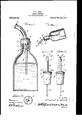
In the accompanying drawings, Figure l,
is a side view of my improved stopper,
showing the same applied to a bottle, the latter being in section and in an upright position. Fig. 2, is a similar View, showlng the bottle in an inclined position for discharging liquid therefrom. Fig. 3, is a front view of the stopper. Fig. 4, is a rea-r View ot the saine. Fig. 5, is a cross sectional view on the 'line of Fig.
et'crring more jnlrticularlyto the drawings, 1 denotes the stopper which may be formed of cork. rubber, or any suitable material, and is adapted to be inserted into the neck of the bottle or retainer in the usual manner. 0n the outer end of the stopper l, is arranged a cap "2 which is formed of any suitable metal is provided With a downwardly projecting annular'tlange which is clenched into engagement .with the upper portion of the stopper to securely fasten the cap thereon. In Jthe cap 2, is arranged a discharge tube 4, the inner end of which is freely dischargedl inserted in the passage formed throughI the stopper and projects a suitable distance into the'passage, as shown. Secured to one side of the tube 4, is a vent tube 5, said vent tube may be secured to the discharge tube in any suitable manner, or may form partof the same. The vent tube isof less diameter than the discharge tube, and the inner end of the vent tube extends entirely through the stop per and projects a suitable distance in the ottle or retainer, as shown. The outer portions of the vent and discharge tubes project a suitable distance be ond the outer side of the cap and are pre erably curved, as shown, to facilitate the pouring of the liquid through the discharge tube. On the upper side of the vent tube, adjacent to its outerend, is formed an upwardly projecting apertured bearing lug 6, to which is pivotally connected a closing plate or disk 7, said plate or disk having a shape corre sponding somewhat'to the out line of the discharge and vent tubes and is slightly larger than the outside dimensions of the ends of the tubes. The plate or disk is provided on its inner side adjacent to its upper end with spaced apertured lugs 8, which engage the lug 6, and through the apertures of said lugs is inserted a pivot pin, whereby the plate or disk 7, is loosely hinged to the vent tube and is adapted toswing freely into and out of engagement with the ends of the tubes when the bottle or container is brought to an upright position or tilted for discharging the liquid therefrom. By means of the closing plate or disk 7, the outer open ends of the vent and discharge tubes will be automatically closed after each discharge of liquid from the container, thus preventing the entrance of dust or insects to the container.
I wish it to be understood that by inserting the discharge tube 4 part Way in the .stopper each time any of the contents of the bottle is removed.
["roln t'he foregoing description, taken in connu-tion with the accompanying 'drawings, the construction and operation of the invention will be readily understood Without requiring a more extended explanation.
ll-aving thus described. my inventioinwhat I claim is:
The combination with a bottle, of a stopp er connected to the neck thereof, and havlng an opening extending through the same7 a fienged cap secured to the stopper having a discharge and vent tube inserted through the same, said vent tube being inserted through the opening of the stopper and into the body ofthe bottle, the discharge tube being inserted part Way into said opening ERNEST LEWS BECK.
Witnesses:
FLORENCE BENNETT, ARNEE E. CAVEN.
Priority Applications (1)
| Application Number | Priority Date | Filing Date | Title |
|---|---|---|---|
| US49861209A US973616A (en) | 1909-05-27 | 1909-05-27 | Bottle-stopper. |
Applications Claiming Priority (1)
| Application Number | Priority Date | Filing Date | Title |
|---|---|---|---|
| US49861209A US973616A (en) | 1909-05-27 | 1909-05-27 | Bottle-stopper. |
Publications (1)
| Publication Number | Publication Date |
|---|---|
| US973616A true US973616A (en) | 1910-10-25 |
Family
ID=3041995
Family Applications (1)
| Application Number | Title | Priority Date | Filing Date |
|---|---|---|---|
| US49861209A Expired - Lifetime US973616A (en) | 1909-05-27 | 1909-05-27 | Bottle-stopper. |
Country Status (1)
| Country | Link |
|---|---|
| US (1) | US973616A (en) |
Cited By (7)
| Publication number | Priority date | Publication date | Assignee | Title |
|---|---|---|---|---|
| US2511429A (en) * | 1948-07-27 | 1950-06-13 | Claremould Plastics Company | Pouring device |
| US2546194A (en) * | 1949-02-21 | 1951-03-27 | Livadas Louis | Pouring stopper for bottles |
| US2639839A (en) * | 1949-10-27 | 1953-05-26 | Sokolik Edward | Regulating pourout for bottles |
| US2753090A (en) * | 1953-06-19 | 1956-07-03 | Charles L Fay | Combination pouring spout and vent for a bottle |
| US3750915A (en) * | 1971-07-19 | 1973-08-07 | P Kearney | Wine pourer and resealer |
| US5961008A (en) * | 1996-11-19 | 1999-10-05 | Peckels; Arganius E. | Method and apparatus for pouring liquid from a bottle |
| WO2017042105A1 (en) | 2015-09-09 | 2017-03-16 | Wsm Bvba | Interconnected flow control mechanism |
-
1909
- 1909-05-27 US US49861209A patent/US973616A/en not_active Expired - Lifetime
Cited By (8)
| Publication number | Priority date | Publication date | Assignee | Title |
|---|---|---|---|---|
| US2511429A (en) * | 1948-07-27 | 1950-06-13 | Claremould Plastics Company | Pouring device |
| US2546194A (en) * | 1949-02-21 | 1951-03-27 | Livadas Louis | Pouring stopper for bottles |
| US2639839A (en) * | 1949-10-27 | 1953-05-26 | Sokolik Edward | Regulating pourout for bottles |
| US2753090A (en) * | 1953-06-19 | 1956-07-03 | Charles L Fay | Combination pouring spout and vent for a bottle |
| US3750915A (en) * | 1971-07-19 | 1973-08-07 | P Kearney | Wine pourer and resealer |
| US5961008A (en) * | 1996-11-19 | 1999-10-05 | Peckels; Arganius E. | Method and apparatus for pouring liquid from a bottle |
| US6123225A (en) * | 1996-11-19 | 2000-09-26 | Peckels; Arganious E. | Method and apparatus for pouring liquid from a bottle |
| WO2017042105A1 (en) | 2015-09-09 | 2017-03-16 | Wsm Bvba | Interconnected flow control mechanism |
Similar Documents
| Publication | Publication Date | Title |
|---|---|---|
| US973616A (en) | Bottle-stopper. | |
| US1151997A (en) | Bottle-stopper. | |
| US961224A (en) | Bottle-opener. | |
| US131748A (en) | Improvement in tops for oil-cams | |
| US848419A (en) | Automatic closure for cans, bottles, &c. | |
| US563667A (en) | Albert s | |
| US621161A (en) | Bottle | |
| US579619A (en) | Stopper for bottles | |
| US573760A (en) | Bottle | |
| US453970A (en) | James thomas ford | |
| US599460A (en) | Stopper and pour-out for bottles | |
| US229749A (en) | Isaac poetbe | |
| US785656A (en) | Bottle. | |
| US225654A (en) | Egbert peaesall smith | |
| US769979A (en) | Non-refillable bottle. | |
| US630564A (en) | Device for closing bottles. | |
| US791136A (en) | Non-refillable bottle. | |
| US580510A (en) | Emma boss | |
| US591619A (en) | George max broemler | |
| US663040A (en) | Bottle-stopper. | |
| US708171A (en) | Non-refillable bottle. | |
| US836782A (en) | Bottle-stopper. | |
| US853097A (en) | Bottle-stopper. | |
| USD22582S (en) | Design for a bottle-stopper | |
| US824447A (en) | Bottle. |