US973350A - Polishing-machine. - Google Patents
Polishing-machine. Download PDFInfo
- Publication number
- US973350A US973350A US54929110A US1910549291A US973350A US 973350 A US973350 A US 973350A US 54929110 A US54929110 A US 54929110A US 1910549291 A US1910549291 A US 1910549291A US 973350 A US973350 A US 973350A
- Authority
- US
- United States
- Prior art keywords
- machine
- polishing
- shells
- pins
- pulleys
- Prior art date
- Legal status (The legal status is an assumption and is not a legal conclusion. Google has not performed a legal analysis and makes no representation as to the accuracy of the status listed.)
- Expired - Lifetime
Links
- 238000005498 polishing Methods 0.000 description 7
- 102100034742 Rotatin Human genes 0.000 description 2
- 101710200213 Rotatin Proteins 0.000 description 2
- 239000002360 explosive Substances 0.000 description 1
- 239000002184 metal Substances 0.000 description 1
Images

Classifications
-
- B—PERFORMING OPERATIONS; TRANSPORTING
- B24—GRINDING; POLISHING
- B24B—MACHINES, DEVICES, OR PROCESSES FOR GRINDING OR POLISHING; DRESSING OR CONDITIONING OF ABRADING SURFACES; FEEDING OF GRINDING, POLISHING, OR LAPPING AGENTS
- B24B5/00—Machines or devices designed for grinding surfaces of revolution on work, including those which also grind adjacent plane surfaces; Accessories therefor
- B24B5/313—Machines or devices designed for grinding surfaces of revolution on work, including those which also grind adjacent plane surfaces; Accessories therefor involving work-supporting means carrying several workpieces to be operated on in succession
- B24B5/32—Machines or devices designed for grinding surfaces of revolution on work, including those which also grind adjacent plane surfaces; Accessories therefor involving work-supporting means carrying several workpieces to be operated on in succession the work-supporting means being indexable
Definitions
- the object of this invention is to provide an improved machine for polishing or buffing cylindrical articles and more especially for butting the metal heads of cartridge shells.
- this object I provide a horizontal table to which a step by step movement of rotation can be imparted and from which stand up a number of'pins on which the articles or shells can be placed.
- the articles are thus carried past butlingwheels or cylinders which are caused to rotate and while the articles are passing the buffing wheels, they also are caused to rotate in the same sense as the wheels.
- a gate or carrier having bufling fingers depending from it is also caused to descend at intervals so that the ends of the articles rotating beneath the fingers may thus be polished.
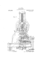
- Fig. 4t is a sec- "tion to a larger scale on the line A-A Fig.
- Fig. 5 is a detail view of the devices for picking the cartridge shell from its supporting pin.
- a locking arm 13 is pivoted beside the table and a tooth 14 on this arm takes into notches 15 in the side of the table. The arm is forced. into.
- the table 12 carries a number of studs on which can turn pins 17 each of which has In order that the table inav be fast upon it a doe ly grooved pulley 18.
- the shells to be bu ed may be placed upon these pins by an operator or may be automatically placed upon them by the n1echanism to be described later.
- a belt pulley 19's belt 20 from which passes over a pulley 21 on a shaft 22 which by bevel gear 23 drives a vertical spindle 24.
- a belt passes from a pulley 26 on the spindle 24. to a ulle 27 on a spindle 28 passing u through a fixed bush 29 on which the ta le 12 turns, the spindle 28 being coaxial with the table see Fig. 4.
- Each of these pinions 31 has fast with it a pulley 3st provided with a driving band 35 of rubber or the like and as the table 12 rotates the pulleys 18, fast with the pins 17 supporting the shells, come into contact with these bands 35 as seen in Figs. 1 and 4 and are thus caused to rotate rap-' idly.
- Such an arm renders the feed 46 are preferably carried by adjustable slides f 52 so that they can be set in toward or away I from the table 12.
- One of the guide pulleys is preferably also adjustable by means of l a handle 53 so that the band l8 may be readily tightened.
- the cartridge shell is non" picked 011' its pin by catches 54 at the month i of a vertical tube 55 shown separately in l Fig. 5 moved through the gate by a lever 56 l pivoted to the gate at 57 and slotted to emi brace a pin 58 on the frame.
- This arm is pulled by a sprin 66 into the position in which it is seen in ig. 1 but is intermittently pushed forward by a cam 67 on the shaft 4.
- a shell comes in front of the'jaws at the end of the arm and when the sprin 66 pulls'the arm back, the shell is brougfit in front of the
- the drawings show the machine fitted I pin 17 on to which it is pressed by a presscr foot 71 carried bv a rod 72 moved u and 55- down by a lever 73 pivoted to the gateat it while its rear end embraces a pin 75 on the frame.
- This automatic feed it is 11" sary to stop the machine should the pick on fail to act. This is effected as inthe specification already referred to by an inspector punch 76 carried by the gate and actuating a rocking lever 77 which actuates the trip lever 78 which can also beactuated by. handle 79.
- What I claim is 1.
- a machine for polishing or bufiing cylindrical articles the' combination of rotating butting wheels, a step by step rotating table carrying the articles'past such wheels, means for simultaneously rotatin the an ticles about their axes andmeans Ior bringing bufling fingers down upon the ends of the articles wh le they are rotating during the stoppages of the table.
Landscapes
- Engineering & Computer Science (AREA)
- Mechanical Engineering (AREA)
- Grinding And Polishing Of Tertiary Curved Surfaces And Surfaces With Complex Shapes (AREA)
- Finish Polishing, Edge Sharpening, And Grinding By Specific Grinding Devices (AREA)
Description
H. D. HODGE.
POLISHING MACHINE.
APPLIGATION mum MAR, 14, 13101 Patented Oct. 18, 1910.
4 SHEETS-SHEETL H, D. HODGE. POLISHING MACHINE.
% F m a APPLICATION nun MAR. 14, 1910 g g fi Patented 0013. 18, 1910.
' 4 SHEETS $3221 2.
H. D. HUDGE.
POLISHING MACHINE.
APPLICATION 31mm MAR.14,1910.
*yg ggg Patented Oct. 18, 1910 45 4 SHEETSSHEET 3 H. D. HODGE. POLISHING MACHINE. APPLICATION FILED MAB-.14, 1910.
Patamsd. Get. 1, we.
wmm
SHEETS SHEET l.
wnwseay.
HDYVA'RD DOUGLAS HODGE, OF W'ALTHAM ABBEY, ENGLAND, ASSIGNOR TO NOBELS EXPLOSIVES COMPANY, LIMITED, GLASGOW, SCOTLAND.
POLISHING-MACHINE.
Specification of Letters E'atent.
Patented Got. 18, 1910.
Application filed March 14, 1910. Serial No. %,291.
Llo all whom it may concern.
Be it known that I, HOWARD -DOUGLAS Hooch, manager of lValtham Factory, Nobels Explosives Co. Ltd, a citizen of the United States, residing at Joyce House, Waltham Abbey, Essex, England, have in vented a new and useful Polishing-Machine, of which the following is a specification.
The object of this invention is to provide an improved machine for polishing or buffing cylindrical articles and more especially for butting the metal heads of cartridge shells. \Vith this object I provide a horizontal table to which a step by step movement of rotation can be imparted and from which stand up a number of'pins on which the articles or shells can be placed. The articles are thus carried past butlingwheels or cylinders which are caused to rotate and while the articles are passing the buffing wheels, they also are caused to rotate in the same sense as the wheels. A gate or carrier having bufling fingers depending from it is also caused to descend at intervals so that the ends of the articles rotating beneath the fingers may thus be polished.
The accompanying drawings show a machine inade in accordance with this inventi n for butting cartridge shells.
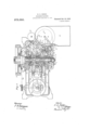
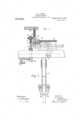
igure tie a plan, Fig. 2 a front View and Fig. 3 a side View. Fig. 4t is a sec- "tion to a larger scale on the line A-A Fig.
1. Fig. 5is a detail view of the devices for picking the cartridge shell from its supporting pin.
1 is the main shaft of the machine driven by a belt pulley 2 and driving by bevel gear 3 avertical shaft at which in turn by bevel gear 5, cross shaft 6 and gear 7 drives a vertical shaft 8 on which is a disk 9 carry ing a wheel 10 which takes into radial slots 11 in the horizontal table l2 which is thus moved step by step in an anti-clockwise direction. locked fast in between the steps, a locking arm 13 is pivoted beside the table and a tooth 14 on this arm takes into notches 15 in the side of the table. The arm is forced. into. engagement by a spring not shown but is moved out of engagement at the proper time by a cam surface 16 on the disk 9 acting upon its nose as is clearly to be seen in The table 12 carries a number of studs on which can turn pins 17 each of which has In order that the table inav be fast upon it a doe ly grooved pulley 18. The shells to be bu ed may be placed upon these pins by an operator or may be automatically placed upon them by the n1echanism to be described later.
On the main. shaft 1 is a belt pulley 19's belt 20 from which passes over a pulley 21 on a shaft 22 which by bevel gear 23 drives a vertical spindle 24. A belt passes from a pulley 26 on the spindle 24. to a ulle 27 on a spindle 28 passing u through a fixed bush 29 on which the ta le 12 turns, the spindle 28 being coaxial with the table see Fig. 4. I
On the'spindle 28 is a spur wheel 30 gearing with aseries of pinions 31 free to turn on studs 32 on a plate carried by the bush 2%). Each of these pinions 31 has fast with it a pulley 3st provided with a driving band 35 of rubber or the like and as the table 12 rotates the pulleys 18, fast with the pins 17 supporting the shells, come into contact with these bands 35 as seen in Figs. 1 and 4 and are thus caused to rotate rap-' idly. While the shells are thus rotatin r on their own axes their ends are buffed by spring fingers 36 carried by the gate 37 which is moved down in guides 38 at the proper times bya cam 39 on the main shaft 1 acting upon a roller 40 carried by the gate. A spring 41 acting on a crosshcad 12 connected by rods 43 to the gate raises the gate when the cam 35) )ermits. In the machine illustrated there are four bufiin r lingers and consequently four driving pu leys 34 but this number may of course be varied if desired. At the same time the cylindrical part of the shell is polished by a series (three in the machine shown) of buiiing wheels H carried on sleeves 45 on pins 46. These sleeves have pulleys 47 fast on them and around these pulleys passes an endless band 48 which also passes over a driving pulley 4-9 on the spindle 24 and over guide pulleys 50 as clearly seen in Figs. 1 and 3. The result of this arrangement is that the butting wheels are rapidly rotated in the same direction as are the shells which are thus efiicicntly polished; In order-that the machine may be adapted tobufl'. shells in 1 which the metallic part is of varying length, bufling wheels of varying depth are provided and the wheels required are clamped upon the sleeves 45 by nuts 51 working on screw threads cut on the sleeves. lhe pins segment 63. Such an arm renders the feed 46 are preferably carried by adjustable slides f 52 so that they can be set in toward or away I from the table 12. One of the guide pulleys is preferably also adjustable by means of l a handle 53 so that the band l8 may be readily tightened. The cartridge shell is non" picked 011' its pin by catches 54 at the month i of a vertical tube 55 shown separately in l Fig. 5 moved through the gate by a lever 56 l pivoted to the gate at 57 and slotted to emi brace a pin 58 on the frame. As the gate descends the tube descends with it and also moves through it,owing to the rocking of l the lever about'thepin 58 the sum of these movements being as clent to enable thel catches to pass beneath the rim of the curtridge head. As the gate rises the shell is picked oii' its pin and on the next descent I of thegate is pushed up into the tube by l the succeeding shell and is eventually led by a flexible tube from the top of the tube g to a convenient receptacle.
with means for automatically putting the shells on to the pins 17. Such means, together with the pick off and trip mechanism for stopping the machine should the pick off l fail to act are precisely similar to the correspending parts most fully described in the specification No. 937,604, The main featuresare as follows 59 is .a table on which the shells are placed head downward and from which they slide on to a rotating table I 60 which carries them to a guideway 61 at the'mouth of which is an agitating wheel 62. The shells arrive at the end of this guideway in single file and present themselves before a segment 63. In order to give a definite feed of the shells one by one an" arm 64 is pivoted at 65 just above the table. This arm is pulled by a sprin 66 into the position in which it is seen in ig. 1 but is intermittently pushed forward by a cam 67 on the shaft 4. As it moves forward a shell comes in front of the'jaws at the end of the arm and when the sprin 66 pulls'the arm back, the shell is brougfit in front of the The drawings show the machine fitted I pin 17 on to which it is pressed by a presscr foot 71 carried bv a rod 72 moved u and 55- down by a lever 73 pivoted to the gateat it while its rear end embraces a pin 75 on the frame. With this automatic feed it is 11" sary to stop the machine should the pick on fail to act. This is effected as inthe specification already referred to by an inspector punch 76 carried by the gate and actuating a rocking lever 77 which actuates the trip lever 78 which can also beactuated by. handle 79.
What I claim is 1. In a machine for polishing or bufiing cylindrical articles, the' combination of rotating butting wheels, a step by step rotating table carrying the articles'past such wheels, means for simultaneously rotatin the an ticles about their axes andmeans Ior bringing bufling fingers down upon the ends of the articles wh le they are rotating during the stoppages of the table.
2. In a machine for polishing or butting cylindrical articles, the combination of retating butfing Wheels, 21 step by step rotating table, pins carried" thereby, pulleys on the pins, driving pulleys adapted to engage and rotate the pulleys on the, ins and means for rotatinu such driving pu lleys.
3. In a machine for polishing or bufi'ing cylindrical articles, the combination of rotating bufiing wheels, a step table, pins carried thereby pulleys on the rotate the pulleys'on'the pins, means or rotating such driving pulleys, and means for bringing bufiing fingersdown,unon the ends 90 of the articles while they; are rotating.
HOWARD DOUGLAS HODG-F Witnesses:
GEORGE SMITH, Jesse A. SOUTH.
by step rotating
Priority Applications (1)
| Application Number | Priority Date | Filing Date | Title |
|---|---|---|---|
| US54929110A US973350A (en) | 1910-03-14 | 1910-03-14 | Polishing-machine. |
Applications Claiming Priority (1)
| Application Number | Priority Date | Filing Date | Title |
|---|---|---|---|
| US54929110A US973350A (en) | 1910-03-14 | 1910-03-14 | Polishing-machine. |
Publications (1)
| Publication Number | Publication Date |
|---|---|
| US973350A true US973350A (en) | 1910-10-18 |
Family
ID=3041729
Family Applications (1)
| Application Number | Title | Priority Date | Filing Date |
|---|---|---|---|
| US54929110A Expired - Lifetime US973350A (en) | 1910-03-14 | 1910-03-14 | Polishing-machine. |
Country Status (1)
| Country | Link |
|---|---|
| US (1) | US973350A (en) |
-
1910
- 1910-03-14 US US54929110A patent/US973350A/en not_active Expired - Lifetime
Similar Documents
| Publication | Publication Date | Title |
|---|---|---|
| US1761189A (en) | Machine for applying flexible casings to magazines | |
| US1921485A (en) | Feeder for portable tools | |
| US1287334A (en) | Signature-gatherer. | |
| US1908771A (en) | Automatically operating discharge device for cigarette machines | |
| US1799332A (en) | Apparatus for cleaning or polishing articles | |
| US2390691A (en) | Measuring device | |
| US1085888A (en) | Pamphlet-coverer. | |
| US1602680A (en) | Automatic cylindrical grinding machine | |
| US2625961A (en) | Wire netting machine | |
| US2693843A (en) | Apparatus for automatically assembling a structure consisting of a number of separate parts | |
| US1409208A (en) | Grinding machine | |
| US2341292A (en) | Gauging machine | |
| US1340219A (en) | Slicing-machine | |
| US1449599A (en) | Machine for use in connection with the manufacture of corks and the like | |
| US1402700A (en) | A cobpobatiokt of | |
| US2406562A (en) | Trimming machine | |
| US1332279A (en) | Bottle-capping machine | |
| US1754140A (en) | Grinding or abrading machine | |
| US927036A (en) | Buffing-machine. | |
| US1653641A (en) | Feeding machine | |
| US937608A (en) | Apparatus for weaving veneer strips. | |
| US1926577A (en) | Machine for grinding the ends of cotton gin ribs | |
| US1161242A (en) | Worm-thread-grinding machine. | |
| US1255693A (en) | Machine for pointing carbons. | |
| US870895A (en) | Box-filling machine. |