US9732780B2 - Cantilever assembly - Google Patents
Cantilever assembly Download PDFInfo
- Publication number
- US9732780B2 US9732780B2 US14/618,383 US201514618383A US9732780B2 US 9732780 B2 US9732780 B2 US 9732780B2 US 201514618383 A US201514618383 A US 201514618383A US 9732780 B2 US9732780 B2 US 9732780B2
- Authority
- US
- United States
- Prior art keywords
- bolt
- slot
- cantilever
- spaced apart
- side walls
- Prior art date
- Legal status (The legal status is an assumption and is not a legal conclusion. Google has not performed a legal analysis and makes no representation as to the accuracy of the status listed.)
- Active
Links
- 239000012212 insulator Substances 0.000 description 10
- 230000003137 locomotive effect Effects 0.000 description 3
- 239000000463 material Substances 0.000 description 3
- 229910000831 Steel Inorganic materials 0.000 description 2
- XAGFODPZIPBFFR-UHFFFAOYSA-N aluminium Chemical compound [Al] XAGFODPZIPBFFR-UHFFFAOYSA-N 0.000 description 2
- 229910052782 aluminium Inorganic materials 0.000 description 2
- 230000000712 assembly Effects 0.000 description 2
- 238000000429 assembly Methods 0.000 description 2
- 238000010276 construction Methods 0.000 description 2
- 238000003780 insertion Methods 0.000 description 2
- 230000037431 insertion Effects 0.000 description 2
- 238000009434 installation Methods 0.000 description 2
- 230000000717 retained effect Effects 0.000 description 2
- 239000010959 steel Substances 0.000 description 2
- ATJFFYVFTNAWJD-UHFFFAOYSA-N Tin Chemical compound [Sn] ATJFFYVFTNAWJD-UHFFFAOYSA-N 0.000 description 1
- 239000002131 composite material Substances 0.000 description 1
- 238000004519 manufacturing process Methods 0.000 description 1
- 238000012986 modification Methods 0.000 description 1
- 230000004048 modification Effects 0.000 description 1
- 239000004033 plastic Substances 0.000 description 1
- 229920003023 plastic Polymers 0.000 description 1
Images


Classifications
-
- F—MECHANICAL ENGINEERING; LIGHTING; HEATING; WEAPONS; BLASTING
- F16—ENGINEERING ELEMENTS AND UNITS; GENERAL MEASURES FOR PRODUCING AND MAINTAINING EFFECTIVE FUNCTIONING OF MACHINES OR INSTALLATIONS; THERMAL INSULATION IN GENERAL
- F16B—DEVICES FOR FASTENING OR SECURING CONSTRUCTIONAL ELEMENTS OR MACHINE PARTS TOGETHER, e.g. NAILS, BOLTS, CIRCLIPS, CLAMPS, CLIPS OR WEDGES; JOINTS OR JOINTING
- F16B7/00—Connections of rods or tubes, e.g. of non-circular section, mutually, including resilient connections
- F16B7/18—Connections of rods or tubes, e.g. of non-circular section, mutually, including resilient connections using screw-thread elements
- F16B7/187—Connections of rods or tubes, e.g. of non-circular section, mutually, including resilient connections using screw-thread elements with sliding nuts or other additional connecting members for joining profiles provided with grooves or channels
-
- B—PERFORMING OPERATIONS; TRANSPORTING
- B60—VEHICLES IN GENERAL
- B60M—POWER SUPPLY LINES, AND DEVICES ALONG RAILS, FOR ELECTRICALLY- PROPELLED VEHICLES
- B60M1/00—Power supply lines for contact with collector on vehicle
- B60M1/12—Trolley lines; Accessories therefor
- B60M1/20—Arrangements for supporting or suspending trolley wires, e.g. from buildings
- B60M1/24—Clamps; Splicers; Anchor tips
Definitions
- the present invention relates to overhead contact systems in the transit traction power industry and, more particularly, to a cantilever assembly for such systems.
- Electrified train transit systems are popular in urban settings due to their low level of pollution and high efficiency and reliability.
- Such transit systems typically feature an electric locomotive that pulls train cars for carrying passengers and that receives power from an overhead contact system.
- Overhead contact systems typically feature messenger and contact wires that are suspended over the track that the electric train cars travel on. The top of the electric locomotive is provided with a pantograph which contacts the contact wire so that the locomotive receives power.
- the messenger and contact wires are typically suspended by a cantilever assembly, such as the one indicated in general at 8 in FIG. 1 .
- the cantilever assembly includes two or more insulated, rigid cantilever arms, illustrated at 10 and 12 , that are attached by their proximal ends via members 14 and 16 to a pole 18 positioned next to the tracks.
- the distal end of the lower cantilever arm 12 which features a tilted orientation, is typically attached to the underside of the upper cantilever arm 10 , which is positioned in a generally horizontal orientation.
- the lower cantilever arm provides support for the upper cantilever arm.
- a messenger saddle 20 is typically positioned at the distal end of the upper cantilever arm.
- a steady arm 21 is typically attached by its proximal end to the lower cantilever arm, and an insulated swivel clamp 22 for the contact wire is typically positioned at the distal end of the steady arm.
- the messenger passes over the saddle 20 and its ends are connected to the contact wire by hangers to form a bridal assembly where the contact wire is suspended by both the swivel clamp 22 and the messenger cable.
- the cantilever assembly which includes the upper and lower cantilever arms and the steady arm, are critical components for securing and maintaining contact and messenger wire heights and locations in an overhead contact system.
- Steel pipe is typically used for the upper and lower cantilever arms and the steady arm. This makes the components heavy and difficult to handle and install. A need therefore exists for a cantilever and steady arms that provide a reduction in weight.
- the cantilever assembly must be properly configured for optimal performance.
- a large number of cantilever assemblies must be assembled and installed for an overhead contact system.
- prior art cantilever assemblies typically use clevis pipe clamps 24 and 26 to secure the distal end of the lower cantilever arm to the underside of the upper cantilever arm and to secure the proximal end of the steady arm to the lower cantilever arm.
- Such clamps feature a number of different parts that are difficult to handle during installation and may become easily separated and lost.
- assembly and tightening of the clamps is time consuming.
- a need therefore also exists for a fastening bracket for the cantilever and steady arms of a cantilever assembly that is quick and easy to install and that remains as a single assembly during installation.
- FIG. 1 is a side elevational view of a prior art cantilever assembly
- FIG. 2 is a perspective view of an embodiment of the cantilever assembly of the invention
- FIG. 3 is an exploded view of an embodiment of an attachment bracket of the cantilever assembly of FIG. 2 ;
- FIGS. 4 is an assembled view of the attachment bracket of FIG. 3 being installed on the lower cantilever arm of FIG. 2 ;
- FIG. 5 is an assembled view of the attachment bracket of FIG. 3 installed on the lower cantilever arm of FIG. 2 ;
- FIG. 6 is an enlarged partial end elevational view of the attachment bracket and lower cantilever arm of FIG. 5 ;
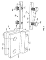
- FIG. 7 is an enlarged perspective view of the distal ends of the upper and lower cantilever arms with the attachment brackets and other components installed;
- FIG. 8 is an exploded view of an embodiment of an end cap assembly
- FIG. 9 is an enlarged end perspective view of the end cap assembly of FIG. 8 ;
- FIG. 10 is a side perspective view of the end cap assembly of FIG. 9 being installed on a cantilever arm;
- FIG. 11 is a partial side perspective view of the end cap assembly of FIGS. 8-10 installed on an insulator.
- the assembly includes an upper cantilever arm 32 , a lower cantilever arm 34 and a steady arm 36 .
- the upper and lower cantilever arms 32 and 34 and the steady arm 36 are each preferably extruded from aluminum.
- the steady arm preferably includes an inverted U-shaped cross section to provide weight and material savings while providing rigidity. Alternative materials, such as plastics or composites, and manufacturing methods may alternatively be used for each component.
- the three components are secured together with attachment brackets 42 , 44 and 45 , as described in greater detail below. Attachment brackets 42 , 44 and 45 are also preferably extruded from aluminum.
- a messenger saddle 46 is positioned on the distal end of the upper cantilever arm 32 , while a contact wire swivel clamp 48 is attached to the distal end of the steady arm 36 .
- the outside diameter of the upper and lower cantilever arms 32 and 34 preferably matches that of a steel pipe (typically 2.375 inches). This allows the attachment of hardware already designed for a nominal 2 inch pipe.
- attachment bracket 45 An enlarged view of attachment bracket 45 is provided in FIG. 3 .
- the attachment bracket features a generally H-shaped cross section with a pair of top fins 64 a and 64 b and downwardly extending leg portions 54 a and 54 b .
- the inner surfaces of leg portions 54 a and 54 b define a generally U-shaped seat 57 .
- a pair of openings 62 a and 62 b are provided in each fin connector portion 64 a and 64 b .
- apertures 66 a and 66 b are provided in the leg portions 54 a and 54 b .
- the number of openings and apertures shown are examples only and the fin and leg portions of the attachment bracket may be provided with more or less openings and apertures as is suitable for the application.
- a single fin may be substituted for the pair of top fins 64 a and 64 b , or an alternative number of top fins may otherwise be used.
- a pair of nut plates indicated in general at 74 a and 74 b in FIG. 3 , feature threaded bores 76 a and 76 b that receive bolts, such as those indicated in general at 86 a and 86 b . More specifically, as illustrated for bolt 86 a , each bolt features a threaded shaft 88 a and a head 92 a , with the threaded shaft received within a corresponding nut plate threaded bore 76 a . The distal end of each bolt threaded shaft optionally features a cup point, as illustrated at 77 b for bolt 86 b .
- each nut plate also features a top surface 78 a , an outer surface 80 a , a bottom surface 84 a and, as illustrated for nut plate 74 b , an inner surface 82 b.
- each leg portion 54 a and 54 b pass through corresponding apertures 66 a ( FIGS. 4 ) and 66 b ( FIG. 5 ) of leg portions 54 a and 54 b of the attachment bracket.
- the threaded shafts (such as 88 a and 88 b ) of the bolts have diameters that are sized smaller than the diameters of the corresponding apertures (such as 66 a and 66 b ) so that the threads of the bolts do not engage the apertures (which are not threaded) as the bolts pass there through.
- the bolts, assembled through the apertures of the attachment bracket leg portions, are initially unscrewed with respect to the nut plates so that the cup points (on the distal ends of the bolt threaded shafts) are generally flush with, or recessed with respect to, the inner surfaces of the nut plates so as not to protrude radially inward therefrom.
- An example of this is shown in FIG.
- the nut plates 74 a and 74 b are then slid into channels 102 a and 102 b of cantilever arm 34 so that the cantilever arm is positioned within the U-shaped seat ( 57 in FIG. 3 ) of the attachment bracket.
- the nut plates 74 a and 74 b each feature tapered ends to facilitate their insertion into the channels 102 a and 102 b of the cantilever arm.
- lower cantilever arm 34 features a central pipe portion 98 that defines central cylindrical bore 100 and that is flanked by the longitudinal fastening channels 102 a and 102 b .
- fastening channel 102 b features side opening slots bordered by lower wall 103 b and upper wall 105 b .
- Fastening channel 102 a is similarly configured.
- the cantilever arm 34 also preferably includes generally square ducts 104 , 106 and generally triangular ducts 108 , 110 , 112 and 114 that run parallel to central bore 100 and fastening channels 102 a and 102 b .
- Central bore 100 is preferably threaded so that components such as insulator 116 ( FIG. 2 ) may be attached to the cantilever arm.
- Upper cantilever arm 32 ( FIG. 2 ) features the same construction as lower cantilever arm 34 .
- Alternative embodiments of the upper and lower cantilever arms may optionally eliminate, or vary the shape of, some or all of the square and triangular ducts, as well as the central bore.
- all the ducts may be generally circular in shape.
- alternative embodiments of the cantilever arms may feature an overall cross section that is a shape other than round (such as octagonal, square, triangular, etc.). Of course the shape of the leg portions and seat of the attachment bracket would have to be changed accordingly.
- the dimensions of the seat 57 of the attachment bracket correspond to the diameter and positions of the slots of the cantilever arm so that the slots align with the apertures 66 a and 66 b of the leg portions 54 a and 54 b of the attachment bracket when the cantilever arm is positioned within the seat 57 .
- the bolts of the attachment bracket may be turned to lock the attachment bracket in the selected position on the lower cantilever arm. As the bolts are turned, they force the nut plates outward to press against the cantilever arm, securing the assembly in place. More specifically, as illustrated for bolt 86 a in FIG.
- bolt head 92 b is turned with a tool so that the outer surface of the nut plate 74 b engages the inner surfaces of lower and upper walls 103 b and 105 b of the cantilever arm 34 , as illustrated by arrows 120 and 122 .
- the distal end of the threaded shaft 88 b which optionally features the cup point ( 77 b of FIG. 3 ), presses or “bites” into the outer surface of the central pipe portion 98 of the cantilever arm, as illustrated by arrow 118 .
- the nut plates 74 a and 74 b are secured or retained within the channels 102 a and 102 b of the cantilever arm 34 and the attachment bracket is secured to the cantilever arm.
- a lock or jam nut 124 b may optionally be provided on the threaded shaft 88 b of each bolt so as to be positioned between the head 92 b of the bolt and a corresponding leg portion ( 54 b for bolt 86 b ). After each bolt is tightened as described above, the corresponding lock or jam nut 124 b is tightened so as to engage the outer surface of the leg portion ( 54 b for bolt 86 b ) of the attachment bracket to lock the bolt in the engaged configuration.
- the attachment bracket 45 is quickly and securely fastened to the lower cantilever arm 34 .
- the lower fin 152 of the attachment bracket 44 engaging the upper cantilever arm 32 is received in the space 65 ( FIG. 3 ) between the upper fins 64 a and 64 b of the attachment bracket 45 secured to the lower cantilever arm 34 and is held in place by a pin, bolt or other fastener 126 passing through the opposing pair of openings in upper fins 64 a and 64 b and a corresponding opening formed in lower fin 152 .
- the steady arm 36 is attached at its proximal end 140 by a connector 142 to the fin 52 of the attachment bracket 42 .
- the connector 142 is secured to the tin by a bolt or other fastener 144 that passes through opening (not shown) of the fin 52 .
- the proximal ends 146 and 148 of insulators 116 and 151 are adapted to be mounted to a support such as a wall or pole (not shown), such as in the manner illustrated in FIG. 1 .
- the insulators may be excluded so that the proximal ends of the upper and lower cantilever arms 32 and 34 are instead attached to the pole or wall.
- a messenger seat 46 is attached to the distal end of the upper cantilever arm. This preferably is accomplished by a bracket 164 that also engages a fastening channel of the upper cantilever arm.
- an end cap or cup is indicated in general at 200 .
- the end cup may be used to attach an insulator (such as 151 or 116 of FIG. 2 ) to a cantilever arm.
- the cup may be used in other ways as well.
- the cup features a generally cylindrical body 201 that defines an interior space 202 and is provided with opposing side openings 218 a and 218 b . Each opening is preferably surrounded by a flattened portion 204 a and 204 b to facilitate engagement of the heads 208 a and 208 b of bolts 206 a and 206 b with a wrench or other tool.
- the bolts feature threaded shafts 210 a and 210 b that are sized to pass though the openings 218 a and 218 b (which are not threaded).
- the threaded shafts of the bolts engage threaded openings 214 a and 214 b of nut plates 212 a and 212 b , which feature a construction similar to the nut plates 74 a and 74 b described above with respect to FIGS. 3-7 .
- the distal end of the threaded shaft of each bolt may optionally be provided with a cup point 216 a.
- the closed end of the end cup is secured to an insulator 151 via a bolt or other fastener passing through an opening in the closed end of the end cup.
- Alternative fastening arrangements known in the art may be used to attach the end cup to the insulator. As explained below, this provides quick assembly of the insulator to cantilever arm.
- the bolts 206 a and 206 b are initially unscrewed (via heads 208 a and 208 b ) with respect to the nut plates 212 a and 212 b so that the optional cup points 216 are flush with, or recessed with respect to, the inner surfaces of the nut plates 212 a and 212 b .
- This is shown in FIG. 8 but with the bolts 206 a and 206 b not positioned through the openings 218 a and 218 b of the cup body for ease of illustration.
- the bolts 206 a and 206 b are placed in the positions illustrated in FIG. 8 after they are passed through the openings 218 a and 218 b of the cup body and then attached to the nut plates 212 a and 212 b , as illustrated in FIGS. 9-11 .
- the nut plates 212 a and 212 b are then slid into channels 240 a and 240 b of cantilever arm 232 so that the end portion of the cantilever arm is may be received within the interior space 202 of the cup body.
- the nut plates 212 a and 212 b each feature tapered ends to facilitate their insertion into the channels 240 a and 240 b of the cantilever arm.
- the heads 208 a and 208 b of bolts 206 a and 206 b are turned using a tool to force the nut plates outward to press against the cantilever arm, securing the assembly in place. More specifically, the outer surfaces of the nut plates engage the inner surfaces of lower and upper walls that define the slots of the cantilever arm, in the manner illustrated in FIG. 6 for attachment bracket 45 while the optional cup points (such as 216 a of FIG.
- the cantilever arm 232 ( FIG. 10 ) is identical to the cantilever arm 332 ( FIG. 11 ) with the exception of the shapes of the internal ducts.
- the cantilever arms 232 , 332 may be used interchangeably with the end cup 200 .
- the above embodiment of the present invention therefore provides a lightweight but rugged and durable structure whereby the components are quickly and securely fastened together.
- the above embodiment also allows for quick adjustment of the cantilever assembly and allows other components to be quickly, easily and securely attached to the upper and/or the lower cantilever arms.
Landscapes
- Engineering & Computer Science (AREA)
- Mechanical Engineering (AREA)
- General Engineering & Computer Science (AREA)
- Clamps And Clips (AREA)
- Mutual Connection Of Rods And Tubes (AREA)
Abstract
Description
Claims (15)
Priority Applications (2)
| Application Number | Priority Date | Filing Date | Title |
|---|---|---|---|
| US14/618,383 US9732780B2 (en) | 2014-12-19 | 2015-02-10 | Cantilever assembly |
| CA2915482A CA2915482C (en) | 2014-12-19 | 2015-12-16 | Cantilever assembly |
Applications Claiming Priority (2)
| Application Number | Priority Date | Filing Date | Title |
|---|---|---|---|
| US201462094343P | 2014-12-19 | 2014-12-19 | |
| US14/618,383 US9732780B2 (en) | 2014-12-19 | 2015-02-10 | Cantilever assembly |
Publications (2)
| Publication Number | Publication Date |
|---|---|
| US20160177993A1 US20160177993A1 (en) | 2016-06-23 |
| US9732780B2 true US9732780B2 (en) | 2017-08-15 |
Family
ID=56128912
Family Applications (1)
| Application Number | Title | Priority Date | Filing Date |
|---|---|---|---|
| US14/618,383 Active US9732780B2 (en) | 2014-12-19 | 2015-02-10 | Cantilever assembly |
Country Status (2)
| Country | Link |
|---|---|
| US (1) | US9732780B2 (en) |
| CA (1) | CA2915482C (en) |
Cited By (6)
| Publication number | Priority date | Publication date | Assignee | Title |
|---|---|---|---|---|
| US20190106015A1 (en) * | 2017-10-06 | 2019-04-11 | Afl Telecommunications Llc | Strut insulators |
| CN110932167A (en) * | 2019-11-01 | 2020-03-27 | 成都云铁智能交通科技有限公司 | Contact net and power supply unit ground monitoring devices |
| US10925178B2 (en) * | 2019-04-04 | 2021-02-16 | Bell Helicopter Textron Inc. | Avionic sliding rack |
| US11198455B2 (en) * | 2017-10-31 | 2021-12-14 | Kawasaki Jukogyo Kabushiki Kaisha | Connecting hanger bolt and connecting hanger bolt installation mechanism |
| US20220128189A1 (en) * | 2021-11-16 | 2022-04-28 | Dongguan Ortur Intelligent Technologies Co., Ltd. | Laser module lifting apparatus with protecting function |
| US11708173B2 (en) | 2019-08-08 | 2023-07-25 | Textron Innovations Inc. | Avionic sliding rack |
Families Citing this family (8)
| Publication number | Priority date | Publication date | Assignee | Title |
|---|---|---|---|---|
| US10455824B2 (en) * | 2014-11-03 | 2019-10-29 | Rick Eugene LAWRENCE | Agricultural crop application system |
| US9732780B2 (en) * | 2014-12-19 | 2017-08-15 | Impulse Nc Llc | Cantilever assembly |
| CN106740276B (en) * | 2016-12-30 | 2023-07-14 | 中国国家铁路集团有限公司 | A positioning column for an oblique arm |
| US11324213B2 (en) | 2019-03-07 | 2022-05-10 | Hagie Manufacturing Company | Drop-down applicators for an agricultural sprayer |
| US10517786B1 (en) * | 2019-07-17 | 2019-12-31 | David Lue | Dental chair armrest |
| CN112525170B (en) * | 2020-10-28 | 2022-06-21 | 中铁大桥局集团第五工程有限公司 | Suspension bridge cable saddle accurate positioning method based on APP system |
| GB2600772B (en) * | 2020-11-10 | 2023-04-19 | Hastec Rail Ltd | Improved registration arm |
| PL73588Y1 (en) * | 2022-11-29 | 2024-09-23 | Mabo Spółka Z Ograniczoną Odpowiedzialnością | Suspension of the overhead contact line |
Citations (55)
| Publication number | Priority date | Publication date | Assignee | Title |
|---|---|---|---|---|
| US446546A (en) | 1891-02-17 | Electric eailway signal | ||
| US1076630A (en) | 1904-10-19 | 1913-10-21 | Westinghouse Electric & Mfg Co | Supporting structure for trolley-conductors. |
| US2700705A (en) | 1949-09-27 | 1955-01-25 | Cleveland Crane Eng | Electrical duct and trolley collector |
| GB800575A (en) | 1955-07-18 | 1958-08-27 | British Insulated Callenders | Improvements in supporting overhead conductors for electric railways |
| GB835227A (en) | 1955-06-28 | 1960-05-18 | British Insulated Callenders | Improvements in or relating to overhead electric traction systems |
| GB904944A (en) | 1958-08-06 | 1962-09-05 | British Insulated Callenders | Improvements in or relating to section insulators for use in overhead conductors of electric traction systems |
| GB933972A (en) | 1961-01-25 | 1963-08-14 | British Insulated Callenders | Improvements in or relating to cantilever structures for overhead electric traction systems |
| US3222464A (en) | 1963-10-04 | 1965-12-07 | Cleveland Crane Eng | Trolley conductor |
| US3462110A (en) | 1967-06-26 | 1969-08-19 | Bliss Co | Support assembly |
| US3644688A (en) | 1969-01-15 | 1972-02-22 | British Railways Board | Overhead electric supply systems for vehicles |
| US3975580A (en) * | 1975-05-08 | 1976-08-17 | A. B. Chance Company | Articulated crossarm assembly for electrical conductor support structure |
| US4163537A (en) | 1976-07-12 | 1979-08-07 | Societe Anonyme Des Ateliers Marcadet Mobilier | Bearer structure for assembling modular elements |
| JPS5679031A (en) | 1979-11-30 | 1981-06-29 | Japanese National Railways<Jnr> | Oil feeder of oil feeding apparatus for trolley wire |
| DE3207238A1 (en) | 1982-02-25 | 1983-09-01 | Licentia Patent-Verwaltungs-Gmbh, 6000 Frankfurt | Damped steady arm |
| US4496061A (en) | 1980-10-09 | 1985-01-29 | Unarco Industries, Inc. | Connector means for securing slotted members |
| US4523054A (en) * | 1983-04-04 | 1985-06-11 | Interpace Corporation | Line-past insulator support system, method of assembly thereof, and clamp for use therein |
| US4679672A (en) | 1985-01-30 | 1987-07-14 | Bicc Public Limited Company | Overhead electric traction system for railways |
| US4941763A (en) | 1987-10-22 | 1990-07-17 | Mps Industries, Inc. | Grooved support column having adaptable connectors |
| US5192145A (en) * | 1990-05-21 | 1993-03-09 | Wolfgang Rixen | Cross coupling for bars |
| RU2021919C1 (en) | 1992-02-03 | 1994-10-30 | Василий Андреевич Брюзгин | Device for coupling registration and steady arms of contact system |
| US5380961A (en) | 1989-12-20 | 1995-01-10 | Oy Sekko Ab | Device for connecting the contact cable for vehicles running on rails |
| US5634300A (en) | 1994-03-10 | 1997-06-03 | Plascore Inc. | Wall system employing grooved posts, connector blocks and T-bolt receiving battens |
| US5657842A (en) | 1995-07-10 | 1997-08-19 | Deutsche Forschungsanstalt Fur Luft Und Raumfahrt B.V. | Brush contact for a vehicle |
| US5746535A (en) * | 1995-06-08 | 1998-05-05 | Heron Sondermaschinen Und Steuerungen Ges.M.B.H | Plate fastener |
| US5772158A (en) | 1996-12-02 | 1998-06-30 | Blanding; Douglas | Apparatus for laterally offsetting power lines from utility poles |
| US5881851A (en) | 1996-07-26 | 1999-03-16 | Alstom Transport Electrification | Suspension for an overhead electrification plant for railway lines or similar |
| JPH1181487A (en) | 1997-09-03 | 1999-03-26 | Otis Elevator Co | T bolt support and its installation method |
| US5979119A (en) | 1996-03-27 | 1999-11-09 | Trafton; Ronald H. | Components and assemblies for building construction and methods of making and using same |
| WO2000013929A1 (en) | 1998-09-09 | 2000-03-16 | Siemens Aktiengesellschaft | Hinged cantilever for catenary-type overhead line systems |
| US6185887B1 (en) | 1996-04-29 | 2001-02-13 | Syma Intercontinental Ag | Shaped bar and clamping section for a shaped bar |
| US6347592B1 (en) | 1998-01-13 | 2002-02-19 | Roy E. Gessert | Modular workbench and kit therefor |
| US6349912B1 (en) | 1999-03-27 | 2002-02-26 | De-Sta-Co Metallerzeugnisse Gmbh | Supporting structure |
| JP2003080977A (en) | 2001-09-11 | 2003-03-19 | East Japan Railway Co | Trolley wire detent bracket |
| US6565279B1 (en) * | 2002-01-14 | 2003-05-20 | Kiefer Pool Equipment Co. | Clamp for pipes or for other cylindrical struts |
| US6584918B2 (en) * | 2000-12-19 | 2003-07-01 | Project Systems Furniture Co., Ltd. | Desk with a leg-and-stretcher coupling unit |
| US20040036389A1 (en) * | 2002-08-21 | 2004-02-26 | Chiang-Hai Tsai | Extruded aluminum computer case structure with connecting sheets |
| US6712543B1 (en) * | 1999-07-21 | 2004-03-30 | Fms Forder-Und Montage-Systeme Schmalzhofer Gmbh | Connecting device for profiled bars with grooves |
| JP2004276882A (en) | 2003-03-19 | 2004-10-07 | Railway Technical Res Inst | Trolley wire curving device |
| US7090174B2 (en) | 2001-11-09 | 2006-08-15 | Andrew Corporation | Anchor rail adapter and hanger and method |
| US20060180702A1 (en) * | 2004-11-08 | 2006-08-17 | Pfeifer Thomas A | Tubular interconnecting support structure |
| US7159262B2 (en) | 2003-10-07 | 2007-01-09 | Jackson George W | Bridge overhang bracket |
| US20070277445A1 (en) | 2004-09-10 | 2007-12-06 | Andrew Michell | Locking Mechanism for Use With Staging System |
| US7389621B2 (en) | 2004-02-11 | 2008-06-24 | International Property Rights Ltd. | Rapidly deployable temporary modular structures and component elements thereof |
| US7441311B2 (en) | 2005-03-04 | 2008-10-28 | Breeze-Torca Products, Llc | T-bolt clamp quick attach latch |
| US20090064626A1 (en) | 2007-09-11 | 2009-03-12 | You Bai Sen | Channel Anchoring Device For The Construction Industry |
| CN201272254Y (en) | 2008-07-24 | 2009-07-15 | 义马煤业(集团)有限责任公司 | Overhead line electric locomotive pantograph |
| US7654057B2 (en) | 2005-08-08 | 2010-02-02 | Sergio Zambelli | Anchoring insert for embedding in a concrete component and concrete component provided therewith |
| US7748420B2 (en) | 2006-11-24 | 2010-07-06 | Steven Palmer Young | Dadoing system |
| US20100226732A1 (en) | 2009-03-03 | 2010-09-09 | Hilti Aktiengesellschaft | Self-tapping screw |
| WO2010136955A2 (en) | 2009-05-25 | 2010-12-02 | Satferr S.R.L. | Cantilever for supporting live cables of railway, trolley and subway lines |
| US7931420B2 (en) * | 2004-12-01 | 2011-04-26 | Gimatic S.P.A | Multivalent section for making frames, supports, supporting structures and the like |
| US8100600B2 (en) * | 2008-10-23 | 2012-01-24 | Robert Bosch Gmbh | Pivoting connector assembly for connecting two members |
| US20120175479A1 (en) * | 2011-01-07 | 2012-07-12 | Gary Graham | Cantilever assembly |
| US8888056B2 (en) | 2012-05-21 | 2014-11-18 | Syncmold Enterprise Corp. | Detachable lifting module |
| US20160177993A1 (en) * | 2014-12-19 | 2016-06-23 | Impulse Nc Llc | Cantilever assembly |
-
2015
- 2015-02-10 US US14/618,383 patent/US9732780B2/en active Active
- 2015-12-16 CA CA2915482A patent/CA2915482C/en active Active
Patent Citations (58)
| Publication number | Priority date | Publication date | Assignee | Title |
|---|---|---|---|---|
| US446546A (en) | 1891-02-17 | Electric eailway signal | ||
| US1076630A (en) | 1904-10-19 | 1913-10-21 | Westinghouse Electric & Mfg Co | Supporting structure for trolley-conductors. |
| US2700705A (en) | 1949-09-27 | 1955-01-25 | Cleveland Crane Eng | Electrical duct and trolley collector |
| GB835227A (en) | 1955-06-28 | 1960-05-18 | British Insulated Callenders | Improvements in or relating to overhead electric traction systems |
| GB800575A (en) | 1955-07-18 | 1958-08-27 | British Insulated Callenders | Improvements in supporting overhead conductors for electric railways |
| GB904944A (en) | 1958-08-06 | 1962-09-05 | British Insulated Callenders | Improvements in or relating to section insulators for use in overhead conductors of electric traction systems |
| GB933972A (en) | 1961-01-25 | 1963-08-14 | British Insulated Callenders | Improvements in or relating to cantilever structures for overhead electric traction systems |
| US3222464A (en) | 1963-10-04 | 1965-12-07 | Cleveland Crane Eng | Trolley conductor |
| US3462110A (en) | 1967-06-26 | 1969-08-19 | Bliss Co | Support assembly |
| US3644688A (en) | 1969-01-15 | 1972-02-22 | British Railways Board | Overhead electric supply systems for vehicles |
| US3975580A (en) * | 1975-05-08 | 1976-08-17 | A. B. Chance Company | Articulated crossarm assembly for electrical conductor support structure |
| US4163537A (en) | 1976-07-12 | 1979-08-07 | Societe Anonyme Des Ateliers Marcadet Mobilier | Bearer structure for assembling modular elements |
| JPS5679031A (en) | 1979-11-30 | 1981-06-29 | Japanese National Railways<Jnr> | Oil feeder of oil feeding apparatus for trolley wire |
| US4496061A (en) | 1980-10-09 | 1985-01-29 | Unarco Industries, Inc. | Connector means for securing slotted members |
| DE3207238A1 (en) | 1982-02-25 | 1983-09-01 | Licentia Patent-Verwaltungs-Gmbh, 6000 Frankfurt | Damped steady arm |
| US4523054A (en) * | 1983-04-04 | 1985-06-11 | Interpace Corporation | Line-past insulator support system, method of assembly thereof, and clamp for use therein |
| US4679672A (en) | 1985-01-30 | 1987-07-14 | Bicc Public Limited Company | Overhead electric traction system for railways |
| US4941763A (en) | 1987-10-22 | 1990-07-17 | Mps Industries, Inc. | Grooved support column having adaptable connectors |
| US5380961A (en) | 1989-12-20 | 1995-01-10 | Oy Sekko Ab | Device for connecting the contact cable for vehicles running on rails |
| US5192145A (en) * | 1990-05-21 | 1993-03-09 | Wolfgang Rixen | Cross coupling for bars |
| RU2021919C1 (en) | 1992-02-03 | 1994-10-30 | Василий Андреевич Брюзгин | Device for coupling registration and steady arms of contact system |
| US5634300A (en) | 1994-03-10 | 1997-06-03 | Plascore Inc. | Wall system employing grooved posts, connector blocks and T-bolt receiving battens |
| US5746535A (en) * | 1995-06-08 | 1998-05-05 | Heron Sondermaschinen Und Steuerungen Ges.M.B.H | Plate fastener |
| US5657842A (en) | 1995-07-10 | 1997-08-19 | Deutsche Forschungsanstalt Fur Luft Und Raumfahrt B.V. | Brush contact for a vehicle |
| US5979119A (en) | 1996-03-27 | 1999-11-09 | Trafton; Ronald H. | Components and assemblies for building construction and methods of making and using same |
| US6185887B1 (en) | 1996-04-29 | 2001-02-13 | Syma Intercontinental Ag | Shaped bar and clamping section for a shaped bar |
| US5881851A (en) | 1996-07-26 | 1999-03-16 | Alstom Transport Electrification | Suspension for an overhead electrification plant for railway lines or similar |
| US5772158A (en) | 1996-12-02 | 1998-06-30 | Blanding; Douglas | Apparatus for laterally offsetting power lines from utility poles |
| JPH1181487A (en) | 1997-09-03 | 1999-03-26 | Otis Elevator Co | T bolt support and its installation method |
| US6347592B1 (en) | 1998-01-13 | 2002-02-19 | Roy E. Gessert | Modular workbench and kit therefor |
| WO2000013929A1 (en) | 1998-09-09 | 2000-03-16 | Siemens Aktiengesellschaft | Hinged cantilever for catenary-type overhead line systems |
| US6349912B1 (en) | 1999-03-27 | 2002-02-26 | De-Sta-Co Metallerzeugnisse Gmbh | Supporting structure |
| US6712543B1 (en) * | 1999-07-21 | 2004-03-30 | Fms Forder-Und Montage-Systeme Schmalzhofer Gmbh | Connecting device for profiled bars with grooves |
| US6584918B2 (en) * | 2000-12-19 | 2003-07-01 | Project Systems Furniture Co., Ltd. | Desk with a leg-and-stretcher coupling unit |
| JP2003080977A (en) | 2001-09-11 | 2003-03-19 | East Japan Railway Co | Trolley wire detent bracket |
| US7090174B2 (en) | 2001-11-09 | 2006-08-15 | Andrew Corporation | Anchor rail adapter and hanger and method |
| US6565279B1 (en) * | 2002-01-14 | 2003-05-20 | Kiefer Pool Equipment Co. | Clamp for pipes or for other cylindrical struts |
| US20040036389A1 (en) * | 2002-08-21 | 2004-02-26 | Chiang-Hai Tsai | Extruded aluminum computer case structure with connecting sheets |
| JP2004276882A (en) | 2003-03-19 | 2004-10-07 | Railway Technical Res Inst | Trolley wire curving device |
| US7159262B2 (en) | 2003-10-07 | 2007-01-09 | Jackson George W | Bridge overhang bracket |
| US7389621B2 (en) | 2004-02-11 | 2008-06-24 | International Property Rights Ltd. | Rapidly deployable temporary modular structures and component elements thereof |
| US20070277445A1 (en) | 2004-09-10 | 2007-12-06 | Andrew Michell | Locking Mechanism for Use With Staging System |
| US20060180702A1 (en) * | 2004-11-08 | 2006-08-17 | Pfeifer Thomas A | Tubular interconnecting support structure |
| US7931420B2 (en) * | 2004-12-01 | 2011-04-26 | Gimatic S.P.A | Multivalent section for making frames, supports, supporting structures and the like |
| US7441311B2 (en) | 2005-03-04 | 2008-10-28 | Breeze-Torca Products, Llc | T-bolt clamp quick attach latch |
| US7654057B2 (en) | 2005-08-08 | 2010-02-02 | Sergio Zambelli | Anchoring insert for embedding in a concrete component and concrete component provided therewith |
| US7748420B2 (en) | 2006-11-24 | 2010-07-06 | Steven Palmer Young | Dadoing system |
| US20090064626A1 (en) | 2007-09-11 | 2009-03-12 | You Bai Sen | Channel Anchoring Device For The Construction Industry |
| CN201272254Y (en) | 2008-07-24 | 2009-07-15 | 义马煤业(集团)有限责任公司 | Overhead line electric locomotive pantograph |
| US8100600B2 (en) * | 2008-10-23 | 2012-01-24 | Robert Bosch Gmbh | Pivoting connector assembly for connecting two members |
| US20100226732A1 (en) | 2009-03-03 | 2010-09-09 | Hilti Aktiengesellschaft | Self-tapping screw |
| WO2010136955A2 (en) | 2009-05-25 | 2010-12-02 | Satferr S.R.L. | Cantilever for supporting live cables of railway, trolley and subway lines |
| US20120061197A1 (en) | 2009-05-25 | 2012-03-15 | SATFERR S.r.I | Cantilever for supporting live cables of railway, trolley and subway lines |
| US8752684B2 (en) * | 2009-05-25 | 2014-06-17 | Sattferr, S.r.l. | Cantilever for supporting live cables of railway, trolley and subway lines |
| US20120175479A1 (en) * | 2011-01-07 | 2012-07-12 | Gary Graham | Cantilever assembly |
| WO2012094584A1 (en) | 2011-01-07 | 2012-07-12 | Impulse Nc Llc | Cantilever assembly |
| US8888056B2 (en) | 2012-05-21 | 2014-11-18 | Syncmold Enterprise Corp. | Detachable lifting module |
| US20160177993A1 (en) * | 2014-12-19 | 2016-06-23 | Impulse Nc Llc | Cantilever assembly |
Non-Patent Citations (16)
| Title |
|---|
| English Abstract of JP H11-81487 published Mar. 26, 1999. |
| English Translation of CN 201272254 published Jul. 15, 2009. |
| English Translation of DE 3207238 published Sep. 1, 1983. |
| English Translation of JP 2003080977 published Mar. 19, 2003. |
| English Translation of JP 20046882 published Oct. 7, 2004. |
| File History of U.S. Appl. No. 12/930,488 retrieved from PAIR on Aug. 18, 2015. |
| Genuine Toyota Accessories PT278-35112 Bed Cleat. |
| http://en.wikipedia.org/wiki/File:Extruded-aluminium-section-x3.jpg. |
| http://en.wikipedia.org/wiki/File:Extruded—aluminium—section—x3.jpg. |
| http://www.castlecraft.com/trailex-storage-racks.htm, retrieved on Aug. 5, 2010. |
| http://www.castlecraft.com/trailex—storage—racks.htm, retrieved on Aug. 5, 2010. |
| http://www.mudstuff.co.uk/Cargo-Tracking-Mac'sTieDowns.shtml, retrieved on Aug. 5, 2010. |
| http://www.mudstuff.co.uk/Cargo—Tracking—Mac'sTieDowns.shtml, retrieved on Aug. 5, 2010. |
| International Preliminary Report on Patentability from PCT/US2012/020467 dated Jul. 10, 2013. |
| International Search Report and Written Opinion from PCT/US2012/020467 dated May 4, 2012. |
| U.S. Appl. No. 12/930,448, filed Jan. 7, 2011, pending. |
Cited By (8)
| Publication number | Priority date | Publication date | Assignee | Title |
|---|---|---|---|---|
| US20190106015A1 (en) * | 2017-10-06 | 2019-04-11 | Afl Telecommunications Llc | Strut insulators |
| US10899249B2 (en) * | 2017-10-06 | 2021-01-26 | Afl Telecommunications Llc | Strut insulators |
| US11198455B2 (en) * | 2017-10-31 | 2021-12-14 | Kawasaki Jukogyo Kabushiki Kaisha | Connecting hanger bolt and connecting hanger bolt installation mechanism |
| US10925178B2 (en) * | 2019-04-04 | 2021-02-16 | Bell Helicopter Textron Inc. | Avionic sliding rack |
| US11708173B2 (en) | 2019-08-08 | 2023-07-25 | Textron Innovations Inc. | Avionic sliding rack |
| CN110932167A (en) * | 2019-11-01 | 2020-03-27 | 成都云铁智能交通科技有限公司 | Contact net and power supply unit ground monitoring devices |
| US20220128189A1 (en) * | 2021-11-16 | 2022-04-28 | Dongguan Ortur Intelligent Technologies Co., Ltd. | Laser module lifting apparatus with protecting function |
| US11867347B2 (en) * | 2021-11-16 | 2024-01-09 | Dongguan Ortur Intelligent Technologies Co., Ltd. | Laser module lifting apparatus with protecting function |
Also Published As
| Publication number | Publication date |
|---|---|
| US20160177993A1 (en) | 2016-06-23 |
| CA2915482A1 (en) | 2016-06-19 |
| CA2915482C (en) | 2023-10-24 |
Similar Documents
| Publication | Publication Date | Title |
|---|---|---|
| US9732780B2 (en) | Cantilever assembly | |
| US9260037B2 (en) | Cantilever assembly | |
| US10663089B2 (en) | Universal cable tie mount | |
| US9022357B2 (en) | Aerial roller spacer apparatus and associated methods thereof | |
| US9604824B2 (en) | Clamp and trolley system | |
| US10873180B2 (en) | Fastener assembly | |
| RU2682696C1 (en) | Fastening device for contact rail and system of contact network devices | |
| EP2607148B1 (en) | Clamp for suspending a section of a rigid catenary | |
| US20220052465A1 (en) | Mechanical grounding clamp | |
| US9761960B2 (en) | Electrical transmission line repair apparatus | |
| CA2779770C (en) | Cord gripping mechanism and method | |
| US20120273740A1 (en) | Safety Railing Support System | |
| EP2461441B1 (en) | Wheel for installing cables | |
| CN101700829B (en) | Universal adjusting and fastening device for chain type cable supporting mechanism | |
| KR102083065B1 (en) | Trolley with steel coupling of channel type for membrane folding structure | |
| CN216915841U (en) | Horizontal cable distance expanding guide wheel | |
| KR102376386B1 (en) | Support Clamp for Rigid Bar | |
| US9731625B2 (en) | Adjustable crossover for electric trolley lines | |
| JP3764981B2 (en) | Hunger for curved sections of railway tracks | |
| CN107234575B (en) | Novel anti-loosening wrench and method for preventing loosening of nut | |
| CN211359721U (en) | Traveling crane fixing assembly for cableway maintenance | |
| CN201443368U (en) | Rope-suspended connector device of sealing box-body oil extractor | |
| US587740A (en) | Trolley-wire hanger and splicer | |
| CN102679043B (en) | A pipe clamp for a beam plate hole pipeline and its use method | |
| CN105333228A (en) | Spring steel sheet pipe clamp for heavy-duty vehicle and use method of spring steel sheet pipe clamp |
Legal Events
| Date | Code | Title | Description |
|---|---|---|---|
| AS | Assignment |
Owner name: IMPULSE NC LLC, NORTH CAROLINA Free format text: ASSIGNMENT OF ASSIGNORS INTEREST;ASSIGNORS:ANDERSON, RANDEL;MARRS, ROBERT;AGUILAR, EDWARD;REEL/FRAME:036382/0321 Effective date: 20150212 |
|
| STCF | Information on status: patent grant |
Free format text: PATENTED CASE |
|
| CC | Certificate of correction | ||
| MAFP | Maintenance fee payment |
Free format text: PAYMENT OF MAINTENANCE FEE, 4TH YEAR, LARGE ENTITY (ORIGINAL EVENT CODE: M1551); ENTITY STATUS OF PATENT OWNER: LARGE ENTITY Year of fee payment: 4 |
|
| AS | Assignment |
Owner name: AFL TELECOMMUNICATIONS LLC, SOUTH CAROLINA Free format text: ASSIGNMENT OF ASSIGNORS INTEREST;ASSIGNOR:IMPULSE NC LLC;REEL/FRAME:065190/0440 Effective date: 20190201 |
|
| AS | Assignment |
Owner name: MAC-IMPULSE, LLC, NEW JERSEY Free format text: ASSIGNMENT OF ASSIGNORS INTEREST;ASSIGNOR:AFL TELECOMMUNICATIONS LLC;REEL/FRAME:066230/0374 Effective date: 20230228 |
|
| MAFP | Maintenance fee payment |
Free format text: PAYMENT OF MAINTENANCE FEE, 8TH YEAR, LARGE ENTITY (ORIGINAL EVENT CODE: M1552); ENTITY STATUS OF PATENT OWNER: LARGE ENTITY Year of fee payment: 8 |