US9728973B2 - Power source device - Google Patents
Power source device Download PDFInfo
- Publication number
- US9728973B2 US9728973B2 US15/036,489 US201415036489A US9728973B2 US 9728973 B2 US9728973 B2 US 9728973B2 US 201415036489 A US201415036489 A US 201415036489A US 9728973 B2 US9728973 B2 US 9728973B2
- Authority
- US
- United States
- Prior art keywords
- photovoltaic system
- power
- solar cells
- power source
- voltage
- Prior art date
- Legal status (The legal status is an assumption and is not a legal conclusion. Google has not performed a legal analysis and makes no representation as to the accuracy of the status listed.)
- Expired - Fee Related
Links
Images


Classifications
-
- H02J3/385—
-
- H01L31/02021—
-
- H—ELECTRICITY
- H02—GENERATION; CONVERSION OR DISTRIBUTION OF ELECTRIC POWER
- H02J—CIRCUIT ARRANGEMENTS OR SYSTEMS FOR SUPPLYING OR DISTRIBUTING ELECTRIC POWER; SYSTEMS FOR STORING ELECTRIC ENERGY
- H02J1/00—Circuit arrangements for DC mains or DC distribution networks
- H02J1/10—Parallel operation of DC sources
- H02J1/108—Parallel operation of DC sources using diodes blocking reverse current flow
-
- H—ELECTRICITY
- H02—GENERATION; CONVERSION OR DISTRIBUTION OF ELECTRIC POWER
- H02J—CIRCUIT ARRANGEMENTS OR SYSTEMS FOR SUPPLYING OR DISTRIBUTING ELECTRIC POWER; SYSTEMS FOR STORING ELECTRIC ENERGY
- H02J3/00—Circuit arrangements for AC mains or AC distribution networks
- H02J3/12—Circuit arrangements for AC mains or AC distribution networks for adjusting voltage in AC networks by changing a characteristic of the network load
-
- H—ELECTRICITY
- H02—GENERATION; CONVERSION OR DISTRIBUTION OF ELECTRIC POWER
- H02J—CIRCUIT ARRANGEMENTS OR SYSTEMS FOR SUPPLYING OR DISTRIBUTING ELECTRIC POWER; SYSTEMS FOR STORING ELECTRIC ENERGY
- H02J3/00—Circuit arrangements for AC mains or AC distribution networks
- H02J3/38—Arrangements for parallely feeding a single network by two or more generators, converters or transformers
- H02J3/381—Dispersed generators
-
- H—ELECTRICITY
- H02—GENERATION; CONVERSION OR DISTRIBUTION OF ELECTRIC POWER
- H02J—CIRCUIT ARRANGEMENTS OR SYSTEMS FOR SUPPLYING OR DISTRIBUTING ELECTRIC POWER; SYSTEMS FOR STORING ELECTRIC ENERGY
- H02J3/00—Circuit arrangements for AC mains or AC distribution networks
- H02J3/38—Arrangements for parallely feeding a single network by two or more generators, converters or transformers
- H02J3/46—Controlling of the sharing of output between the generators, converters, or transformers
- H02J3/50—Controlling the sharing of the out-of-phase component
-
- H—ELECTRICITY
- H02—GENERATION; CONVERSION OR DISTRIBUTION OF ELECTRIC POWER
- H02J—CIRCUIT ARRANGEMENTS OR SYSTEMS FOR SUPPLYING OR DISTRIBUTING ELECTRIC POWER; SYSTEMS FOR STORING ELECTRIC ENERGY
- H02J7/00—Circuit arrangements for charging or depolarising batteries or for supplying loads from batteries
- H02J7/34—Parallel operation in networks using both storage and other DC sources, e.g. providing buffering
- H02J7/35—Parallel operation in networks using both storage and other DC sources, e.g. providing buffering with light sensitive cells
-
- H—ELECTRICITY
- H02—GENERATION; CONVERSION OR DISTRIBUTION OF ELECTRIC POWER
- H02S—GENERATION OF ELECTRIC POWER BY CONVERSION OF INFRARED RADIATION, VISIBLE LIGHT OR ULTRAVIOLET LIGHT, e.g. USING PHOTOVOLTAIC [PV] MODULES
- H02S10/00—PV power plants; Combinations of PV energy systems with other systems for the generation of electric power
- H02S10/10—PV power plants; Combinations of PV energy systems with other systems for the generation of electric power including a supplementary source of electric power, e.g. hybrid diesel-PV energy systems
-
- H—ELECTRICITY
- H10—SEMICONDUCTOR DEVICES; ELECTRIC SOLID-STATE DEVICES NOT OTHERWISE PROVIDED FOR
- H10F—INORGANIC SEMICONDUCTOR DEVICES SENSITIVE TO INFRARED RADIATION, LIGHT, ELECTROMAGNETIC RADIATION OF SHORTER WAVELENGTH OR CORPUSCULAR RADIATION
- H10F77/00—Constructional details of devices covered by this subclass
- H10F77/95—Circuit arrangements
- H10F77/953—Circuit arrangements for devices having potential barriers
- H10F77/955—Circuit arrangements for devices having potential barriers for photovoltaic devices
-
- H02J2101/25—
-
- Y—GENERAL TAGGING OF NEW TECHNOLOGICAL DEVELOPMENTS; GENERAL TAGGING OF CROSS-SECTIONAL TECHNOLOGIES SPANNING OVER SEVERAL SECTIONS OF THE IPC; TECHNICAL SUBJECTS COVERED BY FORMER USPC CROSS-REFERENCE ART COLLECTIONS [XRACs] AND DIGESTS
- Y02—TECHNOLOGIES OR APPLICATIONS FOR MITIGATION OR ADAPTATION AGAINST CLIMATE CHANGE
- Y02E—REDUCTION OF GREENHOUSE GAS [GHG] EMISSIONS, RELATED TO ENERGY GENERATION, TRANSMISSION OR DISTRIBUTION
- Y02E10/00—Energy generation through renewable energy sources
- Y02E10/50—Photovoltaic [PV] energy
- Y02E10/56—Power conversion systems, e.g. maximum power point trackers
-
- Y02E10/58—
Definitions
- the present invention relates to a power source apparatus that combines power from a photovoltaic system and power from other power sources and transmits the combined power to a load side, and more particularly, to a power source apparatus capable of simply changing a connection state of a plurality of solar cells of the photovoltaic system and operating the photovoltaic system at the maximum power point with a simple configuration.
- Efficiency of a photovoltaic system significantly changes depending on a use condition thereof such as a voltage used when the power is output from the photovoltaic system ( FIG. 9 ).
- a device for detecting and tracking a maximum power point of the photovoltaic system is necessary.
- this device is typically complicated and expensive, so that a total cost of the power source apparatus increases unfortunately.
- a method of detecting and tracking the maximum power point of the prior art such as a so-called “hill-climbing method” causes a power loss.
- the employed photovoltaic system is restricted (if characteristics of the employed photovoltaic system are known in advance), a voltage range for obtaining the maximum efficiency is also restricted. Therefore, it is possible to obtain the highest efficiency operation at a constant voltage without employing the hill climbing method or the like. Even in this case, an additional power circuit is necessary to adjust and convert the power, and this causes an increased coast and decreased efficiency. In this regard, if the power adjustment and conversion can be implemented without employing the power circuit, it is possible to remarkably reduce cost and improve efficiency.
- Patent Literature 1 Japanese Patent Application Publication No. 2011-181055
- tracking to a condition for a higher power output is performed by comparing power values generated under different conditions. For example, referring to FIG. 9 , when the output voltage of the photovoltaic system is set to “V a ,” the output power of the photovoltaic system becomes “P a .” Then, when the output voltage of the photovoltaic system is changed to a voltage “V b ” higher than “V a ,” the output power becomes “P b .” Here, the output power is compared between “P a ” and “P b .” In this example, since “P b ” is higher, the voltage “V b ” is maintained (in contrast, if “P b ” is lower, the voltage is returned to “V a ”).
- the maximum power point tracking is performed by changing the operating point, comparing the generated power with the previous power, and advancing to a state of the higher generated power.
- the operating point is already set to the maximum power point, it is not necessary to change the operating point naturally.
- a power source apparatus that combines power generated by a photovoltaic system and power generated from another power source by using a power combiner and transmits the combined power to a load side, wherein an output voltage of the photovoltaic system can be changed by changing a cell connection state of a plurality of solar cells of the photovoltaic system, and the highest efficiency of the photovoltaic system can be obtained by adding the output voltage of the photovoltaic system to an output voltage of the another power source.
- a power source apparatus that combines power generated by a photovoltaic system and power generated from the other power source by using a power combiner and transmits the combined power to a load side, wherein an output voltage of the photovoltaic system can be changed by changing a cell connection state of a plurality of solar cells of the photovoltaic system in consideration of a voltage corresponding to a highest efficiency point of the solar cell, and the highest efficiency of the photovoltaic system can be obtained by adding the output voltage of the photovoltaic system changed in consideration of a voltage corresponding to a highest efficiency point of the solar cell to an output voltage of the another power source.
- a cell connection state of the photovoltaic system may be changed by changing a connection state of a plurality of solar cells in series and in parallel.
- the photovoltaic system can be used at the highest efficiency automatically and continuously by preparing a plurality of strings having different numbers of solar cells connected in series, detecting the number of solar cells connected in series by which the highest efficiency of the photovoltaic system can be obtained by comparing current values of the plurality of strings, changing a circuit configuration to match the number of solar cells connected in series by which the highest efficiency of the photovoltaic system can be obtained, and repeating this process.
- the power generated from the photovoltaic system is measured, and the voltage output from the photovoltaic system is adjusted using a power conversion circuit and the like such that the power is maximized.
- the circuit connection of the photovoltaic system is modified to match the output voltage such that the photovoltaic system is operated at the highest efficiency.
- the maximum power point tracking can be performed by modifying the cell array of the photovoltaic system.
- the photovoltaic system with high efficiency using a simple structure device.
- a power conversion circuit is not necessary in the photovoltaic system side, and a power loss is insignificant.
- a complicated process is not necessary in the maximum power point tracking, and the power generation efficiency is not degraded.
- FIG. 1 is an explanatory diagram illustrating a connection for obtaining a high voltage by combining solar cells of a photovoltaic system
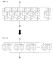
- FIG. 2 is an explanatory diagram ( 1 ) illustrating a connection for obtaining a voltage and a current by combining solar cells;
- FIG. 3 is an explanatory diagram illustrating a connection for obtaining a large current by combining solar cells
- FIG. 4 is an explanatory diagram ( 1 ) illustrating a switch circuit for enabling a combination of four solar cells
- FIG. 5 is an explanatory diagram ( 2 ) illustrating a switch circuit for enabling a combination of N solar cells
- FIGS. 6A and 6B are explanatory diagrams illustrating a method of obtaining a voltage of a single cell in the switch circuit for enabling a combination of N solar cells;
- FIGS. 7A and 7B are explanatory diagrams illustrating a method of obtaining a voltage of a pair of cells in the switch circuit for enabling a combination of N solar cells;
- FIG. 8 is a schematic block diagram illustrating a schematic configuration of a power source apparatus according to the present invention.
- FIG. 9 is an explanatory diagram illustrating an output power characteristic of a photovoltaic system
- FIG. 10 is an explanatory diagram for describing maximum power point tracking
- FIG. 11 is a schematic circuit diagram illustrating a configuration change of the photovoltaic system
- FIG. 12 is an explanatory diagram illustrating operations of the photovoltaic system and a power source 5 ;
- FIG. 13 is an explanatory diagram ( 2 ) illustrating a connection for obtaining voltage and current by combining solar cells
- FIG. 14 is an explanatory diagram illustrating a switch circuit for enabling a combination of N solar cells installed with a backflow prevention device D and an ammeter;
- FIG. 15 is a voltage-current characteristic diagram of the photovoltaic system.
- FIG. 8 is a schematic block diagram illustrating an exemplary configuration of the entire power source apparatus according to the present invention.
- a solar cell switch circuit 1 includes a plurality of solar cells of the photovoltaic system and switches capable of changing connections of the solar cells as illustrated in FIG. 5 , so that the connection of the solar cells 2 can be changed using the switches 3 and the like.
- the photovoltaic system (solar panel) has a plurality of small-sized solar cells 2 .
- a unit body of the photovoltaic system that is, the solar cell 2 is formed of polycrystalline silicon, single crystalline silicon, amorphous silicon, or the like depending on its type.
- the output voltage exhibiting the maximum power is changed depending on the type of the solar cell.
- current and voltage are obtained by connecting the solar cells 2 in series and/or in parallel.
- FIG. 1 For example, if four solar cells 2 capable of outputting a voltage of 0.5 V and a current of 100 mA under the maximum power condition are connected in series, a voltage of 2 V and a current of 100 mA can be obtained ( FIG. 1 ).
- connection may include a 4-series connection ( FIG. 1 ), a 2-series and 2-parallel connection ( FIG. 2 ), and a 4-parallel connection ( FIG. 3 ) capable of outputting voltages of 2 V, 1 V, and 0.5 V, respectively.
- FIG. 4 A configuration for changing the connection using the switches 3 is illustrated in FIG. 4 . If the connection is changed in this manner, all of the connection schemes of FIGS. 1 to 3 can be implemented by switching the switches 3 .
- FIG. 5 illustrates an exemplary connection of N solar cells.
- connection of the solar cells 3 can be changed by switching the switches 3 (SW 1 a , SW 1 b , SW 1 c , . . . , SWNa, SWNb, SWNc).
- a single solar cell 2 is connected between the terminals A and B (equivalent to the circuit of FIG. 6B ).
- the number of solar cells 2 connected between the terminals A and B can be set freely using the switches 3 .
- connection can be dynamically changed by employing a relay or a semiconductor switching element (such as a transistor or a field effect transistor (FET)) that can be controlled externally as the switch 3 .
- a relay or a semiconductor switching element such as a transistor or a field effect transistor (FET)
- FET field effect transistor
- FIG. 8 is a circuit diagram illustrating the (entire) circuit according to the present invention. The description will continue with reference to FIG. 8 .
- D denotes a backflow prevention member.
- a backflow prevention diode is employed.
- any other switching element such as a semiconductor switch (such as FET) similar to the backflow prevention diode may also be employed.
- the power source 5 is a low-impedance power source. When the generated power of the photovoltaic system is insufficient, power from the power source 5 is supplied to the load 4 .
- the switch 3 of FIG. 5 may also be a semiconductor switch as well as a mechanical switch such as a relay.
- backflow prevention diodes D 1 to DN may be inserted into the circuit of FIG. 5 as illustrated in FIG. 14 .
- semiconductor switches such as FETs
- FETs field-effect transistors
- an ammeter A may be installed to check the current.
- the connection sequence of the backflow prevention diode, the ammeter, and the switches SW 1 a to SWNa is changed (they may be inserted into the B-side instead of the A-side).
- the backflow prevention member D of the solar cell switch circuit 1 side in FIG. 8 that is, the backflow prevention diode is not necessary and may be omitted as necessary.
- the voltage can be set to 0.5 to 5 V in the unit of 0.5 V.
- the output voltage and current are shown in the following table.
- a voltage of 4.5 V can be output by connecting nine cells in series. However, a single cell 2 remains.
- the “surplus cell” in the table denotes the number of such remaining cells 2 .
- “efficiency” of the table denotes a percentage of the generated power obtained by excluding the power generated by the cell 2 that does not contribute to power generation as the surplus cell. When the number of cells 2 connected in series is set to “1,” “2,” “5,” and “10,” the surplus cell is not generated. Therefore, the efficiency becomes 100%.
- a voltage corresponding to the highest efficiency is adjusted to the voltage of the power source 5 by changing the configuration of the solar cell switch circuit 1 .
- the solar cell switch circuit 1 has the configuration of FIG. 5 , and the voltage corresponding to the highest efficiency point of the solar cell 2 is known in advance (here, “0.5 V” by way of example).
- the voltage corresponding to maximum power can be changed in the unit of approximately 0.5 V by changing the connection scheme of the solar cells 2 .
- the power source 5 outputs a voltage of 10 V
- FIG. 9 shows an output characteristic of the photovoltaic system (the relationship between the output voltage and the power).
- FIG. 12 shows a relationship between the output voltage and the output current in the same photovoltaic system.
- the output voltage In the case of a small load (that is, the current flowing through the load is small), the output voltage is high. In the case of a large load (that is, the output current is large), the output voltage is low.
- the voltage of the load 4 as seen from the photovoltaic system is “10 V,” and the current I p corresponding to the load voltage of 10 V flows on the basis of the characteristic curve of the photovoltaic system. In addition, this also corresponds to the operating point of the maximum output of the photovoltaic system.
- the power from the photovoltaic system is prioritized.
- the current I p flows from the photovoltaic system at all times, and only the amount of the deficient current is supplied from the power source 5 .
- the power source 5 may output, for example, a voltage obtained by rectifying and smoothing a voltage from a commercial AC power source.
- a DC power source of approximately 140 V can be obtained by rectifying and smoothing a voltage from a commercial AC power source of 100 V.
- a commercial AC power source of 100 V For example, assuming that solar cells of the same voltage are employed, two hundred eighty (280) solar cells 2 may be connected in series.
- the voltage of the power source 5 illustrated in FIG. 8 and the like is set to “20 V,” it is possible to set the voltage corresponding to the maximum power point of the photovoltaic system to “20 V” by connecting forty solar cells 2 in series. Since the number of the solar cells 2 is eighty, a pair of strings can be obtained. By connecting the pair of strings in parallel, it is possible to obtain a voltage of 20V and a current of 200 mA at the maximum power point.
- the current I p of FIG. 12 is 200 mA.
- the output current when the output current is larger than 200 mA, the current flows from the power source 5 . However, it is not equal to or lower than 20 V because the power source 5 has sufficiently low impedance.
- the voltage of the load 4 as seen from the photovoltaic system side is 20 V.
- a current of 200 mA corresponding to the load voltage of 20 V flows on the basis of the characteristic curve of the photovoltaic system. In addition, this also corresponds to the operating point of the maximum output of the photovoltaic system.
- the power from the photovoltaic system is prioritized.
- a current of 200 mA flows from the photovoltaic system at all times, and only the amount of the deficient current is supplied from the power source 5 .
- ammeter A is connected as illustrated in FIG. 14 , it is possible to simply perform the maximum power point tracking control on the basis of the current value and the configuration change of the photovoltaic system using the switch circuit without necessity of measuring the voltages of the power source 5 and the photovoltaic system even when the characteristic of the photovoltaic system is not known.
- the number of solar cells in a certain string is incremented by one, and the number of solar cells in another string is decremented by one ( FIG. 10 ).
- the switch setting state is expressed by wiring for simplicity purposes here.
- the backflow prevention member D, the power source 5 , and the load 4 are collectively denoted by an “output circuit” in FIG. 10 .
- the voltage between the terminals A and B is denoted by “V AB ” and the measurement values of each ammeter A are denoted by I 1 to I 7 .
- V AB the measurement values of each ammeter A
- V AB the voltage across the terminals A and B. Therefore, a voltage V 3 for a single solar cell is set to:
- V ⁇ ⁇ 3 V AB 4 .
- V ⁇ ⁇ 1 V AB 5
- V ⁇ ⁇ 2 V AB 3 .
- the power generated from a single solar cell of each string can be obtained as follows:
- P 3 denotes the power generated from a single solar cell when four solar cells are connected in series
- P 1 ′ denotes the power generated from a single solar cell when five solar cells are connected in series
- P 2 denotes the power generated from a single solar cell when three solar cells are connected in series.
- the magnitude relationship of the power values P 3 , P 1 , and P 2 is equal to the magnitude relationship of the current values I 3 / 4 , I 1 / 5 , and I 2 / 3 . Therefore, it is recognized that the power generated from a single solar cell can be compared only using the current values and the number of solar cells connected in series (a value obtained by dividing the current value by the number of solar cells connected in series).
- the system is operated without a problem even when the voltage of the power source 5 is fluctuated.
- FIG. 11 illustrates an exemplary modification of the configuration of the photovoltaic system.
- a one-chip microcomputer may be employed as a control device, and a latching type relay may be employed as the switch.
- the configuration of the photovoltaic system is modified as described above such that the current measurement value is received by the control device, and the switches are controlled on the basis of the received current measurement value.
- a surplus cell may be generated in the photovoltaic system depending on a connection scheme (setup voltage) (Formula 3).
- setup voltage setup voltage
- this can be computable. Therefore, it is possible to implement maximum efficiency using the method according to the present invention by considering this computable value in the maximum power point tracking.
- the effective number of solar cells can be expressed as follows:
- P 3 denotes a power value for a single solar cell when X solar cells are connected in series
- P 1 ′ denotes a power value for a single solar cell when (X+1) solar cells are connected in series
- P 2 denotes a power value for a single solar cell when (X ⁇ 1) solar cells are connected in series.
- the generated power of the entire photovoltaic system can be obtained as follows:
- connection can be changed to maximize these values.
- the magnitude relationship is not changed even when the power values P 3 , P 1 , and P 2 of each formula are substituted with I 3 /X, I 1 /(X+1), and I 2 /(X ⁇ 1). Therefore, it is possible to use these values for computation.
- a string having the incremented number of solar cells (+1) and a string having the decremented number of solar cells ( ⁇ 1) may be prepared periodically. Then, the power values described above are computed for each case, and a condition where the highest values can be obtained may be selected. For example, if the power value is highest when the number of solar cells connected in series is incremented (+1), a solar cell may be added (+1) to the existing array. In contrast, if the power value is highest when the number of solar cells connected in series is decremented ( ⁇ 1), a solar cell may be omitted ( ⁇ 1) from the existing array. If the power value is highest when the number of solar cells connected in series is not changed, the existing array may be maintained.
- the present invention in order to obtain the highest efficiency of the photovoltaic system, that is, in the maximum power point tracking of the photovoltaic system, it is not necessary to measure (operate) the photovoltaic system under different conditions unlike the methods of the prior art such as a hill climbing method. Therefore, it is possible to maintain high power efficiency.
- the power source apparatus can be configured just by the photovoltaic system, the switch circuit, and another type of power source.
- a power circuit for example, a power component such as a switching regulator is not necessary.
- the surplus number of solar cells 2 may influence on the maximum power point tracking. That is, as illustrated in FIG. 9 , when a graph has a single hill, tracking can be performed using the method described above. However, when two or more hills are generated due to the influence of the surplus cell 2 , the maximum power point may stay in the lower hill, and it may be difficult to find the maximum power point in the higher hill.
- the number of solar cells connected in series may be changed to the number by which the largest current can be output only using the current and the number of solar cells 2 regardless of the number of surplus cells 2 .
- the current value may be investigated for each case by changing the number of cells connected in series from the number of cells 2 by which the largest current can be output to the number having no surplus cell 2 .
Landscapes
- Engineering & Computer Science (AREA)
- Power Engineering (AREA)
- Control Of Electrical Variables (AREA)
- Photovoltaic Devices (AREA)
- Life Sciences & Earth Sciences (AREA)
- Sustainable Development (AREA)
- Sustainable Energy (AREA)
Abstract
Description
2. Method of Setting Highest Efficiency Point of Photovoltaic System.
and
and
-
- 1 solar cell switch circuit
- 2 solar cell
- 3 switch
- 4 load
- 5 power source
- D backflow prevention member
- A ammeter
Claims (2)
Applications Claiming Priority (3)
| Application Number | Priority Date | Filing Date | Title |
|---|---|---|---|
| JP2013-235985 | 2013-11-14 | ||
| JP2013235985A JP5738383B2 (en) | 2013-11-14 | 2013-11-14 | Power supply |
| PCT/JP2014/005560 WO2015072110A1 (en) | 2013-11-14 | 2014-11-05 | Power source device |
Publications (2)
| Publication Number | Publication Date |
|---|---|
| US20160301215A1 US20160301215A1 (en) | 2016-10-13 |
| US9728973B2 true US9728973B2 (en) | 2017-08-08 |
Family
ID=53057063
Family Applications (1)
| Application Number | Title | Priority Date | Filing Date |
|---|---|---|---|
| US15/036,489 Expired - Fee Related US9728973B2 (en) | 2013-11-14 | 2014-11-05 | Power source device |
Country Status (5)
| Country | Link |
|---|---|
| US (1) | US9728973B2 (en) |
| EP (1) | EP3070570A4 (en) |
| JP (1) | JP5738383B2 (en) |
| CN (1) | CN105745588A (en) |
| WO (1) | WO2015072110A1 (en) |
Families Citing this family (8)
| Publication number | Priority date | Publication date | Assignee | Title |
|---|---|---|---|---|
| WO2014147527A2 (en) * | 2013-03-22 | 2014-09-25 | Koninklijke Philips N.V. | Power management between sources and load |
| CN111418125A (en) * | 2017-09-01 | 2020-07-14 | 紫稳电机株式会社 | Power supply system and power combiner |
| WO2020102858A1 (en) * | 2018-11-22 | 2020-05-28 | Digilog Technologies Pty Ltd | Solar cell or solar panel energy extraction system |
| US12136837B1 (en) * | 2020-12-08 | 2024-11-05 | Bobbie Wilson | Charge balancing of parallel strings with zener diode and light emitting diode between cell terminal of the battery strings |
| WO2022211191A1 (en) * | 2021-04-01 | 2022-10-06 | 타임로봇 주식회사 | Intelligent photovoltaic module controller and control method thereof |
| KR102361318B1 (en) * | 2021-08-20 | 2022-02-14 | 최봉진 | Methods controlling an intelligent PV Module Controller and the power conversion device for the methods |
| KR102361319B1 (en) * | 2021-04-01 | 2022-02-14 | 최봉진 | Intelligent PV Module Controller |
| WO2023152749A1 (en) * | 2022-02-13 | 2023-08-17 | Aquarius Engines (A.M.) Ltd. | Systems and methods thereof for powering a load from a plurality of power supplies |
Citations (6)
| Publication number | Priority date | Publication date | Assignee | Title |
|---|---|---|---|---|
| JPH0583880A (en) | 1991-09-18 | 1993-04-02 | Mitsubishi Electric Corp | Power device |
| JP2000089841A (en) | 1998-09-08 | 2000-03-31 | Kobe Steel Ltd | Solar generator |
| US20010035180A1 (en) | 2000-04-28 | 2001-11-01 | Fumiya Kimura | Solar generation system |
| JP2001312319A (en) | 2000-04-28 | 2001-11-09 | Sharp Corp | Photovoltaic power generation system and boost unit used for it |
| US20100156185A1 (en) * | 2008-12-23 | 2010-06-24 | Samsung Electro-Mechanics Co., Ltd. | Photovoltaic and fuel cell hybrid generation system using single converter and single inverter, and method of controlling the same |
| WO2011041020A2 (en) | 2009-09-30 | 2011-04-07 | The Boeing Company | Diodeless terrestrial photovoltaic solar power array |
Family Cites Families (7)
| Publication number | Priority date | Publication date | Assignee | Title |
|---|---|---|---|---|
| DE10107600C1 (en) * | 2001-02-17 | 2002-08-22 | Saint Gobain | Method for operating a photovoltaic solar module and photovoltaic solar module |
| CN1933315B (en) * | 2005-07-27 | 2011-05-11 | 武藤健一 | Sun's rays generating device |
| JP4994476B2 (en) | 2010-02-08 | 2012-08-08 | 實 村野 | DC power supply system |
| EP2538522A4 (en) * | 2010-02-19 | 2014-03-19 | Honda Motor Co Ltd | POWER SUPPLY SYSTEM AND ELECTRIC VEHICLE |
| JP2012044833A (en) * | 2010-08-23 | 2012-03-01 | Sumitomo Electric Ind Ltd | Power conversion equipment and connection device |
| CA2728619A1 (en) * | 2011-01-18 | 2012-07-18 | Nazir Dosani | A renewable power control system |
| JP2012204651A (en) * | 2011-03-25 | 2012-10-22 | Sharp Corp | Solar cell module, photovoltaic power generation system, connection switching control method for solar cell in solar cell module, connection switching control program, and recording medium |
-
2013
- 2013-11-14 JP JP2013235985A patent/JP5738383B2/en not_active Expired - Fee Related
-
2014
- 2014-11-05 WO PCT/JP2014/005560 patent/WO2015072110A1/en not_active Ceased
- 2014-11-05 US US15/036,489 patent/US9728973B2/en not_active Expired - Fee Related
- 2014-11-05 EP EP14861814.3A patent/EP3070570A4/en not_active Withdrawn
- 2014-11-05 CN CN201480062161.1A patent/CN105745588A/en active Pending
Patent Citations (6)
| Publication number | Priority date | Publication date | Assignee | Title |
|---|---|---|---|---|
| JPH0583880A (en) | 1991-09-18 | 1993-04-02 | Mitsubishi Electric Corp | Power device |
| JP2000089841A (en) | 1998-09-08 | 2000-03-31 | Kobe Steel Ltd | Solar generator |
| US20010035180A1 (en) | 2000-04-28 | 2001-11-01 | Fumiya Kimura | Solar generation system |
| JP2001312319A (en) | 2000-04-28 | 2001-11-09 | Sharp Corp | Photovoltaic power generation system and boost unit used for it |
| US20100156185A1 (en) * | 2008-12-23 | 2010-06-24 | Samsung Electro-Mechanics Co., Ltd. | Photovoltaic and fuel cell hybrid generation system using single converter and single inverter, and method of controlling the same |
| WO2011041020A2 (en) | 2009-09-30 | 2011-04-07 | The Boeing Company | Diodeless terrestrial photovoltaic solar power array |
Non-Patent Citations (1)
| Title |
|---|
| International Search Report issued Jan. 27, 2015 in International (PCT) Application No. PCT/JP2014/005560. |
Also Published As
| Publication number | Publication date |
|---|---|
| CN105745588A (en) | 2016-07-06 |
| EP3070570A4 (en) | 2017-08-09 |
| JP5738383B2 (en) | 2015-06-24 |
| WO2015072110A1 (en) | 2015-05-21 |
| JP2015095227A (en) | 2015-05-18 |
| EP3070570A1 (en) | 2016-09-21 |
| US20160301215A1 (en) | 2016-10-13 |
Similar Documents
| Publication | Publication Date | Title |
|---|---|---|
| US9728973B2 (en) | Power source device | |
| US10153383B2 (en) | Solar string power point optimization | |
| US9442505B2 (en) | Electric power control apparatus, electric power control method, and electric power feeding system | |
| US8624436B2 (en) | Power harvesting circuit and method for serially coupled DC power sources | |
| KR101925528B1 (en) | Localized power point optimizer for solar cell installations | |
| US20110285375A1 (en) | Maximum Power Point Tracker Bypass | |
| US9310445B2 (en) | Power source arrangement and method of diagnosing a power source arrangement | |
| ES2874886T3 (en) | Method and apparatus for controlling solar power systems | |
| US10476274B2 (en) | Solar power generation system | |
| US20150349583A1 (en) | Solar power generation system | |
| EP2779250A2 (en) | Photovoltaic bypass and output switching | |
| EP2600406A2 (en) | Solar device | |
| US9780234B2 (en) | Photovoltaic bypass and output switching | |
| US20120101645A1 (en) | Power control method using orthogonal-perturbation, power generation system, and power converter | |
| US20240022173A1 (en) | Power conversion apparatus having multi-level structure | |
| WO2020133056A1 (en) | Central and distributed photovoltaic power plant and control system therefor | |
| US20120033466A1 (en) | Partial power micro-converter architecture | |
| KR101007283B1 (en) | Power control device and power control method for wireless sensor network | |
| US9697961B2 (en) | Photovoltaic bypass switching | |
| KR101382946B1 (en) | Photovoltaic power generation system and control method thereof | |
| KR20100098870A (en) | Photovoltaic power generation system, apparatus and method for tracking maximum power point | |
| JP2017060345A (en) | Power generating operation point control circuit device for solar batteries connected in series | |
| US20240171059A1 (en) | Power conversion device having multi-level structure | |
| US20240056022A1 (en) | Power conversion device having multi-level structure | |
| CN111800012B (en) | Operating point control circuit device for a plurality of power supply units connected in series |
Legal Events
| Date | Code | Title | Description |
|---|---|---|---|
| AS | Assignment |
Owner name: SION ELECTRIC CO., LTD., JAPAN Free format text: ASSIGNMENT OF ASSIGNORS INTEREST;ASSIGNORS:MURANO, MINORU;AKIBA, SUMINOBU;TANAHASHI, SHIN;REEL/FRAME:038704/0222 Effective date: 20151102 |
|
| STCF | Information on status: patent grant |
Free format text: PATENTED CASE |
|
| MAFP | Maintenance fee payment |
Free format text: PAYMENT OF MAINTENANCE FEE, 4TH YR, SMALL ENTITY (ORIGINAL EVENT CODE: M2551); ENTITY STATUS OF PATENT OWNER: SMALL ENTITY Year of fee payment: 4 |
|
| FEPP | Fee payment procedure |
Free format text: MAINTENANCE FEE REMINDER MAILED (ORIGINAL EVENT CODE: REM.); ENTITY STATUS OF PATENT OWNER: SMALL ENTITY |
|
| LAPS | Lapse for failure to pay maintenance fees |
Free format text: PATENT EXPIRED FOR FAILURE TO PAY MAINTENANCE FEES (ORIGINAL EVENT CODE: EXP.); ENTITY STATUS OF PATENT OWNER: SMALL ENTITY |
|
| STCH | Information on status: patent discontinuation |
Free format text: PATENT EXPIRED DUE TO NONPAYMENT OF MAINTENANCE FEES UNDER 37 CFR 1.362 |
|
| FP | Lapsed due to failure to pay maintenance fee |
Effective date: 20250808 |