US972758A - Nut-lock. - Google Patents
Nut-lock. Download PDFInfo
- Publication number
- US972758A US972758A US48525609A US1909485256A US972758A US 972758 A US972758 A US 972758A US 48525609 A US48525609 A US 48525609A US 1909485256 A US1909485256 A US 1909485256A US 972758 A US972758 A US 972758A
- Authority
- US
- United States
- Prior art keywords
- nut
- bolt
- rib
- pin
- channel
- Prior art date
- Legal status (The legal status is an assumption and is not a legal conclusion. Google has not performed a legal analysis and makes no representation as to the accuracy of the status listed.)
- Expired - Lifetime
Links
- 108010085990 projectin Proteins 0.000 description 2
- 108010002947 Connectin Proteins 0.000 description 1
- 102000004726 Connectin Human genes 0.000 description 1
- 230000001869 rapid Effects 0.000 description 1
- 239000011435 rock Substances 0.000 description 1
Images
Classifications
-
- F—MECHANICAL ENGINEERING; LIGHTING; HEATING; WEAPONS; BLASTING
- F16—ENGINEERING ELEMENTS AND UNITS; GENERAL MEASURES FOR PRODUCING AND MAINTAINING EFFECTIVE FUNCTIONING OF MACHINES OR INSTALLATIONS; THERMAL INSULATION IN GENERAL
- F16B—DEVICES FOR FASTENING OR SECURING CONSTRUCTIONAL ELEMENTS OR MACHINE PARTS TOGETHER, e.g. NAILS, BOLTS, CIRCLIPS, CLAMPS, CLIPS OR WEDGES; JOINTS OR JOINTING
- F16B39/00—Locking of screws, bolts or nuts
- F16B39/02—Locking of screws, bolts or nuts in which the locking takes place after screwing down
- F16B39/04—Locking of screws, bolts or nuts in which the locking takes place after screwing down with a member penetrating the screw-threaded surface of at least one part, e.g. a pin, a wedge, cotter-pin, screw
-
- Y—GENERAL TAGGING OF NEW TECHNOLOGICAL DEVELOPMENTS; GENERAL TAGGING OF CROSS-SECTIONAL TECHNOLOGIES SPANNING OVER SEVERAL SECTIONS OF THE IPC; TECHNICAL SUBJECTS COVERED BY FORMER USPC CROSS-REFERENCE ART COLLECTIONS [XRACs] AND DIGESTS
- Y10—TECHNICAL SUBJECTS COVERED BY FORMER USPC
- Y10S—TECHNICAL SUBJECTS COVERED BY FORMER USPC CROSS-REFERENCE ART COLLECTIONS [XRACs] AND DIGESTS
- Y10S411/00—Expanded, threaded, driven, headed, tool-deformed, or locked-threaded fastener
- Y10S411/924—Coupled nut and bolt
- Y10S411/945—Cross key
- Y10S411/946—Spring-seated
Definitions
- My invention relates to a new and useful improvement in nut locks and my object is to provide means for securely locking a nut on a bolt.
- a further object is to form the bolt so that the same may be manually released when it is desired to remove the nut.
- a further object is to provide retaining means on the nut for the locking in.
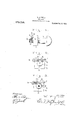
- Figure 1 is a side elevation of a bolt showing the nut thereon in locked position.
- Fig. 2 is an end elevation thereof.
- Fig. 3 is an end elevation of the same showing one arm of the locking pin bent in engagement with the bolt.
- 1 indicates a bolt, one end of which is provided with the usual form of threads 2, portions of said threads on opposite sides of the bolt being removed to form flattened portions or seats 3.
- the locking pin 6 preferably consists of a split key or cotter pin, the arms 7 and 8 of which are normally spread apart by the spring tension of the connectin head 9, so that when the locking pin is introduced between the bolt and t e rib on the nut,
- the lower face of the rib being provided with a curved channel 10. which engages the curved face of the arms 7 and 8 and holds the pin against moving edge-wise from below the rib, while the pin is held normally against longitudinal movement by inclining the channel 10, from that end of the rib which is engaged by the head 9 to the opposite end of the channel.
- the free end of the arm 8 may be forced downwardly as best shown b dotted lines in Fig. 2, thereby securely loc ing the pin in position between the bolt and rib.
- a bolt having a mutilated threaded portion said portion having fiattened surfaces thereon removing complete segments from said bolt, a nut applied to said bolt having a transverse rib projectin from the up er edge of one of its faces an a bifurcate spring in inserted between said projecting rib an one of said flattened surfaces, the under face of said projectin rib being concaved to form a channel an said channel inclined from one edge to the opposite side edge of said nut, whereby said bolt, the arms of said pin conforming 'in outline to the curvature of said channel and said head engaging one end of said rib, said channel being inclined from that end of the rib engaged by said head to the 0pposite end of the channel, whereby longitndinal and lateral movement of said spring 'pin is prevented.
Description
W. FIFIELD.
NUT LOCK. APPLICATION FILED MAR. 23, 1909.
Patented Oct. 11, 1910.
8 R W i m M [all I V WITNESSES of which is provided a rib 5,.said rib exf 'Ada ted to take onto the threaded portion WARREN FIFIELD, 0F SAUK RAPIDS, MINNESOTA, ASSIGNOR OF ONE-THIRD WEBER, OF CASTLE ROCK, WASHINGTON.
TO A. J.
NUT-LOCK.
To all whom it may concern:
Be. it known that I, WARREN FIFIELmE a citizen of the United States, residing at Sauk Rapids, in the county of Benton and I State of Minnesota, have invented certain new and useful Improvements in Nut- Locks; and I do hereby declare the following to be a full, clear, and exact description of the invention, such as will enable others skilled in the art to which it appertains to make and use the same.
My invention relates to a new and useful improvement in nut locks and my object is to provide means for securely locking a nut on a bolt.
A further object is to form the bolt so that the same may be manually released when it is desired to remove the nut.
A further object is to provide retaining means on the nut for the locking in.
Other objects and advantages wil be hereinafter referred to and more particularly pointed out in the claims.
In the accompanying drawings forming part of this application, Figure 1 is a side elevation of a bolt showing the nut thereon in locked position. Fig. 2 is an end elevation thereof. Fig. 3 is an end elevation of the same showing one arm of the locking pin bent in engagement with the bolt.
Referring to the drawings in which similar-reference numerals designate corresponding parts throughout the several views, 1 indicates a bolt, one end of which is provided with the usual form of threads 2, portions of said threads on opposite sides of the bolt being removed to form flattened portions or seats 3.
of the olt 1 is a nut 4:, on the forward face tending across the front face of the nut, between which and the seats 3 on the bolt, is adapted to be introduced a locking pin 6. The locking pin 6 preferably consists of a split key or cotter pin, the arms 7 and 8 of which are normally spread apart by the spring tension of the connectin head 9, so that when the locking pin is introduced between the bolt and t e rib on the nut,
are
spring tension will be exerted on the arms Specification of Letters Patent. Patented 09$ 3 g; 5910.
Application filed March 23,
1909. Serial No. 485,256.
and hold the same in close relationship with the rib and bolt, respectively, the lower face of the rib being provided with a curved channel 10. which engages the curved face of the arms 7 and 8 and holds the pin against moving edge-wise from below the rib, while the pin is held normally against longitudinal movement by inclining the channel 10, from that end of the rib which is engaged by the head 9 to the opposite end of the channel.
After the locking pin has been properly seated,'the free end of the arm 8 may be forced downwardly as best shown b dotted lines in Fig. 2, thereby securely loc ing the pin in position between the bolt and rib.
At such time as it is desired to remove the nut from the bolt, in re-adjust .the same the bent-down portion inay be straightened and, the pin driven lengthwise from between the rib and bolt, when the nut may be readily turned to remove the same from the bolt or tightened as occasion may require.
What I claim is:
1. A device of the character described,
comprising a bolt having a mutilated threaded portion, said portion having fiattened surfaces thereon removing complete segments from said bolt, a nut applied to said bolt having a transverse rib projectin from the up er edge of one of its faces an a bifurcate spring in inserted between said projecting rib an one of said flattened surfaces, the under face of said projectin rib being concaved to form a channel an said channel inclined from one edge to the opposite side edge of said nut, whereby said bolt, the arms of said pin conforming 'in outline to the curvature of said channel and said head engaging one end of said rib, said channel being inclined from that end of the rib engaged by said head to the 0pposite end of the channel, whereby longitndinal and lateral movement of said spring 'pin is prevented.
WARREN FIFIELD.
Witnesses THOMAS VAN ETTEN, HARRY GRIMNSER.
Priority Applications (1)
| Application Number | Priority Date | Filing Date | Title |
|---|---|---|---|
| US48525609A US972758A (en) | 1909-03-23 | 1909-03-23 | Nut-lock. |
Applications Claiming Priority (1)
| Application Number | Priority Date | Filing Date | Title |
|---|---|---|---|
| US48525609A US972758A (en) | 1909-03-23 | 1909-03-23 | Nut-lock. |
Publications (1)
| Publication Number | Publication Date |
|---|---|
| US972758A true US972758A (en) | 1910-10-11 |
Family
ID=3041138
Family Applications (1)
| Application Number | Title | Priority Date | Filing Date |
|---|---|---|---|
| US48525609A Expired - Lifetime US972758A (en) | 1909-03-23 | 1909-03-23 | Nut-lock. |
Country Status (1)
| Country | Link |
|---|---|
| US (1) | US972758A (en) |
Cited By (1)
| Publication number | Priority date | Publication date | Assignee | Title |
|---|---|---|---|---|
| US6257551B1 (en) * | 1999-05-26 | 2001-07-10 | Watts Investment Company | Valve stem extension |
-
1909
- 1909-03-23 US US48525609A patent/US972758A/en not_active Expired - Lifetime
Cited By (1)
| Publication number | Priority date | Publication date | Assignee | Title |
|---|---|---|---|---|
| US6257551B1 (en) * | 1999-05-26 | 2001-07-10 | Watts Investment Company | Valve stem extension |
Similar Documents
| Publication | Publication Date | Title |
|---|---|---|
| US972758A (en) | Nut-lock. | |
| US3490508A (en) | Nut or bolt retainer | |
| US712905A (en) | Nut-lock. | |
| US589599A (en) | Nut-lock | |
| US1301958A (en) | Nut and bolt lock. | |
| US439754A (en) | Nut-lock | |
| US295960A (en) | Nut and bolt lock | |
| US230009A (en) | Nut-lock | |
| US1134520A (en) | Nut-lock. | |
| US1020026A (en) | Nut-lock. | |
| US204731A (en) | Improvement in nut-locks | |
| US159508A (en) | Improvement in nut-locks | |
| US642066A (en) | Nut-lock. | |
| US602724A (en) | Bolt-nut | |
| US666065A (en) | Nut-lock. | |
| US862310A (en) | Holding-pin for toggle-bolts and the like. | |
| US1358690A (en) | Nut-lock | |
| US1020322A (en) | Bench-screw. | |
| US1527552A (en) | Nut lock | |
| US1571037A (en) | Nut lock | |
| US662343A (en) | Nut-lock. | |
| US577174A (en) | Nut-lock | |
| US605861A (en) | Nut-lock | |
| US258497A (en) | ste yens | |
| US1075605A (en) | Nut-lock. |