US972749A - Lock for journal-box lids. - Google Patents
Lock for journal-box lids. Download PDFInfo
- Publication number
- US972749A US972749A US1910548152A US972749A US 972749 A US972749 A US 972749A US 1910548152 A US1910548152 A US 1910548152A US 972749 A US972749 A US 972749A
- Authority
- US
- United States
- Prior art keywords
- cylinder
- door
- journal
- slot
- lock
- Prior art date
- Legal status (The legal status is an assumption and is not a legal conclusion. Google has not performed a legal analysis and makes no representation as to the accuracy of the status listed.)
- Expired - Lifetime
Links
Images

Classifications
-
- B—PERFORMING OPERATIONS; TRANSPORTING
- B61—RAILWAYS
- B61F—RAIL VEHICLE SUSPENSIONS, e.g. UNDERFRAMES, BOGIES OR ARRANGEMENTS OF WHEEL AXLES; RAIL VEHICLES FOR USE ON TRACKS OF DIFFERENT WIDTH; PREVENTING DERAILING OF RAIL VEHICLES; WHEEL GUARDS, OBSTRUCTION REMOVERS OR THE LIKE FOR RAIL VEHICLES
- B61F15/00—Axle-boxes
- B61F15/20—Details
- B61F15/26—Covers; Sealing thereof
-
- Y—GENERAL TAGGING OF NEW TECHNOLOGICAL DEVELOPMENTS; GENERAL TAGGING OF CROSS-SECTIONAL TECHNOLOGIES SPANNING OVER SEVERAL SECTIONS OF THE IPC; TECHNICAL SUBJECTS COVERED BY FORMER USPC CROSS-REFERENCE ART COLLECTIONS [XRACs] AND DIGESTS
- Y10—TECHNICAL SUBJECTS COVERED BY FORMER USPC
- Y10T—TECHNICAL SUBJECTS COVERED BY FORMER US CLASSIFICATION
- Y10T292/00—Closure fasteners
- Y10T292/03—Miscellaneous
Definitions
- This invention relates to journal boxes for car wheel axles, and the principal object of the same is to provide means whereby the door thereof may be securely locked to prevent unauthorized access being had to the box.
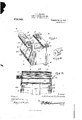
- FIG. 1 is a perspective View of the improved journal box.
- Fig. 2 is a similar view taken on the line 33, of Fig. 1.
- Fig. 3 is a vertical sectional view taken on the line 2-2, of Fig. 3.
- Fig. 4 is a view similar to Fig. 1, the locking cylinders being broken away.
- Fig. 5 is a detail perspective view of the outer cylinder of the lock.
- Fig. 6 is a fragmentary detail perspective view of the inner cylinder of the lock.
- 1 designates the journal box which has the usual door 2 hinged thereto.
- Top and bottom strips 34 extend across the rear portion of said box, said strips having their projecting ends connected by the bolts 5 and nut 6.
- Supporting bars 7-8 are clamped to the upper surface of strip 3 by the bolts 5.
- Said bars are each equipped with a shoulder 9 that engages the head of the clamping bolts, so that rotation of said bolts is prevented.
- Said bars 7-8 are of duplicate construction and extend parallel with the upper end of the sides of the box 1 and at the forward end of said box, projects upward and thence outward to provide bearing arms 10-11.
- Arm 10 has an annular opening 12 in it and arm 11 is provided with a square opening 13.
- the lock for the door 2 is composed of an outer cylinder 14 and an inner cylinder 15.
- Cylinder 14 has a cylindrical tube extension 16 that projects from its closed end 17 internally threaded and is mounted in the opening 12 of arm 10.
- Cylinder 15 is fitted within cylinder 14 and has a shaft 18 extending through it one end of said shaft being threaded and engaging the threaded portion of tube extension 16.
- the opposite end of shaft 18 is squared, as indicated at 19, and projects through the closed end of cylinder 15 and is mounted in opening 13 of arm 11.
- a pin 20 is adapted to be passed through an opening 21 in the squared end of shaft 18 to retain the same in engagement with arm 11.
- Cylinder 15 is provided with a longitudinal slot 22, and cylinder 14 is provided with a transverse centrally located slot 23 that extends partly around the same, one end of said slot communicating with a short, central longitudinal slot 24.
- Door 2 has a plate 25 fastened to the central portion of its outer surface, the free end 26 of said plate being curved to conform to the contour of the locking cylinders and projects over the same so that it will shield slots 23 and 24.
- Said plate has a latch 27 fastened thereto whose angular head 28 is adapted to be passed through slot 24 of cylinder 14, and by rotating said cylinder, said head engages behind the edges of slot 23, thereby retaining door 2 closed.
- Springs 29 connect door 2 to lugs 30 that project from arms 10-11, said springs constantly exerting a pressure tending to swing the door to an open position.
- cylinder 14 is rotatable and cylinder 15 stationary. But the engagement between shaft 18 of cylinder 15 and the sleeve 16 of cylinder 14 being a threaded one, it will be clear that cylinder 14 can only be rotated by using a wrench or other similar turning tool on the portion 16.
- slot 24 of cylinder 14 is alined with slot 22 of cylinder 15.
- the head 28 of latch 27 is passed through said slots, and by means of a suitable turning tool, cylinder 14 is rotated to cause its slot 24 to move out of alinement with slot 22, whereupon the latch 27 will enter slot 23 and its head engage cylinder 14 upon opposite longitudinal sides of slot 23, thereby locking door 2 in a closed position.
- a reversal of this operation will cause slots 22 and 24 to aline and the springs 29 will automatically open the door.
- a locking device for doors of journal boxes comprising telescopically arranged cylinders supported by a journal box one of said cylinders being rotatable and the other stationary, said cylinders provided with latch receiving slots, and a journal box door latch adapted for engagement with said slots.
- a door locking device forjournal boxes comprising a stationary and a rotatable cylinder supported in telescopic relation, the stationary cylinder provided with a longitudinal slot and the rotatable cylinder provided with a central slot and a communicating longitudinal slot, and a door latch having a head adapted to be passed through said longitudinal slots when in alinement, and retained in said cylinder by rotating the rotatable cylinder.
- a door locking device for journal boxes comprising a pair of locking cylinders adapted to be supported by a journal box, said cylinders provided with latch-receiving slots, a plate adapted to be connected to a door and projected over said slots, and a latch carried by said plate for engagement with said slots.
- a device of the character described comprising a pair of supporting arms, a cylinder having an internally threaded tubular end extension that is rotatably mounted in one of said arms, said cylinder provided with a latch receiving slot, a second cylin der fitted within the first mentioned cylinder and provided with a slot, a shaft extending through the inc-losed cylinder and having one end threaded for engagement with said tubular extension, the other end of said shaft being fastened to the other supporting arm, and a latch for engagement with the slots of said cylinders.
Description
L. L. BROWN.
LOCK FOR JOURNAL BOX LIDS. APPLICATION FILED MAR.9,.1810.
972F499 Peitented 001;. 11,1910.
2 SKBETSr-SHBBT 1.
' 16072 aficill3row2z was cm, WASHINGTON, DJ;
L. BROWN.
LOCK FOR JOURNAL BOX LIDS.
APPLICATION FILED MAB. 9, 1910.
972,749. Patented 001:. 11,1910.
2 SKBETS-SHEET 2.
3 a. a Q
,1: eoizcz cZ A Brown.
LEONARD L. BROWN, OF CLIFTON FOR-GE, VIRGINIA, ASSIGNOR OF ONE-FOURTH TO GEORGE '1. SIGLER, OF CLIFTON FORGE, VIRGINIA, AND THREE-FOURTHS TO WIL- LIAM T. SIGLER.
LOOK FOR JOURNAL-BOX LIDS.
Specification of Letters Patent.
Application filed March 9, 1910.
Patented Oct. 11, 1910.
Serial No. 548,152.
To all whom it may concern:
Be it known that I, LEONARD L. BROWN, a citizen of the United States of America, residing at Clifton Forge, in the county of Alleghany and State of Virgina, have invented certain new and useful Improvements in Looks for Journal-Box Lids, of which the following is a specification, reference being had therein to the accompanying drawing.
This invention relates to journal boxes for car wheel axles, and the principal object of the same is to provide means whereby the door thereof may be securely locked to prevent unauthorized access being had to the box.
In carrying out the objects of the invention generally stated above it will be understood, of course, that the essential features thereof are necessarily susceptible of changes in details and structural arrangements, one preferred and practical embodiment of which is shown in the accompanying drawings, wherein Figure 1 is a perspective View of the improved journal box. Fig. 2 is a similar view taken on the line 33, of Fig. 1. Fig. 3 is a vertical sectional view taken on the line 2-2, of Fig. 3. Fig. 4 is a view similar to Fig. 1, the locking cylinders being broken away. Fig. 5 is a detail perspective view of the outer cylinder of the lock. Fig. 6 is a fragmentary detail perspective view of the inner cylinder of the lock.
Referring to said drawings by numerals, 1 designates the journal box which has the usual door 2 hinged thereto. Top and bottom strips 34 extend across the rear portion of said box, said strips having their projecting ends connected by the bolts 5 and nut 6. Supporting bars 7-8 are clamped to the upper surface of strip 3 by the bolts 5. Said bars are each equipped with a shoulder 9 that engages the head of the clamping bolts, so that rotation of said bolts is prevented. Said bars 7-8 are of duplicate construction and extend parallel with the upper end of the sides of the box 1 and at the forward end of said box, projects upward and thence outward to provide bearing arms 10-11. Arm 10 has an annular opening 12 in it and arm 11 is provided with a square opening 13.
The lock for the door 2 is composed of an outer cylinder 14 and an inner cylinder 15.
' Cylinder 14 has a cylindrical tube extension 16 that projects from its closed end 17 internally threaded and is mounted in the opening 12 of arm 10. Cylinder 15 is fitted within cylinder 14 and has a shaft 18 extending through it one end of said shaft being threaded and engaging the threaded portion of tube extension 16. The opposite end of shaft 18 is squared, as indicated at 19, and projects through the closed end of cylinder 15 and is mounted in opening 13 of arm 11. A pin 20 is adapted to be passed through an opening 21 in the squared end of shaft 18 to retain the same in engagement with arm 11.
Springs 29 connect door 2 to lugs 30 that project from arms 10-11, said springs constantly exerting a pressure tending to swing the door to an open position.
It will be understood from the foregoing that cylinder 14 is rotatable and cylinder 15 stationary. But the engagement between shaft 18 of cylinder 15 and the sleeve 16 of cylinder 14 being a threaded one, it will be clear that cylinder 14 can only be rotated by using a wrench or other similar turning tool on the portion 16.
To look the door, slot 24 of cylinder 14 is alined with slot 22 of cylinder 15. The head 28 of latch 27 is passed through said slots, and by means of a suitable turning tool, cylinder 14 is rotated to cause its slot 24 to move out of alinement with slot 22, whereupon the latch 27 will enter slot 23 and its head engage cylinder 14 upon opposite longitudinal sides of slot 23, thereby locking door 2 in a closed position. A reversal of this operation will cause slots 22 and 24 to aline and the springs 29 will automatically open the door.
hat I claim as my invention is 1. A locking device for doors of journal boxes comprising telescopically arranged cylinders supported by a journal box one of said cylinders being rotatable and the other stationary, said cylinders provided with latch receiving slots, and a journal box door latch adapted for engagement with said slots.
2. A door locking device forjournal boxes, comprising a stationary and a rotatable cylinder supported in telescopic relation, the stationary cylinder provided with a longitudinal slot and the rotatable cylinder provided with a central slot and a communicating longitudinal slot, and a door latch having a head adapted to be passed through said longitudinal slots when in alinement, and retained in said cylinder by rotating the rotatable cylinder.
3. A door locking device for journal boxes comprising a pair of locking cylinders adapted to be supported by a journal box, said cylinders provided with latch-receiving slots, a plate adapted to be connected to a door and projected over said slots, and a latch carried by said plate for engagement with said slots.
4. A device of the character described comprising a pair of supporting arms, a cylinder having an internally threaded tubular end extension that is rotatably mounted in one of said arms, said cylinder provided with a latch receiving slot, a second cylin der fitted within the first mentioned cylinder and provided with a slot, a shaft extending through the inc-losed cylinder and having one end threaded for engagement with said tubular extension, the other end of said shaft being fastened to the other supporting arm, and a latch for engagement with the slots of said cylinders.
5. In a device of the character described, the combination with a journal box and the door thereof, of supporting bars fastened to the upper surface thereof and projecting on each side of said surface, said bars terminating in arms at their free ends which overhang said door, latch engaging means carried by said arms and a latch carried by said door.
In testimony whereof I hereunto aflix my signature in presence of two witnesses.
LEONARD L. BROWN.
lVitnesses GEORGE T. SIGLER,
J. G. FRY.
Priority Applications (1)
| Application Number | Priority Date | Filing Date | Title |
|---|---|---|---|
| US1910548152 US972749A (en) | 1910-03-09 | 1910-03-09 | Lock for journal-box lids. |
Applications Claiming Priority (1)
| Application Number | Priority Date | Filing Date | Title |
|---|---|---|---|
| US1910548152 US972749A (en) | 1910-03-09 | 1910-03-09 | Lock for journal-box lids. |
Publications (1)
| Publication Number | Publication Date |
|---|---|
| US972749A true US972749A (en) | 1910-10-11 |
Family
ID=3041129
Family Applications (1)
| Application Number | Title | Priority Date | Filing Date |
|---|---|---|---|
| US1910548152 Expired - Lifetime US972749A (en) | 1910-03-09 | 1910-03-09 | Lock for journal-box lids. |
Country Status (1)
| Country | Link |
|---|---|
| US (1) | US972749A (en) |
-
1910
- 1910-03-09 US US1910548152 patent/US972749A/en not_active Expired - Lifetime
Similar Documents
| Publication | Publication Date | Title |
|---|---|---|
| US1243115A (en) | Door-fastening means. | |
| US2185084A (en) | License plate holder | |
| US972749A (en) | Lock for journal-box lids. | |
| US2154118A (en) | Closure cap | |
| US1858893A (en) | Lock | |
| US966195A (en) | Multiple door-bolt. | |
| US1942176A (en) | Lock | |
| US1381726A (en) | Steering-wheel lock | |
| US1216660A (en) | Bicycle-lock. | |
| US1609466A (en) | Automobile hanging trunk | |
| US1854488A (en) | Tire lock assembly | |
| US1328874A (en) | Deck-sash support | |
| US2763343A (en) | Door structure for a rendering cooker or the like | |
| US1920848A (en) | Lock mechanism | |
| US1404263A (en) | Motometer lock | |
| US2027728A (en) | Vehicle wheel and tire lock | |
| US879137A (en) | Car-axle-box lid. | |
| US1507069A (en) | Vehicle lock | |
| US812866A (en) | Means for preventing theft of brasses from railway journal-boxes. | |
| US1305277A (en) | Locking means for motor-vehicles | |
| US864983A (en) | Spare-tire holder for automobiles. | |
| US1450943A (en) | Automobile lock | |
| US1522583A (en) | Lock-lid journal box | |
| US1094085A (en) | Tire-holder for automobiles, &c. | |
| US1443662A (en) | Vehicle locking device |