US9726657B2 - Pullout apparatus and system for testing of anchor bolts/bars - Google Patents
Pullout apparatus and system for testing of anchor bolts/bars Download PDFInfo
- Publication number
- US9726657B2 US9726657B2 US14/594,509 US201514594509A US9726657B2 US 9726657 B2 US9726657 B2 US 9726657B2 US 201514594509 A US201514594509 A US 201514594509A US 9726657 B2 US9726657 B2 US 9726657B2
- Authority
- US
- United States
- Prior art keywords
- base plate
- pullout
- anchor
- diameter
- utm
- Prior art date
- Legal status (The legal status is an assumption and is not a legal conclusion. Google has not performed a legal analysis and makes no representation as to the accuracy of the status listed.)
- Expired - Fee Related
Links
Images


Classifications
-
- G—PHYSICS
- G01—MEASURING; TESTING
- G01N—INVESTIGATING OR ANALYSING MATERIALS BY DETERMINING THEIR CHEMICAL OR PHYSICAL PROPERTIES
- G01N33/00—Investigating or analysing materials by specific methods not covered by groups G01N1/00 - G01N31/00
- G01N33/38—Concrete; Lime; Mortar; Gypsum; Bricks; Ceramics; Glass
- G01N33/383—Concrete or cement
-
- G—PHYSICS
- G01—MEASURING; TESTING
- G01N—INVESTIGATING OR ANALYSING MATERIALS BY DETERMINING THEIR CHEMICAL OR PHYSICAL PROPERTIES
- G01N3/00—Investigating strength properties of solid materials by application of mechanical stress
- G01N3/08—Investigating strength properties of solid materials by application of mechanical stress by applying steady tensile or compressive forces
Definitions
- pullout testing In construction technology, pullout testing generally establishes the holding force of anchors and fixings in most construction materials, such as concrete. In conventional pullout testing of anchor bolts/bars require applying a specific tensile load to an anchor bolt/bar in order that the bolt/bar can sustain such a test condition for a period of time. Deformation of the anchor tested can also be measured to understand the relationship between force and displacement during testing.
- FIG. 1 is a schematic view of a conventional pullout apparatus 100 for pullout testing of anchor bolts/bars from a concrete structure 130 .
- the conventional pullout apparatus 100 is attached via a weld point 120 to an anchor 125 embedded in concrete 130 or the like.
- Hydraulic feed lines 110 are connected to a center hold jack 115 or the like.
- a load cell 105 is disposed atop the center hold jack 115 with a support rod 107 which is connected to the weld point 120 and passes through load cell 105 and jack 115 .
- Load cell 105 is connected to an output line 113 which is configured to read the load applied to anchor 125 during testing.
- the anchor 125 may be disposed in a concrete block or wall 130 for pullout testing purposes.
- the load cell 105 may be a LVDT and the output line 113 may be connected to a data acquisition system (not shown). Further, feed lines 110 may be connected to pressure gauges (not shown).
- Embodiments include a pullout apparatus, having a plurality of bracing rods connected to a first base plate at a proximal end of the plurality of bracing rods.
- the apparatus also includes a second base plate connected at a distal end of the plurality of bracing rods.
- the apparatus further includes a reaction rod attached to the first base plate extending away from the plurality of bracing rods.
- the apparatus also includes a sample specimen mounting location disposed between the first base plate and the second base plate.
- the apparatus further includes an anchor disposed through the second base plate and configured to be fixed within a sample specimen mounted at the sample specimen mounting location.
- Embodiments include a pullout test system, having a pullout apparatus.
- the pullout apparatus includes a plurality of bracing rods connected to a first base plate at proximal end of the plurality of bracing rods.
- the apparatus also includes a second base plate connected at a distal end of the plurality of bracing rods.
- the apparatus further includes a reaction rod attached to the first base plate extending away from the plurality of bracing rods.
- the apparatus also includes a sample specimen mounting location disposed between the first base plate and the second base plate.
- the apparatus further includes an anchor disposed through the second base plate and configured to be fixed within a sample specimen mounted at the sample specimen location.
- the pullout test system includes a universal testing machine (UTM) connected to the pullout apparatus.
- UPM universal testing machine
- FIG. 1 is a schematic view of a conventional pullout apparatus for pullout testing of anchor bolts/bars from a concrete structure.
- FIG. 2A is a perspective view of a pullout apparatus for pullout testing of anchor bolts/bars from a specimen according to certain embodiments of the disclosure.
- FIG. 2B is a top schematic view of the pullout apparatus of FIG. 2A according to certain embodiments of the disclosure.
- FIG. 2C is a schematic side view of a pullout apparatus according to another embodiment of the disclosure.
- FIG. 2D is a perspective view of the pullout apparatus of FIG. 2C according to another embodiment of the disclosure.
- FIG. 3A is a schematic view of a universal testing machine (UTM) according to certain embodiments of the disclosure.
- FIG. 3B is a partial schematic view of the universal testing machine (UTM) of FIG. 3A showing the pullout apparatuses of FIGS. 2A to 2D mounted therein according to certain embodiments of the disclosure.
- UTM universal testing machine
- FIG. 4 is a block diagram of a control system for the UTM according to certain embodiments of the disclosure.
- Pullout apparatuses 200 or 201 as shown in FIGS. 2A to 2D and a universal testing machine (UTM) 300 as shown in FIG. 3 can be configured, for example, to conduct anchor pullout strength testing of specimens.
- Traditionally such testing requires a hydraulic jack, pressure gauge, data acquisition system (DAS), data storage and management system (DSMS), LVDT and specialized manpower as shown in FIG. 1 .
- DAS data acquisition system
- DSMS data storage and management system
- LVDT specialized manpower
- the pullout apparatuses 200 or 201 coupled with the UTM 300 the above mentioned traditional equipment can be replaced and the laboratory pullout strength testing for concrete anchor bars and anchor bolts can be made time and cost effective, efficient and will not require specialized labor.
- the need of separate data storage and management device can be eradicated and real-time displacement verses strength graph can be obtained.
- Pullout apparatuses 200 or 201 can be used to carry out pullout testing of an anchor rod/bar 225 using the universal testing machine 300 whereas traditional testing practice is to use an assembly of hydraulic jack, reaction frame, load cells and data acquisition system, which is expensive to setup and requires skilled labor.
- traditional testing practice is to use an assembly of hydraulic jack, reaction frame, load cells and data acquisition system, which is expensive to setup and requires skilled labor.
- using the pullout apparatus 200 of the present disclosure will result in a simple setup without the need for a complex reaction frame, load cell, hydraulic jack and data acquisition system, which will lead to a much more economical pullout test.
- the pullout apparatus 200 results in a non-destructive test to evaluate the load carrying capacity of the anchor rod/bar 225 .
- FIG. 2A is a perspective schematic view of a pullout apparatus 200 for pullout testing of anchor bolts/bars from a specimen according to certain embodiments of the disclosure.
- pullout apparatus 200 includes a reaction rod 205 , a first metal support plate 210 , a plurality of bracing rods 215 , a specimen 220 , an anchor 225 , and a second metal support plate 230 .
- first metal support plate 210 and the second metal support plate 230 are comprised of high strength steel or the like to withstand the tensile forces applied to the anchor 225 .
- Anchor 225 may be configured as a bolt, rod or bar and embedded within specimen 220 .
- Specimen 220 may comprise various forms of reinforced concrete, such as that found in various support structures, for example, garage floors, and other building structures.
- specimen 220 may be configured as a cylinder to be mounted within pullout apparatuses 200 or 201 at the second metal support plate 230 , as shown in FIGS. 2A and 2C .
- Reaction rod 205 may comprise a high strength steel rod or bar welded to the first metal support plate 210 .
- the plurality of bracing rods 215 may include a number of spaced-apart metal rods comprised of high strength steel welded at their distal ends to the second metal support plate 230 and having screw threaded proximal ends with bolted on nuts above and below the plane of the first metal support plate 210 .
- the first metal support plate 210 is configured to be removable from pullout apparatus 200 .
- second metal support plate 230 may be similarly configured to be removable from pullout apparatus 200 .
- first and second metal support plates 210 , 230 are arranged in parallel planes to each other in exemplary embodiments.
- first and second metal support plates 210 , 230 may be configured to be fixed to the plurality of bracing rods 215 via welds or via bolted on nuts.
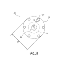
- FIG. 2B is a top schematic view of the pullout apparatus 200 of FIG. 2A according to certain embodiments of the disclosure.
- the plurality of bracing rods 215 are shown in relation to the reaction rod 205 , the second metal support plate 230 and the concrete cylinder specimen 220 .
- the second metal support plate 230 , the concrete cylinder specimen 220 and the reaction rod 205 are coaxially arranged in the pullout apparatus 200 to more evenly distribute tensile forces during testing.
- the plurality of bracing rods 215 are shown to be six rods, however, a configuration of at least two rods may suffice based on the amount of tensile forces to be applied to the specimen during testing.
- the bracing rods 215 may diametrically measure (D 2 ) at or about 25 millimeters (mm)
- the anchor 225 may diametrically measure (D 3 ) at or about 20 with a maximum of 25 mm
- the first and second steel support plates 210 , 230 may diametrically measure (D 1 ) at or about 300 mm
- the specimen 220 may diametrically measure at or about 150 mm, for example.
- These dimensions may provide maximum rigidity of pullout apparatus 200 while minimizing the amount and cost of materials used during testing. Of course, other proportionally related dimensions may be used depending on the tests to be run and the materials comprising the specimen 220 and the anchor 225 .
- second metal support plate 230 includes an opening having a diameter at or about 30 mm, the opening being configured to allow the embedded anchor 225 to pass there through.
- FIG. 2C is a schematic view of a pullout apparatus 201 according to another embodiment of the disclosure.
- pullout apparatus 201 includes a pair of mounting nuts 215 a screwed onto the proximal ends of each of the plurality of bracing rods 215 at locations immediately above and below the first metal support plate 210 .
- the plurality of bracing rods 215 are welded at 215 b to the second metal support plate 230 .
- Weld 215 b coincides with the distal ends of the plurality of bracing rods 215 .
- the first metal support plate 210 may be removable and/or replaceable in order to accommodate different configurations or changes in the sample specimen's size or material as well as accommodating any different spaced bracing rod configurations.
- FIG. 2D is a perspective view of the pullout apparatus 201 of FIG. 2C according to another embodiment of the disclosure.
- the pullout apparatus 201 may be configured such that, for example, the reaction rod 205 diametrically measures at or about 25 mm, the bracing rods 215 diametrically measure at or about 25 mm, the first and second metal support plates 210 , 230 diametrically measure at or about 300 mm with a thickness in the axial direction of the bracing rods 215 of at or about 25 mm, and the specimen 220 diametrically measures at or about 150 mm across and measures at or about 300 mm in an axial direction.
- the thicknesses of the first and second metal support plates 210 , 230 may be configured such that the first metal support plate 210 is thicker in an axial direction than the second metal support plate 230 to provide increased strength when apparatus 201 is placed under tension during a pullout test.
- FIG. 3A is a schematic view of a universal testing machine (UTM) 300 according to certain embodiments of the disclosure.
- the UTM 300 includes a first crosshead 305 , a load cell 310 , support columns 315 , a first grip 320 a , a second grip 320 b , a second crosshead 325 , a recirculating ball screw system 330 , a protective sleeve 335 , a gearbox 340 , a DC/AC servomotor 345 , a base support 350 , and a control system 355 .
- UTM universal testing machine
- the first and second crossheads 305 , 325 may be configured as movable members controlled to move up or down, usually at a constant speed. Some universal testing machines may program the crosshead speed or conduct cyclical testing, testing at constant force, testing at constant deformation, etc. Further, electromechanical, servo-hydraulic, linear drives, and resonance drives may be used.
- Load cell 310 is a force transducer or the like configured to measure an applied load. Load cell 310 may require period calibration to maintain its accuracy.
- Support columns 315 often referred to as the load frame, may consist of two strong supports for the UTM 300 .
- First grip 320 a and second grip 320 b may be configured as tensile test grips or specimen holding jaws for performing a tensile test or the like.
- FIG. 3B is a partial schematic view of the universal testing machine (UTM) 300 of FIG. 3A showing the pullout apparatus 200 of FIGS. 2A to 2D mounted therein according to certain embodiments of the disclosure.
- the pullout apparatus 200 is securely mounted between grips 320 a and 320 b to perform a tensile test via the UTM 300 .
- reaction rod 205 is mounted in grip 320 a and anchor 225 is mounted in grip 320 b .
- grip 320 a may remain fixed while grip 320 b may be configured to move away from grip 320 a via the movement of the second crosshead 325 in an opposing direction to first crosshead 305 .
- load cell 310 is configured to measure the applied load via force transducers (not shown) while the control system 355 records the load data and the displacement data during each test until anchor 225 is pulled out of specimen 220 or any other test constraints or conditions are met.
- grip 320 a may be configured to move while grip 320 b remains fixed or both grips 320 a , 320 b may be configured to move in opposing directions.
- DC/AC servomotor 345 is configured to cause gearbox 340 to rotate a drive belt which in turn causes the recirculating ball screw system 330 to move crosshead 325 up or down along support columns 315 during operation, thereby moving grip 320 b.
- FIG. 4 is a block diagram of a control system 400 for the universal testing machine (UTM) 300 according to certain embodiments of the disclosure.
- the control system 400 (similar to control system 355 of FIG. 3A ) includes a computer 405 , a monitor 410 , a printer 415 , a controller 420 , a measuring circuit 425 , a displacement sensor 430 , an amplifier 435 , a bridge circuit 440 , a servo amplifier 445 , and a power supply 450 .
- the load cell 310 and the DC servomotor 345 having an encoder 347 are connected to the control system 400 .
- the control system 400 of the UTM 300 performs the driving control and the measurement process of the UTM 300 .
- the servo amplifier 445 generates a driving current for driving the DC servomotor 345 from power supplied from the power supply 450 based on a target speed signal sent from the controller 420 , and supplies the driving current to the servomotor 345 .
- An encoder 347 for measuring the rotation speed of the servomotor 345 is provided on a drive shaft of the servomotor 345 .
- the servo amplifier 445 executes the feedback control in which the power (e.g., a pulse width of the driving current in the case of the pulse width modulation) to be supplied to the servomotor 345 is adjusted based on the rotation speed of the drive shaft of the servomotor 345 .
- the servomotor 345 is controlled so that the rotation speed of the drive shaft of the servomotor 345 becomes equal to the target speed.
- An output of the load cell 310 which measures the load applied to the test piece, for example, the anchor bolt/bar 125 , is input to the measurement circuit 425 via the bridge circuit 440 and the amplifier 435 .
- an output of the displacement sensor 430 for measuring the displacement of the test piece is input to the measurement circuit 425 .
- the measurement circuit 425 executes an A-D conversion for the analog signals from the load cell 310 and the displacement sensor 430 , and transmits the converted signals to the computer 405 .
- the displacement sensor 430 may include a linear variable displacement transducer (LVDT) or the like.
- the computer 405 is configured to plot a graph based on the load and displacement transmitted from the measurement circuit 425 , and displays it on the monitor 410 .
- the computer 405 calculates the stress applied to the test piece from the measurement value of the load and the sectional area of the test piece which has been measured in advance, and calculates the distortion of the test piece from the measurement value of the displacement and the size (actually, the distance between the chucks) of the test piece in the applying direction of the load. Then, the computer 405 displays the plot of the stress-distortion curve in real-time.
- the computer 405 is also able to print out the plotted graph via printer 415 .
- an operator of the universal testing machine 300 transmits an indication value of the moving speed of the second crosshead 325 to the controller 420 .
- the controller 420 calculates the target speed signal to be sent to the servo amplifier 445 , and transmits the target speed signal to the servo amplifier 445 .
- the displacement is measured from a predetermined datum which is recorded and stored by the computer 405 .
Landscapes
- Life Sciences & Earth Sciences (AREA)
- Chemical & Material Sciences (AREA)
- Health & Medical Sciences (AREA)
- Biochemistry (AREA)
- Physics & Mathematics (AREA)
- Analytical Chemistry (AREA)
- Engineering & Computer Science (AREA)
- General Health & Medical Sciences (AREA)
- General Physics & Mathematics (AREA)
- Immunology (AREA)
- Pathology (AREA)
- Ceramic Engineering (AREA)
- Food Science & Technology (AREA)
- Medicinal Chemistry (AREA)
- Investigating Strength Of Materials By Application Of Mechanical Stress (AREA)
Abstract
Description
Claims (17)
Priority Applications (1)
| Application Number | Priority Date | Filing Date | Title |
|---|---|---|---|
| US14/594,509 US9726657B2 (en) | 2015-01-12 | 2015-01-12 | Pullout apparatus and system for testing of anchor bolts/bars |
Applications Claiming Priority (1)
| Application Number | Priority Date | Filing Date | Title |
|---|---|---|---|
| US14/594,509 US9726657B2 (en) | 2015-01-12 | 2015-01-12 | Pullout apparatus and system for testing of anchor bolts/bars |
Publications (2)
| Publication Number | Publication Date |
|---|---|
| US20160202232A1 US20160202232A1 (en) | 2016-07-14 |
| US9726657B2 true US9726657B2 (en) | 2017-08-08 |
Family
ID=56367375
Family Applications (1)
| Application Number | Title | Priority Date | Filing Date |
|---|---|---|---|
| US14/594,509 Expired - Fee Related US9726657B2 (en) | 2015-01-12 | 2015-01-12 | Pullout apparatus and system for testing of anchor bolts/bars |
Country Status (1)
| Country | Link |
|---|---|
| US (1) | US9726657B2 (en) |
Cited By (7)
| Publication number | Priority date | Publication date | Assignee | Title |
|---|---|---|---|---|
| US20170102304A1 (en) * | 2015-10-09 | 2017-04-13 | University Of Dammam | Non-destructive apparatus, system and method for determining pull-out capacity of anchor bolts |
| US20180031456A1 (en) * | 2016-07-29 | 2018-02-01 | GM Global Technology Operations LLC | Lift table for a load frame |
| CN108225895A (en) * | 2018-01-30 | 2018-06-29 | 东南大学 | A kind of uniaxial rigidity stretched is with drawing device |
| US20210055193A1 (en) * | 2018-03-30 | 2021-02-25 | Nhk Spring Co., Ltd. | Load measuring device and load measuring method |
| US20210123840A1 (en) * | 2018-02-01 | 2021-04-29 | The Florida State University Research Foundation Inc | Tensile test fixture for quick testing of materials with low transverse strength |
| US20220091001A1 (en) * | 2020-09-24 | 2022-03-24 | Illinois Tool Works Inc. | Apparatus and method for material testing |
| US11592375B2 (en) * | 2019-03-28 | 2023-02-28 | Illinois Tool Works Inc. | Collision mitigation apparatus material testing systems having collision mitigation apparatus |
Families Citing this family (7)
| Publication number | Priority date | Publication date | Assignee | Title |
|---|---|---|---|---|
| CN107907418A (en) * | 2017-12-11 | 2018-04-13 | 中国建材检验认证集团江苏有限公司 | A kind of experimental rig of crab-bolt tension shearing strength |
| CN109269743B (en) * | 2018-08-21 | 2020-07-31 | 河北建筑工程学院 | Dynamic anchor rod drawing test device and method under action of seismic waves |
| CN109520838B (en) * | 2018-12-25 | 2023-12-15 | 西南交通大学 | A tensile performance testing device for shield tunnel bolt joints |
| CN111198096B (en) * | 2019-12-09 | 2022-01-14 | 河北建筑工程学院 | Soil anchor rod drawing test device and test method considering grouting pressure |
| CN111366458B (en) * | 2020-03-20 | 2022-08-12 | 中铁第四勘察设计院集团有限公司 | Method and device for testing anti-pulling bearing capacity of anchor bolt |
| CN114594001A (en) * | 2022-05-09 | 2022-06-07 | 武汉工程大学 | Auxiliary equipment and experimental instrument for bolt pulling experiment |
| CN115655894A (en) * | 2022-11-11 | 2023-01-31 | 华鑫新材料科技(江苏)有限公司 | Deep sea environment-based steel wire strength tensile testing machine |
Citations (9)
| Publication number | Priority date | Publication date | Assignee | Title |
|---|---|---|---|---|
| US5438863A (en) * | 1993-05-03 | 1995-08-08 | The B. F. Goodrich Company | Universal material test system and method |
| US5948994A (en) * | 1998-04-02 | 1999-09-07 | Jen; Ming-Hwa R. | Multi-functional test machine |
| US20020017146A1 (en) * | 2000-06-06 | 2002-02-14 | Oliver Warren C. | Dynamic tensile tester |
| JP2009167753A (en) | 2008-01-18 | 2009-07-30 | Chuden Plant Co Ltd | Pull-out method of anchor bolt and pull-out device |
| US20100011873A1 (en) * | 2006-06-12 | 2010-01-21 | Shimadzu Corporation | Material testing machine |
| CN101852700B (en) | 2010-05-19 | 2011-11-30 | 山东德建集团有限公司 | Pull-out test converter of concrete post anchoring rod piece |
| CN202433253U (en) | 2012-02-13 | 2012-09-12 | 宁波交通工程建设集团有限公司 | Auxiliary device for pull-out test of hooked anchors |
| CN102677710A (en) * | 2012-05-27 | 2012-09-19 | 上海岩土工程勘察设计研究院有限公司 | Reaction frame testing method for earth nail drawing tests |
| US20130055823A1 (en) * | 2010-07-22 | 2013-03-07 | Shimadzu Corporation | Material testing system |
-
2015
- 2015-01-12 US US14/594,509 patent/US9726657B2/en not_active Expired - Fee Related
Patent Citations (9)
| Publication number | Priority date | Publication date | Assignee | Title |
|---|---|---|---|---|
| US5438863A (en) * | 1993-05-03 | 1995-08-08 | The B. F. Goodrich Company | Universal material test system and method |
| US5948994A (en) * | 1998-04-02 | 1999-09-07 | Jen; Ming-Hwa R. | Multi-functional test machine |
| US20020017146A1 (en) * | 2000-06-06 | 2002-02-14 | Oliver Warren C. | Dynamic tensile tester |
| US20100011873A1 (en) * | 2006-06-12 | 2010-01-21 | Shimadzu Corporation | Material testing machine |
| JP2009167753A (en) | 2008-01-18 | 2009-07-30 | Chuden Plant Co Ltd | Pull-out method of anchor bolt and pull-out device |
| CN101852700B (en) | 2010-05-19 | 2011-11-30 | 山东德建集团有限公司 | Pull-out test converter of concrete post anchoring rod piece |
| US20130055823A1 (en) * | 2010-07-22 | 2013-03-07 | Shimadzu Corporation | Material testing system |
| CN202433253U (en) | 2012-02-13 | 2012-09-12 | 宁波交通工程建设集团有限公司 | Auxiliary device for pull-out test of hooked anchors |
| CN102677710A (en) * | 2012-05-27 | 2012-09-19 | 上海岩土工程勘察设计研究院有限公司 | Reaction frame testing method for earth nail drawing tests |
Non-Patent Citations (5)
| Title |
|---|
| Author: Brian Knight, Title: Testing large bonded-in fasteners, Date: Yr. 2002, Publisher: Gougeon Brothers, Publication: Building, Restoration & Repair with Epdxy, Epoxyworks, No. 19, pp. 4. * |
| Author: Patrik Groth, Title: Fibre Reinforced Concrete-Fracture Mechanics Methods Applied on Self-Compacting Concrete and Energetically Modified Binders, Date: Jan. 2000, Publisher: Lulea University of Technology, pp. 1-11, 40-51 and 106-147. * |
| Author: Patrik Groth, Title: Fibre Reinforced Concrete—Fracture Mechanics Methods Applied on Self-Compacting Concrete and Energetically Modified Binders, Date: Jan. 2000, Publisher: Lulea University of Technology, pp. 1-11, 40-51 and 106-147. * |
| Author: unknown, 1 web page showing Figure 2. Schematic diagram for Dartec machine, Publisher: ResearchGate, Date fig. published: 2003 in International Journal of Fracture, vol. 120, pp. 501-515 to Mourad, A-H. et al. under Ultra high molecular weight polyethylene deformation and fracture behaviour as a function of high strain rate. * |
| Machine translation of Bibliographic Data and Abstract in English of CN102677710, data: Sep. 19, 2012; Translation by ESPACENET, total pp. 8. * |
Cited By (12)
| Publication number | Priority date | Publication date | Assignee | Title |
|---|---|---|---|---|
| US20170102304A1 (en) * | 2015-10-09 | 2017-04-13 | University Of Dammam | Non-destructive apparatus, system and method for determining pull-out capacity of anchor bolts |
| US10247718B2 (en) * | 2015-10-09 | 2019-04-02 | University Of Dammam | Non-destructive apparatus, system and method for determining pull-out capacity of anchor bolts |
| US20180031456A1 (en) * | 2016-07-29 | 2018-02-01 | GM Global Technology Operations LLC | Lift table for a load frame |
| CN108225895A (en) * | 2018-01-30 | 2018-06-29 | 东南大学 | A kind of uniaxial rigidity stretched is with drawing device |
| US20210123840A1 (en) * | 2018-02-01 | 2021-04-29 | The Florida State University Research Foundation Inc | Tensile test fixture for quick testing of materials with low transverse strength |
| US11543335B2 (en) * | 2018-02-01 | 2023-01-03 | The Florida State University Research Foundation Inc | Tensile test fixture for quick testing of materials with low transverse strength |
| US20210055193A1 (en) * | 2018-03-30 | 2021-02-25 | Nhk Spring Co., Ltd. | Load measuring device and load measuring method |
| US12123851B2 (en) * | 2018-03-30 | 2024-10-22 | Nhk Spring Co., Ltd. | Load measuring device and load measuring method |
| US11592375B2 (en) * | 2019-03-28 | 2023-02-28 | Illinois Tool Works Inc. | Collision mitigation apparatus material testing systems having collision mitigation apparatus |
| US20220091001A1 (en) * | 2020-09-24 | 2022-03-24 | Illinois Tool Works Inc. | Apparatus and method for material testing |
| US11913914B2 (en) * | 2020-09-24 | 2024-02-27 | Illinois Tool Works Inc. | Apparatus and methods for material testing configured to apply a releasable clamping force to secure a crosshead |
| US12210001B2 (en) | 2020-09-24 | 2025-01-28 | Illinois Tool Works Inc. | Apparatus and method for material testing |
Also Published As
| Publication number | Publication date |
|---|---|
| US20160202232A1 (en) | 2016-07-14 |
Similar Documents
| Publication | Publication Date | Title |
|---|---|---|
| US9726657B2 (en) | Pullout apparatus and system for testing of anchor bolts/bars | |
| EP1685382B1 (en) | Multiaxial universal testing machine | |
| CN105158064B (en) | A kind of Multifunctional self-leveling weighing apparatus continuous beam test counter-force loading frame of formula | |
| EP2910892B1 (en) | System and method for testing compression panels | |
| RU135416U1 (en) | AUTOMATED BENCH FOR TESTS OF REINFORCED CONCRETE ELEMENTS ON JOINT ACTION OF BENDING MOMENTS, LONGITUDINAL AND CROSS FORCES UNDER SHORT DYNAMIC LOADING | |
| CN102539319A (en) | Device and method for directly testing bonding performance of concrete and reinforcing steel bar under action of reciprocating load | |
| JP2018197656A (en) | Evaluation test equipment and evaluation test method for rebar corrosion caused by cracks in concrete columns | |
| JP2013011575A (en) | Portable concrete compression testing machine | |
| CN106053040A (en) | Experimental device for pulled bolt joint characteristics | |
| CN109283041B (en) | Experimental device and experimental method for measuring ultimate contact stress of connected piece in bolt node | |
| CN106289622A (en) | A kind of device and method measuring high-strength bolt auxiliary connection torque coefficient | |
| CN105259043B (en) | Batch concrete filled steel tube self-balanced loading device | |
| US7243554B2 (en) | Micro-tensile testing system | |
| CN110308057A (en) | A horizontal bolt axial force-torque micro-change testing machine | |
| CN113075036A (en) | Miniature heavy-load uniaxial pressure test system with mechanical arm and test method | |
| CN109490079A (en) | A kind of reinforcement property detection device | |
| CN206114179U (en) | Measure device that high strength bolt connects vice torque coefficient | |
| CN107505213B (en) | Novel small punch test device and test method thereof | |
| CN202383060U (en) | Device for directly testing dynamic binding performances of concrete and reinforcing steel bar under reciprocating load | |
| CN117168966A (en) | Material welding spot tensile strength test fixture and test method | |
| KR101248279B1 (en) | Fracture toughness testing machine | |
| RU152733U1 (en) | STAND FOR TESTING REINFORCED CONCRETE ELEMENTS FOR BENDING WITH STATIC LOADING | |
| JP2017049157A (en) | Spring inspection device | |
| CN203148657U (en) | Device for detecting comprehensive mechanical properties of anchor rods | |
| CN216791626U (en) | High-strength bolt torque coefficient detection system |
Legal Events
| Date | Code | Title | Description |
|---|---|---|---|
| AS | Assignment |
Owner name: UNIVERSITY OF DAMMAM, SAUDI ARABIA Free format text: ASSIGNMENT OF ASSIGNORS INTEREST;ASSIGNOR:SALEEM, MUHAMMAD;REEL/FRAME:034683/0881 Effective date: 20150108 |
|
| STCF | Information on status: patent grant |
Free format text: PATENTED CASE |
|
| AS | Assignment |
Owner name: IMAM ABDULRAHMAN BIN FAISAL UNIVERSITY, SAUDI ARAB Free format text: CHANGE OF NAME;ASSIGNOR:UNIVERSITY OF DAMMAM;REEL/FRAME:048678/0015 Effective date: 20161129 Owner name: IMAM ABDULRAHMAN BIN FAISAL UNIVERSITY, SAUDI ARABIA Free format text: CHANGE OF NAME;ASSIGNOR:UNIVERSITY OF DAMMAM;REEL/FRAME:048678/0015 Effective date: 20161129 |
|
| FEPP | Fee payment procedure |
Free format text: MAINTENANCE FEE REMINDER MAILED (ORIGINAL EVENT CODE: REM.); ENTITY STATUS OF PATENT OWNER: SMALL ENTITY |
|
| FEPP | Fee payment procedure |
Free format text: SURCHARGE FOR LATE PAYMENT, SMALL ENTITY (ORIGINAL EVENT CODE: M2554); ENTITY STATUS OF PATENT OWNER: SMALL ENTITY |
|
| MAFP | Maintenance fee payment |
Free format text: PAYMENT OF MAINTENANCE FEE, 4TH YR, SMALL ENTITY (ORIGINAL EVENT CODE: M2551); ENTITY STATUS OF PATENT OWNER: SMALL ENTITY Year of fee payment: 4 |
|
| FEPP | Fee payment procedure |
Free format text: MAINTENANCE FEE REMINDER MAILED (ORIGINAL EVENT CODE: REM.); ENTITY STATUS OF PATENT OWNER: SMALL ENTITY |
|
| LAPS | Lapse for failure to pay maintenance fees |
Free format text: PATENT EXPIRED FOR FAILURE TO PAY MAINTENANCE FEES (ORIGINAL EVENT CODE: EXP.); ENTITY STATUS OF PATENT OWNER: SMALL ENTITY |
|
| STCH | Information on status: patent discontinuation |
Free format text: PATENT EXPIRED DUE TO NONPAYMENT OF MAINTENANCE FEES UNDER 37 CFR 1.362 |
|
| FP | Lapsed due to failure to pay maintenance fee |
Effective date: 20250808 |