US972348A - Car-wheel lathe. - Google Patents
Car-wheel lathe. Download PDFInfo
- Publication number
- US972348A US972348A US56014010A US1910560140A US972348A US 972348 A US972348 A US 972348A US 56014010 A US56014010 A US 56014010A US 1910560140 A US1910560140 A US 1910560140A US 972348 A US972348 A US 972348A
- Authority
- US
- United States
- Prior art keywords
- spindle
- tailstock
- axle
- car
- chuck
- Prior art date
- Legal status (The legal status is an assumption and is not a legal conclusion. Google has not performed a legal analysis and makes no representation as to the accuracy of the status listed.)
- Expired - Lifetime
Links
- 230000037431 insertion Effects 0.000 description 1
- 238000003780 insertion Methods 0.000 description 1
Images
Classifications
-
- B—PERFORMING OPERATIONS; TRANSPORTING
- B23—MACHINE TOOLS; METAL-WORKING NOT OTHERWISE PROVIDED FOR
- B23B—TURNING; BORING
- B23B5/00—Turning-machines or devices specially adapted for particular work; Accessories specially adapted therefor
- B23B5/28—Turning-machines or devices specially adapted for particular work; Accessories specially adapted therefor for turning wheels or wheel sets or cranks thereon, i.e. wheel lathes
-
- Y—GENERAL TAGGING OF NEW TECHNOLOGICAL DEVELOPMENTS; GENERAL TAGGING OF CROSS-SECTIONAL TECHNOLOGIES SPANNING OVER SEVERAL SECTIONS OF THE IPC; TECHNICAL SUBJECTS COVERED BY FORMER USPC CROSS-REFERENCE ART COLLECTIONS [XRACs] AND DIGESTS
- Y10—TECHNICAL SUBJECTS COVERED BY FORMER USPC
- Y10T—TECHNICAL SUBJECTS COVERED BY FORMER US CLASSIFICATION
- Y10T82/00—Turning
- Y10T82/18—Lathe for wheel or axle
Definitions
- lathes for the turning of car wheels while on their axles, the particular class of lathes under consideration being characterized by a longitudinally gapped hollow driving arbor engaging between the two wheels on the axle, the outer end journals of the axle being supportedby tailstock bearings.
- the tailstocks are transversely gapped so that the journals can pass in and out of the tailstocks when the tailstock spindles are retracted. See, for instance, Stebbins and Sears United States Patent No. 952,084.- of March 15th, 1910.
- each journal of the axle is to have its segmental bushing placed upon it and the chuck-plungers are to be retracted.
- the work may now be placed in the lathe, the axle-journals passing through the gaps in the tailstock bearings and their spindles.
- the hand-wheels are now to be manipulated so as to move the chuck-plungers inwardly toward the car wheels, these plungers engaging the segmental bushings and clamping them closely to the axle journals, after which bolt 19 is to be tightened to prevent the parts working loose.
- the tailstock spindles turn in the tailstock bearings, the tailstock spindles forming what might be called artificial journals for the axle.
- a car wheel lathe of the class referred to comprising, a tailstock bearing having a gap through the inner end of one of its walls, a hollow spindle journaled therein and having a gap through the inner end of its wall, a chuck-plunger fitted to slide axially within the spindle and having at its forward end a flaring bore, a segmental bushing fitting said bore and adapted to engage an axle-journal, and means for adjusting said chuck-plunger endwise in the spindle, combined substantially as set forth.
- a car wheel lathe of the class referred to comprising, a tailstock bearing having a gap through the inner end of one of its walls, a hollow spindle journaled therein and having a gap through the inner end of its wall, a chuck-plunger fitted to slide axially within the spindle and having at its forward end a flaring bore, a segmental bushing fitting said bore and adapted to engage an axle-journal, a screw axially journaled in the outer end of the spindle and adapted to turn with the spindle and to be turned independently thereof and threaded into the chuck-plunger, and means for turning' said screw, combined substantially as set forth.
- a car wheel lathe of the class referred to comprising, a tailstock bearing having a gap through the inner end of one of its walls, a hollow spindle journaled therein and having'a gap through the inner end of its wall, a chuck-plunger fitted to slide axially within the spindle and having at its forward end a flaring bore, a segmental bushing fitting said bore and adapted to engage an axle-journal, a screw axially journaled in the outer end of the spindle and adapted to turn with the spindle and to be turned independently thereof and threaded into the chuck-plunger, means for turnin said screw, and a locking device to lock said screw in adjusted position relative to the spindle, combined substantially as set forth.
- a car wheel lathe of the class referred to comprising, a tailstock bearing having a gap through the inner end of one of its walls, a hollow spindle journaled therein and having a gap through the inner end of its wall, a chuck-plunger fitted to slide axially within the spindle and having at its forward end a flaring bore, a segmental bushing fitting said bore and adapted to engage an axle-journal, a screw axially journaled in the outer end of the spindle and adapted to turn with the spindle and to be turned independently thereof and threaded into the chuck-plunger, a hand-wheel on the outer end of the screw, and a bolt engaging the inner hub of the hand-wheel and a concentric tee-slot in the outer end of the spindle and serving to lock the screw in adjusted position, combined substantially as set forth.
Landscapes
- Engineering & Computer Science (AREA)
- Mechanical Engineering (AREA)
- Turning (AREA)
Description
G. G. DRAESEKE.
GAR WHEEL LATHE.
APPLICATION FILED MAY9, 1910.
Patented Oct. 11,1910.
w t, W
UNITED STATES PATENT ()FFICE.
CHARLES Gr. DRAESEKE, 0F DUNDAS, ONTARIO, CANADA, ASSIGNOR T0 NILES-BEMENT- POND COMPANY, OF JERSEY CITY, NEW JERSEY.
CAR-WHEEL LATHE.
erases.
T 0 all whom it may concern:
lie it known that I, Urmnmcs G. DnAEsnKn, a British subject, residing in Dundas, Ontario, Canada, have invented certain new and useful Improvements in CarlVheel Lathes, of which the following is a specification.
There is a class of lathes for the turning of car wheels while on their axles, the particular class of lathes under consideration being characterized by a longitudinally gapped hollow driving arbor engaging between the two wheels on the axle, the outer end journals of the axle being supportedby tailstock bearings. In some forms of lathes of this particular class the tailstocks are transversely gapped so that the journals can pass in and out of the tailstocks when the tailstock spindles are retracted. See, for instance, Stebbins and Sears United States Patent No. 952,084.- of March 15th, 1910.
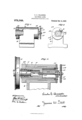
The present invention provides for the lateral insertion and removal of the axle without the need for retracting the tailstock spindles endwise, and the invention will be readily understood from the following description taken in connection with the accompanying drawing in which Figure l is a side elevation of a tailstock embodying an exemplification of the invention: Fig. 2 an elevation of the inner end of the tailstock: and Fig. 3 a vertical longitudinal section of the same.
In the drawing :1, indicates the car axle: 2, one of its end journals: 8, one of the car wheels on the axle: 4:, a segmental bushing engaging the axle-journal and having a tapered exterior engaging toward the car wheel: 5, a flexible spring ring which may, if desired, be employed in holding the segments of the bushing together while permitting their ready application to and removal from the journal when the journal is free of the tailstock: 6, the body of the tailstock: 7, the tailstock bearing: 8, a gap in one of the walls of the tailstock bearing at its inner end, the gap being of sufficient size to permit the free passage through it of the axle-journal with its attached segmental bushing: 9, the tailstock spindle mounted to turn in the tailstock bearing: 10, an inner collar on the tailstock spindle: 11, an outer collar on the tailstock spindle, this latter collar being preferably detach- Specification of Letters Patent.
Application filed May 9, 1910.
Patented Oct. 11, 1910.
Serial No. 560,140.
ably bolted to the outer end of the tailstock spindle: 12, a gap in one side of the inner end of the tailstock spindle, this gap being of such size as to permit the entry and exit of the axle journal and its bushing, laterally, when the gap in the spindle is brought into coincidence with the gap in the tailstock bearing: 13, a hollow chuck plunger fitted concentrically within the spindle and splined therein and capable of sliding endwise in the spindle: 14:, a tapering bore at the front end of the chuck-plunger, this bore fitting the exterior of the segmental bushing: 15, a screw journaled in the outer end of the tailstock spindle and engaging the chuck-plunger and serving as means by which the chuck-plunger may be adjusted endwise: 16, a hand-wheel on this screw: 17 the inner hub of the hand-wheel: 18, an annular teeshaped slot formed at the outer end of the tailstock spindle, concentrically around screw 15: and 19, a bolt engaging this tee-slot and the hub of the hand-wheel and serving to lock screw 15 in adjusted position.
When work is to be inserted in the lathe, each journal of the axle is to have its segmental bushing placed upon it and the chuck-plungers are to be retracted. The work may now be placed in the lathe, the axle-journals passing through the gaps in the tailstock bearings and their spindles. The hand-wheels are now to be manipulated so as to move the chuck-plungers inwardly toward the car wheels, these plungers engaging the segmental bushings and clamping them closely to the axle journals, after which bolt 19 is to be tightened to prevent the parts working loose. As the wheel and axle-structure is rotated, in the usual operation of the lathe, the tailstock spindles turn in the tailstock bearings, the tailstock spindles forming what might be called artificial journals for the axle.
I claim 1. A car wheel lathe of the class referred to comprising, a tailstock bearing having a gap through the inner end of one of its walls, a hollow spindle journaled therein and having a gap through the inner end of its wall, a chuck-plunger fitted to slide axially within the spindle and having at its forward end a flaring bore, a segmental bushing fitting said bore and adapted to engage an axle-journal, and means for adjusting said chuck-plunger endwise in the spindle, combined substantially as set forth.
2. A car wheel lathe of the class referred to comprising, a tailstock bearing having a gap through the inner end of one of its walls, a hollow spindle journaled therein and having a gap through the inner end of its wall, a chuck-plunger fitted to slide axially within the spindle and having at its forward end a flaring bore, a segmental bushing fitting said bore and adapted to engage an axle-journal, a screw axially journaled in the outer end of the spindle and adapted to turn with the spindle and to be turned independently thereof and threaded into the chuck-plunger, and means for turning' said screw, combined substantially as set forth.
3. A car wheel lathe of the class referred to comprising, a tailstock bearing having a gap through the inner end of one of its walls, a hollow spindle journaled therein and having'a gap through the inner end of its wall, a chuck-plunger fitted to slide axially within the spindle and having at its forward end a flaring bore, a segmental bushing fitting said bore and adapted to engage an axle-journal, a screw axially journaled in the outer end of the spindle and adapted to turn with the spindle and to be turned independently thereof and threaded into the chuck-plunger, means for turnin said screw, and a locking device to lock said screw in adjusted position relative to the spindle, combined substantially as set forth.
4. A car wheel lathe of the class referred to comprising, a tailstock bearing having a gap through the inner end of one of its walls, a hollow spindle journaled therein and having a gap through the inner end of its wall, a chuck-plunger fitted to slide axially within the spindle and having at its forward end a flaring bore, a segmental bushing fitting said bore and adapted to engage an axle-journal, a screw axially journaled in the outer end of the spindle and adapted to turn with the spindle and to be turned independently thereof and threaded into the chuck-plunger, a hand-wheel on the outer end of the screw, and a bolt engaging the inner hub of the hand-wheel and a concentric tee-slot in the outer end of the spindle and serving to lock the screw in adjusted position, combined substantially as set forth.
CHARLES Gr. DRAE SEKE.
Witnesses HENRY BERTRAM, FRANK CRONIN.
Priority Applications (1)
| Application Number | Priority Date | Filing Date | Title |
|---|---|---|---|
| US56014010A US972348A (en) | 1910-05-09 | 1910-05-09 | Car-wheel lathe. |
Applications Claiming Priority (1)
| Application Number | Priority Date | Filing Date | Title |
|---|---|---|---|
| US56014010A US972348A (en) | 1910-05-09 | 1910-05-09 | Car-wheel lathe. |
Publications (1)
| Publication Number | Publication Date |
|---|---|
| US972348A true US972348A (en) | 1910-10-11 |
Family
ID=3040729
Family Applications (1)
| Application Number | Title | Priority Date | Filing Date |
|---|---|---|---|
| US56014010A Expired - Lifetime US972348A (en) | 1910-05-09 | 1910-05-09 | Car-wheel lathe. |
Country Status (1)
| Country | Link |
|---|---|
| US (1) | US972348A (en) |
-
1910
- 1910-05-09 US US56014010A patent/US972348A/en not_active Expired - Lifetime
Similar Documents
| Publication | Publication Date | Title |
|---|---|---|
| US2526487A (en) | Lathe | |
| US952084A (en) | Car-wheel lathe. | |
| US987227A (en) | Car-wheel lathe. | |
| US1017968A (en) | Centering-chuck. | |
| US1010616A (en) | Car-wheel lathe. | |
| US334832A (en) | Car-wheel lathe | |
| US1715835A (en) | Mechanism for truing and dressing grinding wheels | |
| US340207A (en) | Alexander gordon | |
| US1748343A (en) | Grinding apparatus | |
| US993901A (en) | Cylinder-grinding machine. | |
| US1908592A (en) | Work-rotating structure for machine tools | |
| US2153971A (en) | Chucking means | |
| US1515683A (en) | Spindle bearing for metal-working machines | |
| US1328195A (en) | Journal-bushing | |
| US1757953A (en) | Truck | |
| US288718A (en) | mcintyre | |
| US330628A (en) | Car-wheel lathe | |
| US355829A (en) | lindstrom | |
| US716496A (en) | Spindle-bearing for axles. | |
| US1922404A (en) | Tailstock for lathes, grinders, and the like | |
| US353302A (en) | Turning-lathe | |
| US349908A (en) | Lathe for turning journals of car-axles | |
| US1733892A (en) | Clamping means for wheel lathes | |
| US565155A (en) | Electric motor | |
| US894863A (en) | Collapsible taper-thread tap and reamer. |